

Page 1
TP315-102 HDMI OVER ANYWIRE RECEIVER User’s Guide
Welcome!
Everyone at Altinex greatly appreciates your purchase of the
TP315-102. We are confident that you will find it to be reliable and
simple to use. If you need support, please do not hesitate to call
us at 714-990-2300.
At Altinex, we are committed to developing unique and state of
the art Signal Management Solutions® for demanding audiovisual
installations. Welcome to the Altinex family of satisfied customers
around the world!
1. Precautions and Safety Warnings
Please read this manual entirely before using your
TP315-102. You can download a full version of this
manual at www.altinex.com. These instructions are to
ensure the reliable operation of your switcher and to
prevent fire and shock hazards. Please read them
carefully and heed all warnings.
1.1 General
Qualified Altinex service personnel or their authorized
representatives must perform all service.
1.2 Installation Precautions
To prevent fire or shock, do not expose this unit to water
or moisture. Do not place the TP315-102 in direct sunlight,
near heaters or heat-radiating appliances, or near any
liquid. Exposure to direct sunlight, smoke, or steam can
harm internal components.
Handle the TP315-102 carefully. Dropping or jarring can
cause damage.
Do not pull any cables attached to the TP315-102.
1.3 Cleaning
Clean the TP315-102 with a dry cloth only. Never use
strong detergents or solvents such as alcohol or thinner.
1.4 FCC Notice
This device complies with Part 15 of the FCC Rules.
Operation is subject to the following two conditions: (1)
This device may not cause harmful interference, and (2)
this device must accept any interference received,
including interference that may cause undesired operation.
This equipment has been tested and found to comply with
the limits for a Class B digital device, pursuant to Part 2 of
the FCC Rules. These limits are designed to provide
reasonable protection against harmful interference when
the equipment is operated in a commercial environment.
This equipment generates, uses, and can radiate radio
frequency energy and, if not installed and used in
accordance with the instructions found herein, may cause
harmful interference to radio communications. Operation
of this equipment in a residential area is likely to cause
harmful interference in which case the user will be
required to correct the interference at their own expense.
Any changes or modifications to the unit not expressly
approved by Altinex, Inc. could void the user’s authority to
operate the equipment.
2. Installation Procedures
Note: Download and read the entire online manual to become familiar with the
TP315-102 and for detailed installation instructions, including multiple receiver
wiring.
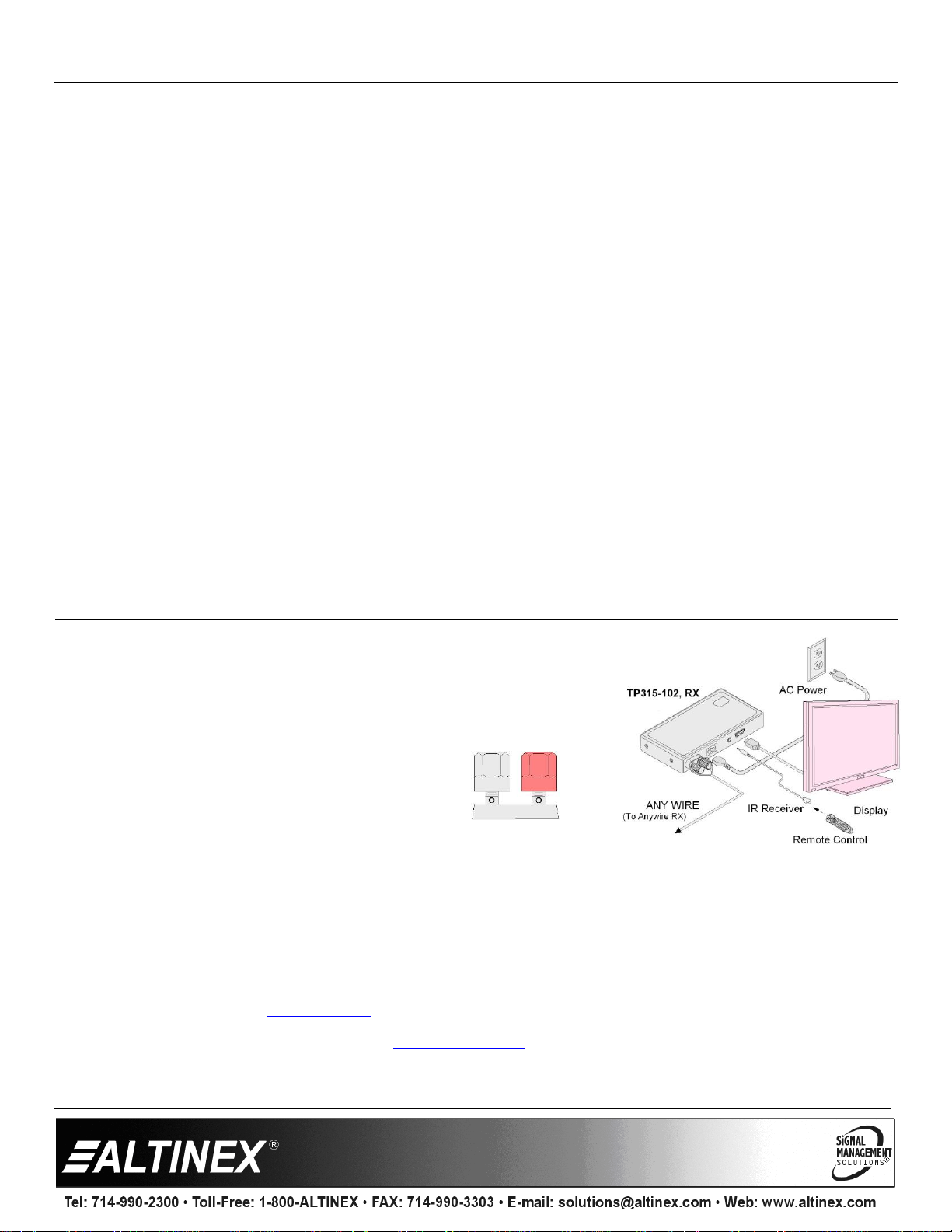
Step 1: Connect the TP315-102 Receiver to the TP315-101 Transmitter using any
2 wires or 2-conductor cable. For best results, use 24 to 12 gage wire; the 12
gage limitation is due to the opening in the terminal
connector.
The terminals are red and black, but there is no
polarity. Connect either wire to either terminal.
Step 2: Connect the TP315-102 to AC power using the cord provided.
Step 3: Connect the display to the HDMI output on the TP315-102 using the HDMI cable provided.
Step 4. The Anywire receiver is now operating. Once the transmitter detects the receiver, video is displayed automatically.
Step 5. The Anywire Transmitter/Receiver pair allows IR pass-through from the receiver (far side) to the transmitter (near side). An IR
receiver is included with the TP315-102 and may be connected to the HDMI display (or anywhere accessible to the user)
allowing a remote control on the user/receiver side to control the source on the transmitter side of the Anywire installation. The
Anywire transmitter includes an IR emitter.
3. Warranty and Return Policies
Please visit the Altinex website at www.altinex.com for details on warranty and return policies. In the case of a unit needing repair,
please complete a RMA (return material authorization) form by clicking the Warranty link located on the bottom of the Altinex
homepage. Once completed, please email the form to [email protected].
400-0648-002
Page 2
TP315-102 User’s Guide
Features/Description
TP315-102
Input Connectors
Anywire Video
Terminal Post F (2)
IR Receiver
3.5 mm Audio F (1)
AC Power
C7 M (1)
Output Connectors
Digital Video + Audio
HDMI F, Type A (1)
Compatibility
Signal types
HDMI
Signal resolution
720p, 1080i, and 1080p
Accessories Included
HDMI Cable
n/a
AC Power Cord,
NEMA 1-15P to IEC C7
n/a
IR Receiver
n/a
Mechanical
TP315-102
Material
Aluminum
Color
Black
Height
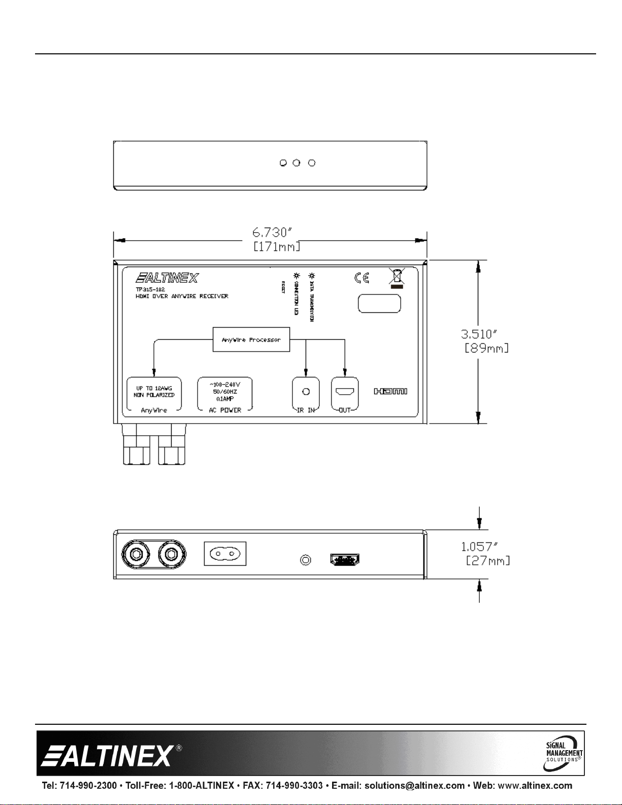
1.05 in (27 mm)
Width
6.73 in (171 mm)
Depth
3.51 in (89 mm)
Weight
1.0 lbs. (0.45 kg)
T° Operating
10°C-45°C
Humidity
90% non-condensing
MTBF (calc.)
38,000 hrs.
Electrical
TP315-102
Video Input Signals
Digital Video + Audio
Anywire
Video Output Signals
Digital Video + Audio
HDMI Standard
Power
100~240 VAC
7 W max.
100 VAC at 70 mA
240 VAC at 30 mA
4. Technical Specifications
Specifications are subject to change due to design improvements. Please see www.altinex.com for up to date information.
Table 2. TP315-102 Mechanical
Table 1. TP315-102 General
400-0648-002 2
Table 3. TP315-102 Electrical
Page 3
TP315-102 User’s Guide
5. About Your TP315-102
HDMI over 2-conductor cable
Automatic input detection
HDMI resolutions 720p, 1080i, and 1080p
Transmission up to 300 m
IR pass-through control
The TP315-102 HDMI over Anywire receiver allows the receipt of 1080P HDMI signals up to 300 m using a simple 2-conductor cable.
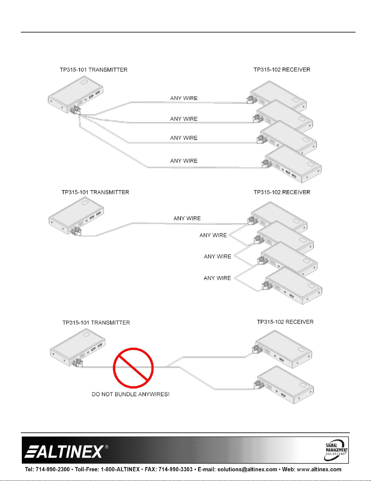
A single transmitter is capable of driving up to 4 receivers using either 4 individual wire pairs over 300 m each, or by daisy chaining the
receivers. The only restriction being the wire pair from the transmitter to each receiver cannot be bundled together as crosstalk will
occur.
The TP315-102 is an economical solution for many audiovisual installations. The 2 wire solution makes installation easy without the
need to cut and splice wires and install expensive connectors or purchase costly cables. Simply route your wires, cut and trim the
installation and connect to the terminals. That's it!
The unique design of the Anywire Receiver provides stable video over greater distances than other designs. IR pass-through for
receiver side to transmitter side control is provided without corrupting the HDMI signal during transmission of IR signals.
Operation does not require any user control or interaction. Simply connect the Anywire input and when the transmitter detects the
receiver the receiver begins video transmission to the display.
400-0648-002 3
Page 4
TP315-102 User’s Guide
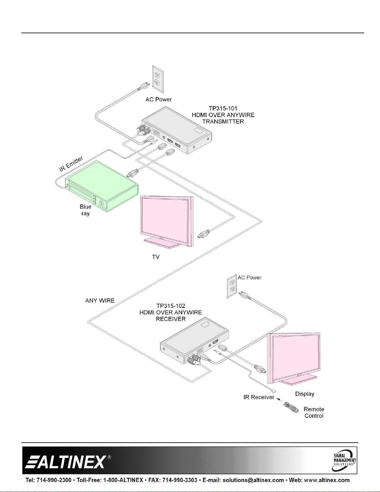
6. Application Diagrams
Diagram 1: Typical Setup
400-0648-002 4
Page 5
TP315-102 User’s Guide
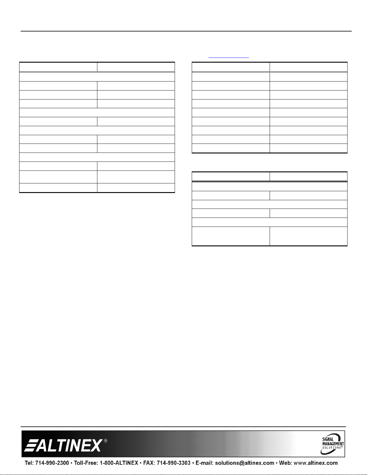
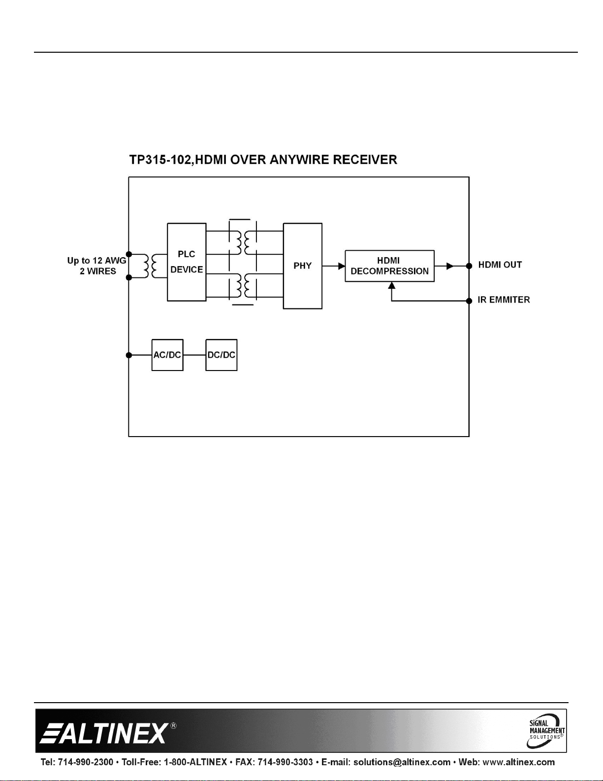
Diagram 2: Internal View
400-0648-002 5
Page 6
TP315-102 User’s Guide
Diagram 3: Dimensions
400-0648-002 6
Page 7
TP315-102 User’s Guide
Diagram 4: Multiple Receiver Setup
400-0648-002 7
Page 8

TP315-102 User’s Guide
Anywire
Symptom
Resolution
LEDs on Are Off
The unit may not be receiving power.
1. Make sure the unit is plugged into a working AC outlet. Use only the power cord provided.
2. The Connected LED should be on and green.
Data Transmission
LED is flashing very
slow
The transmitter and receiver are not communicating.
1. Check the 2 wire connection; make sure both wires are connected.
2. Make sure the transmitter is powered on.
3. Press the reset button on the side of the unit or reset power to force the transmitter to try and
re-establish a connection.
No Display
The HDMI input signal may be missing.
1. Check the source and make sure there is a signal present.
2. Make sure the source resolution is 720p, 1080i, or 1080p.
3. Make sure both the TP315-101 and TP315-102 are powered and the Connected LEDs are both
green.
4. Make sure the monitor has power and is turned on.
5. Verify the monitor is connected to the TP315-102 Receiver's HDMI output
6. Make sure the monitor's correct HDMI input number is selected.
Poor Output Image
1. The source resolution may not be compatible with the projector or other display device. Try
other resolutions from the source.
2. The source and display may not be compatible. Connect the source directly to the input of the
projector or other display device. If the image is poor the devices may be incompatible.
3. If using multiple receivers, make sure that the transmission lines are not bundled together at any
point in the transmission. If the cables are bundled (zip tied together) this causes crosstalk
between the different channels and can result in image problems.
7. Operation
The TP315-102 requires no adjustments for performance.
Once set-up, the TP315-102 Anywire Transmitter will work
trouble-free without user intervention.
7.1 Reset Button
A reset button is provided on the side of the unit to allow a
forced reset without having to disconnect power. Use this only
if there are problems connecting to the receiver; typically after
a new display is installed or after a power outage.
8. Troubleshooting Guide
We have carefully tested and have found no problems in the supplied TP315-102. However, we would like to offer suggestions for the
following:
400-0648-002 8
 Loading...