

Page 1
SWITCHERS
MANUAL PART NUMBER: 400-0150-001
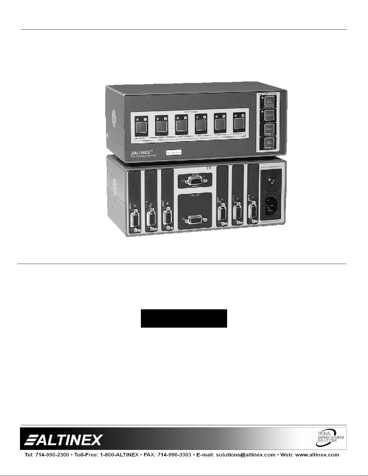
MX2406RM
6 - IN, 1 - OUT
VGA SWITCHER
USER’S GUIDE
Page 2

TABLE OF CONTENTS
Page
PRECAUTIONS / SAFETY WARNINGS ................2
GENERAL...........................................................2
RACK MOUNT SAFETY GUIDELINES...............2
INSTALLATION...................................................2
CLEANING..........................................................2
FCC / CE NOTICE...............................................2
ABOUT YOUR SWITCHER....................................3
TECHNICAL SPECIFICATION...............................3
SWITCHERS
DESCRIPTION OF
SELECT INPUT...................................................5
AUTO SWITCH MODE BUTTON........................5
STAND BY / ALL CHANNELS OFF BUTTON.....5
RESET BUTTON.................................................5
BEEP ON/OFF BUTTON.....................................5
POWER UP DEFAULT SET................................5
ANALOG OUTPUT..............................................6
POWER SUPPLY................................................6
BI-DIRECTIONAL SWITCHING ..........................6
APPLICATION DIAGRAM ......................................6
INSTALLING YOUR SWITCHER ...........................7
OPERATION ..........................................................7
RS-232 CONTROL..............................................7
RS-232 PROTOCOL...........................................8
MASTER-SLAVE CONFIGURATION..................9
CONTACT CLOSURE (O NE WIRE ANALOG)
CONTROL...........................................................9
MANUAL LOOP CONTROL..............................10
LOOP CONTROL WITH RS-232 COMMAND...10
ACCESSORIES....................................................11
FREQUENTLY ASKED QUESTIONS...................11
TROUBLESHOOTING GUIDE .............................12
ALTINEX POLICY.................................................13
LIMITED WARRANTY.......................................13
RETURN POLICY .............................................13
CONTACT INFORMATION...............................13
MX2406RM
..............................4
1
Page 3
SWITCHERS
PRECAUTIONS / SAFETY WARNINGS 1
Please read this manual carefully before using your
MX4206RM
future reference. These safety instructions are to
ensure the long life of your
prevent fire and shock hazard. Please read them
carefully and heed all warnings.
1.1 GENERAL
Unauthorized personnel shall not open the unit
•
since there are high-voltage components inside.
Qualified ALTINEX service personnel, or their
•
authorized representatives must perform all
service.
1.2 SAFETY GUIDELINES FOR THE RACK-
MOUNTING OF THE MX2416RM
Maximum operating ambient temperature is 35
•
(degrees C).
Never restrict the airflow through the device’s
•
fan or vents.
When installing equipment into a r ack, distr ibute
•
the units evenly. Otherwise, hazardous
conditions may be created by an uneven weight
distribution.
Connect the unit to a properly rated supply
•
circuit.
Reliable Earthing (Grounding) of Rack-Mounted
•
Equipment should be maintained.
1.3 INSTALLATION
For best results, place the
•
on a flat, level surface in a dry area away f rom
dust and moisture.
To prevent fire or shock, do not expose this unit
•
to rain or moisture. Do not place the
Switcher in direct sunlight, near heaters or heat
radiating appliances, or near any liquid.
Exposure to direct sunlight, smoke or steam can
harm internal components.
Handle the
•
Dropping or jarring can damage internal
components.
Do not place heavy objects on top of the
•
MX2406RM
wall, use only an ALTINEX made mounting
Switcher. Keep this manual handy for
and to
Switcher
MX2406RM
MX2406RM
. If the
MX2406RM
MX2406RM
Switcher carefully.
MX2406RM
is to a table or
accessories like rack mount shelf
rack mount ears
optimum setup.
To turn off the main power, be sure to remove
•
the cord from the power outlet. The power outlet
socket should be installed as near to the
equipment as possible, and should be easily
accessible.
Do not pull the power cord or any cable that is
•
attached to the
If the
•
1.4 CLEANING
Unplug the
•
1.5 FCC / CE NOTICE
This device complies with Part 15 of the FCC
•
This equipment has been tested and found to
•
•
MX2406RM
an extended period of time, disconnect the
power cord from the power outlet.
cleaning. Clean surfaces with a dry cloth. Never
use strong detergents or solvents such as
alcohol or thinner. Do not use a wet cloth or
water to clean the unit.
Rules. Operation is subject to the f ollowing two
conditions: (1) This device may not cause
harmful interference, and (2) this device must
accept any interference received, including that
may cause undesired operation.
comply with the limits for a Class A digital
device, pursuant part 15 of the FCC Rules.
These limits are designed to provide reasonable
protection against harmful inter ference when the
equipment is operated in a commercial
environment. This equipment generates, uses,
and can radiate radio frequency energy and, if
not installed and used in accordance with the
instruction manual, may cause harmful
interference to radio comm unications. Operation
of this equipment in a resident ial area is likely to
cause harmful interference in which case the
user will be required to correct the interference
at his own expense.
Any changes or modifications to the unit not
expressly approved by ALTINEX, Inc. could void
the user’s authority to operate the eq uipm ent .
DA1299RM
MX2406RM
Switcher is not to be used for
MX2406RM
Switcher.
power cord before
DA1298RM
and cables for
or
2
Page 4
SWITCHERS
ABOUT YOUR SWITCHER 2
The
MX2406RM
designed to allow the non-simultaneous connection
of up to six computer video sources to a single
monitor or projector. The
controllable using its built-in front panel, through
RS-232, or through contact closures. Contact
closure control requires the use of an optional
adapter, part #
The
MX2406RM
therefore may be used to switch other signal t ypes
as well, including RGBHV, RGBS, RGsB,
Component Video (Y, R-Y, B-Y), S-Video (Y/C),
Composite Video, Audio, and even RS-232,
assuming the appropriate adapter cable is used.
Since the
MX2406RM
also be used bi-directionally – a signal can be
routed “backwards” through the switcher t o allow a
single source to be connected to as many as six
displays.
The
MX2406RM
provides a means of interconnection for RS-232
and contact closure control as well as other special
features. For instance, when multiple
units are looped together to create a larger
switcher, two pins on the 9-pin control ports can be
connected to make the switcher respond as a
single unit. Using a similar method, multiple
MX2406RM
Master-Slave mode, with all units responding to a
single button selection.
Using optional hardware, a single
be rack-mounted by itself or t wo units can be ra ckmounted side-by-side.
is a 6-in 1-out relay switcher
is
RC5204CC
MX2406RM
.
uses relays internally and
uses relays internally, it can
offers a 9-pin control port, which
MX2406RM
units can be made to operate in a
MX2406RM
can
TECHNICAL SPECIFICATIONS 3
FEATURES/
DESCRIPTION
GENERAL
Inputs
VGA Input Connector Six 15-pin HD Female
Outputs
VGA Output Connectors 15-pin HD Female
Compatibility
VGA/SVGA/XGA/UXGA/,
MX2406RM
6
1
RGBHV, RGBS, RGsB,
Component Video (Y, R-Y,
B-Y), S-Video (Y/C),
Composite Video,
Table 1.
MECHANICAL MX2406RM
Material 0.1” Al
Finish Gray
Top Panel Lexan
Height (inches) 3.38in (86mm)
Width (inches) 8.50in (216mm)
Depth (inches) 4.38in (111mm)
Weight (pounds) 3.0lbs (1.36kg)
Ship Weight (pounds) 4.0lbs (1.82kg)
T° Operating 10°C-35°C
T° Maximum 50°C
Humidity
MTBF (calculations) 40,000 hrs
Table 2.
ELECTRICAL MX2406RM
Input Video Signal
Analog Signal +/-10V p-p max
Impedance 75 Ohms
Input Sync Signal
Composite Sync TTL(+/-),Analog 0.3-1.0V
Sync on Green -0.3V
Impedance pass-through
Output Video Signals
Analog Signal +/-10V p-p max
Fall/Rise Time (ns) 1.9
Impedance 75 Ohms (pass-through)
Output Sync Signal
Composite Sync
Sync on Green -0.3V
Impedance pass-through
Frequency Compatibility
Typical Video Bandwidth 400 MHz @ -3 dB
Horizontal 15-200 kHz
Vertical 30-190 Hz
Cross-talk -48dB @ 10 MHz
Coupling DC
Power
External Power Adapter 90-140V/200-240V
Power Consumption 12 watts max.
Table 3.
MX2406RM
MX2406RM
MX2406RM
General
90% non-condensing
Mechanical
TTL(+/-), Analog 0.3-1.0V
(not buffered)
Electrical
3
Page 5
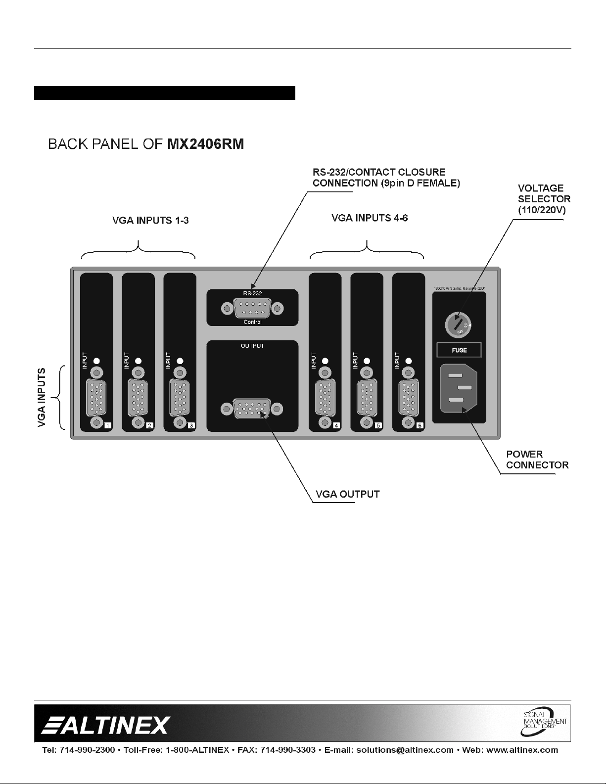
DESCRIPTION OF MX2406RM 4
SWITCHERS
4
Page 6
SWITCHERS
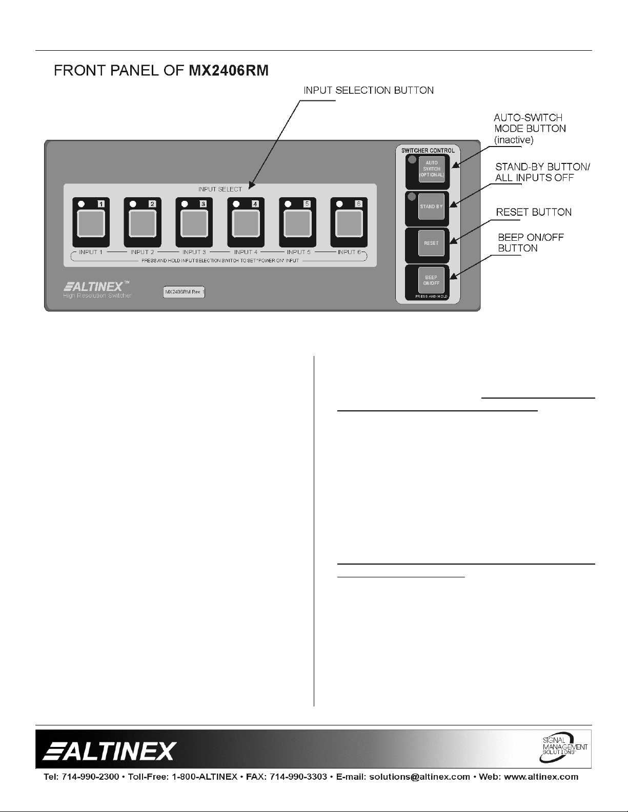
The front panel of t he
to essentially all of the switcher’s capabilities. In
addition to standard switching functions, the unit has
control and switching functions that could be very
useful in a variety of special applications.
4.1 SELECT INPUT
When buttons 1 through 6 are pressed, the
corresponding INPUT will be selected and
displayed. LED’s on the front and rear panel will
light simultaneously to indicate which selection has
been made.
4.2 AUTO SWITCH MODE BUTTON
This function is non-operational at t his time and is
reserved for future upg r ades.
4.3 STAND BY / ALL CHANNELS OFF BUTTON
This function allows a user to turn OFF all input
signals. It is very useful when the
Switcher is used in applications where there is a
need to turn the display or the source OFF. Press
this function key (F2) to switch to a no signal
condition. The LED next to the F2 funct ion key will
light to indicate that the switcher is in t his m ode. T o
resume input select switching, simply press the
desired INPUT.
MX2406RM
provides access
MX2406RM
4.4 RESET BUTTON
This function allows a user to RESET the switcher
without unplugging the unit. Press the f unction key
RESET (F3) and hold it for 2 seconds. W hen you
hear a beeping sound, release the key. All of the
LED’s will flash simultaneously. The switcher is
now reset. All previous defaults, such as power on
channel default and other user settings are
maintained.
4.5 BEEP ON/OFF BUTTON
This function allows a user to have audible
feedback when buttons are pressed. The factory
default is beep ON; however, in some applications,
sound may be undesirable. To disable sound,
press this function key (F4) and hold it for
approximately 2 seconds until a beeping sound is
heard. The function is now disabled. To enable it,
repeat the same steps. The setting is stored in the
memory and is maintained during power up
sequence.
4.6 POWER UP DEFAULT SET
This function allows a user to select the channel
that will be ON at power up. To select the default
channel press the selected channel switch and
hold it for approximately 2 seconds until you hear a
5
Page 7
SWITCHERS
beeping sound. If the unit is t urned off and turned
back on, the LED of the selected channel should
light.
4.7 ANALOG OUTPUT
The analog output of the
for controlling several switchers simultaneously.
The analog amplifier drives analog output pin 9 on
a 9-pin “D” connector. The output can swing from 0
V to approximately 5.0 V. The output impedance of
this pin is 100 Ohms and it can sink or source up to
5 mA of current. By using this output, several
switchers can operate in gang mode. To do this,
the analog output of the master switcher (pin 9) is
connected to the analog input of the slave
switchers (pin 9). Now, every time a channel is
selected on the master switcher, the output voltage
of the analog output will be set to switch all other
switchers into the same channel. The simplicity of
this approach is that only 2 wires (one to pin 9 and
one to ground) are required t o connect and control
all of the switchers. The selection of channels can
also be accomplished by RS-232 on the master
switcher with all slave switchers connected through
the analog control pin. A maximum of 4 switchers
can be connected in this configuration.
MX2406RM
can be used
4.8 POWER SUPPLY
The
MX2406RM
available on pin 8 of the 9-pin “D” connector. This
voltage can be used to drive external circuits or as
a pull up voltage for open collector type outputs.
The total current on this pin should not exceed
150 mA of continuous operation or 500 mA for 5
minutes.
4.9 BI-DIRECTIONAL SWITCHING
The
bandwidth relays to provide you with a 400 MHz
bandwidth. Each input, when not selected, is
terminated to a 75-Ohms resistor. This is done to
make sure that video lines are always terminated
whether a channel is selected or not.
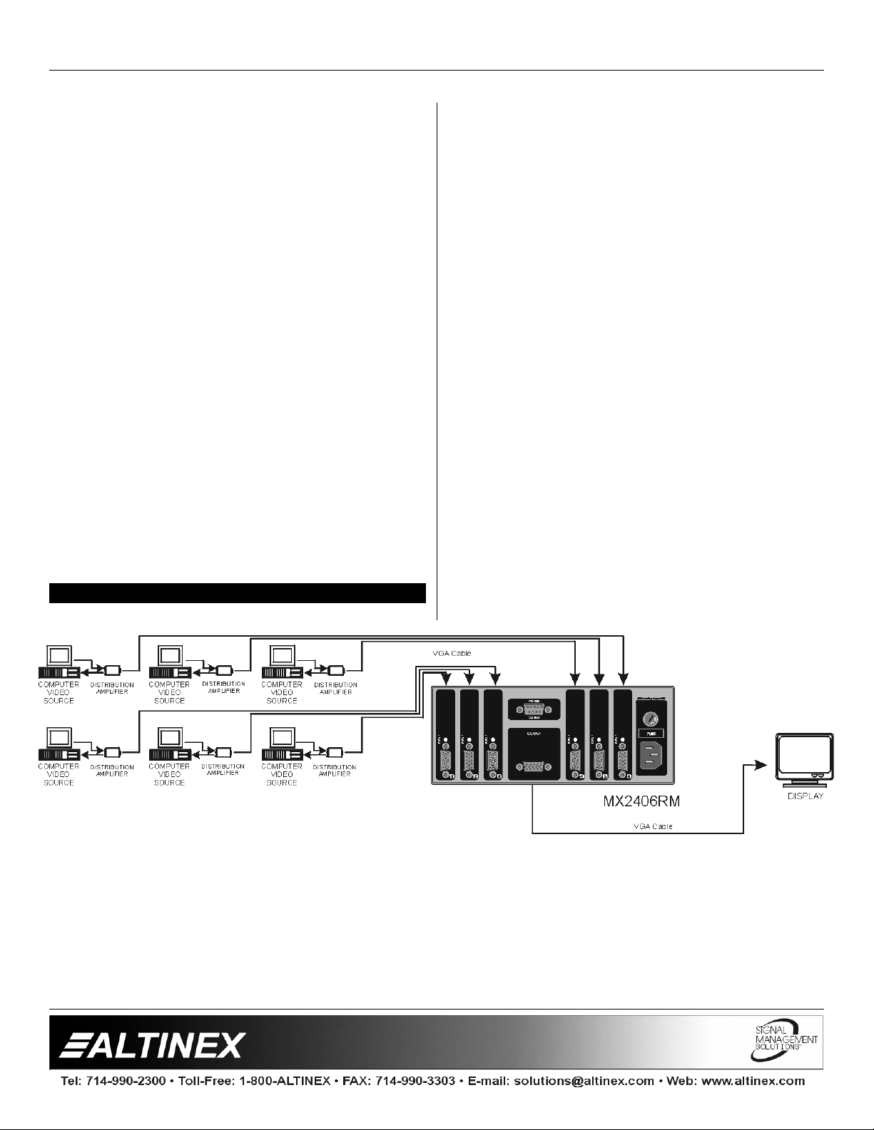
In addition to forward connection, the
can be hooked up in a reverse direction. In this
configuration one video source is selectively sent to
each of the video monitors. This capability is
referred to as bi-directional switching. In this
configuration only one display device can be
operational at any given time.
MX2406RM
Switcher has 5 V power supply
Switchers use very high
MX2406RM
APPLICATION DIAGRAM 5
6
Page 8
SWITCHERS
INSTALLING YOUR SWITCHER 6
Step 1
Step 2.
Step 3.
Step 4.
Step 5.
Contact Closure control requires the use of part #
RC5204CC
CONGRATULATIONS! YOU ARE DONE.
. Make sure that the power input is set to
the proper AC voltage in your countr y. An
incorrect setting can result in unit damage
not covered by warranty.
Connect the power cord to the unit and
plug it into the power outlet.
Connect the cables from the video sources
(computers) to the input channels and
connect the output channel to the display
device (i.e. monitor or projector)
If a control system is used to control the
unit connect RS-232 port to the control
system’s RS-232 card. An improper hook
up may result in RS-232 interface damage.
Verify that the picture quality on the display
is good. If you are not receiving a signal,
make sure that the display is compatible
with the resolution of the computer
graphics card.
Cable.
If you experience any problems, please
call 1-800-258-4623 or 1-714-990-2300 for
international calls.
OPERATION 7
7.1 RS-232 CONTROL
The
MX2406RM
connector on its rear panel that allows access to a
variety of control capabilities.
9-pin D connector
It is generally recommended to select a single
method of control for each application, as the
activation of several different controls
simultaneously may cause unpredictable results.
The majority of control systems and computers
used in presentation system applications use the
RS-232 communications standard.
To connect the
system or computer for RS-232 Control, only three
pins are required on each port: Transmit (TX),
Receive (RX), and Ground (GND). The Transmit
pin from the control system or computer must be
connected to the Receive pin of the switcher
control port; do not connect Transmit to Transmit
or Receive to Receive.
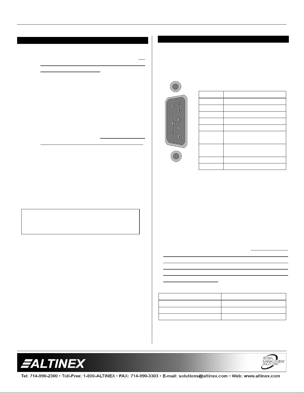
Switcher uses a female 9-pin HD
PIN No. PIN Designation
1 No connection
2 RS-232 Transmit
3 RS-232 Receive
4 No connection
5 Ground
6 Multiple Switcher Loop
Control
7 Analog Switch Voltage
Input
8 +5 V (150 mA max)
9 Analog Voltage Output
MX2406RM
Switcher to a control
The following are typical cable wiring pin outs:
IBM PIN No.
32
23
75
Connection IBM-PC 25-pin D to
Note: 5, 6, 20 shorted together in IBM side only.
7
MX2406RM
MX2406RM
PIN No.
9-pin D
Page 9
SWITCHERS
IBM PIN No.
22
33
55
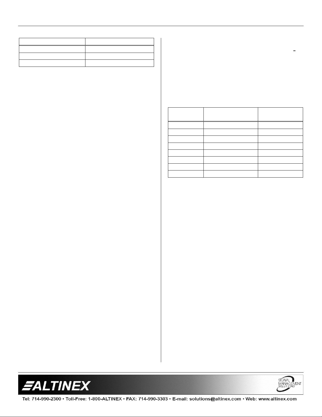
Connection IBM-PC 9-pin D to
Note: 4, 6, 8 shorted together in IBM side only.
Port setting preferences for the control system or
computer being used to control the switcher should
be set as follows:
BAUD RATE (Bits per second) 2400
Data bits 8
Parity None
Stop Bits 1
There is no software or hardware flow control
implemented. The RS-232 input has a 6-char acter
buffer and will not execute additional commands
until the previous command is fully processed.
7.2 RS-232 PROTOCOL
[INP0] All channels O FF
[INP1] Select Input 1
[INP2] Select Input 2
[INP3] Select Input 3
[INP4] Select Input 4
[INP5] Select Input 5
[INP6] Select Input 6
[RSET] Reset unit to user defaults
[VERN] Returns firmware version
numbers
Commands must be issued as shown, in ALL
CAPS and with the brackets [ ] included in the
command string. After processing a valid
command, an [OK] string will be returned. A
command echo will also follow the [OK].
MX2406RM
MX2406RM
PIN No.
9-pin D
If the control system being used is not setup to wait
for the [OK] str ing, it is important to include a 100
milliseconds delay between each command.
The
MX2406RM
feedback commands from the switcher to the
control system when the buttons on the front panel
of the switcher are pressed.
The feedback codes are as f ollows:
Key
pressed
1 Input Select [INP1]
2 Input Select [INP2]
3 Input Select [INP3]
4 Input Select [INP4]
5 Input Select [INP5]
6 Input Select [INP6]
STAND BY All Outputs OFF [INP0]
RESET Reset [RSET][INPx]
The following commands are added to the
standard set of commands in order to facilitate
control of multiple units using a single RS-232
control port. These commands ar e available on the
switcher that has firmware revision number: 2.0.
Use [VERN] commands to determine the f irmware
revision. These commands add additional flexibility
to the switcher.
[InnOmm]
- Input Number 00 to 99
nn
- Output Number 01-99
mm
This command connects any input to any output.
The switching occurs as soon as the command is
completed. The input 00 is used to disconnect a
particular output from any input. For example,
command [I00O01] will disconnect output 1 from
any input.
Switcher is also designed to send
Description
Feedback
Code
For instance, a command of [INP1] would return
[OK][INP1]. The [VERN] command will return the
corresponding software version being used by the
switcher, such as an error string, [ERR] will be
returned.
8
Page 10
[OUTmm]
This command sets the switcher to respond to
specific output only. The default setting is output 1.
[SETxnnmm]
- select input number
x
- Minimum input number
nn
- Maximum input number
mm
SWITCHERS
This command is designed to allow the
to program each input to respond to a selected
range of input commands.
For example, if command [SET10104] is issued,
then the following commands will select only Input
1: [I01O01], [I02O01], [I03O01], and [I04O01]. In
other words a range of I/O commands can address
the same input. The default settings f or each of the
inputs are as follows Input 10101, Input 20202,
Input 30303, Input 40404, Input 50505, and Input
60606.
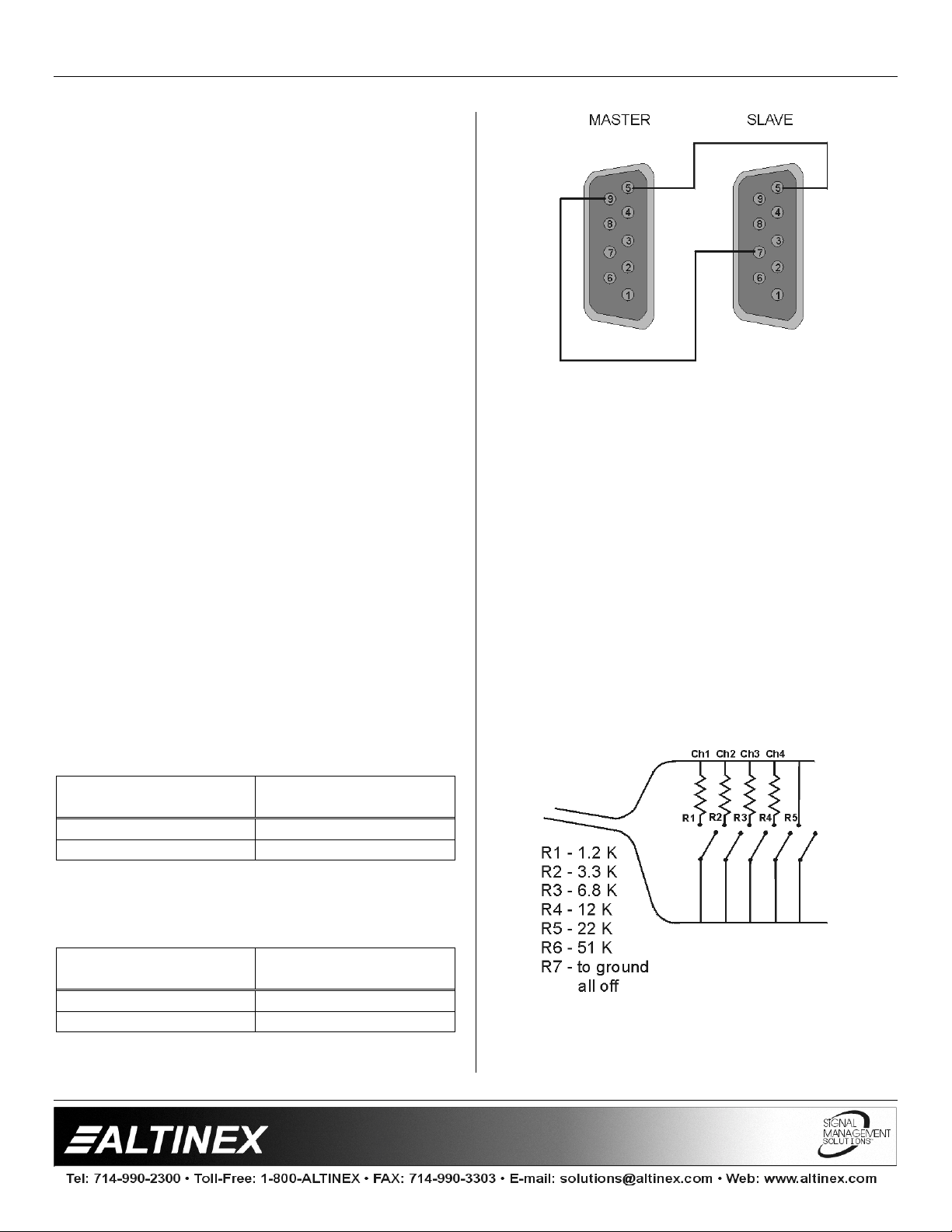
7.3 MASTER-SLAVE CONFIGURATION
These feedback codes allow multiple
Switchers to be connected in a Master-Slave
configuration, if desired.
When the cont rol ports of two units are connected
as shown below, the slave unit duplicates the
actions of the master unit. The same unit can st ill
be controlled from its front panel or through
another RS-232 control.
MX2406RM
Master PIN No.
Master-Slave Control Port Connection
9-pin D
23
55
MX2406RM
Slave PIN No.
MX2406RM
MX2406RM
9-pin D
With this conf iguration the Master unit has ultimate
control over slave unit.
7.4 CONTACT CLOSURE (ONE WIRE ANALOG)
CONTROL
The one wire control is an alternative to a multiwire contact closure control. This control pin allows
you to select different channels based on the DC
voltage level on the pin 7 of the 9 pin D connector.
Internally pin 7 is pooled up to 5 volts by 10k
resistor. Thus, by selecting proper resistor values
connected to ground any channel can be selected.
Although the channel selection by relay contact is
latching and will maintain the last relay-selected
channel, it is recommended that momentary
contact closures not be used. A typical resistor
values and wires connections are shown below.
A Master-Slave configuration can be achieved also
by Analog Switch Voltage using pin#9 and pin#7.
MX2406RM
Master PIN No.
Master-Slave Analog Switch Voltage Connection
9-pin D
97
55
MX2406RM
Slave PIN No.
9-pin D
In some cases it may be preferable to use a sevenconductor wire to control the switcher with contact
closures. The
9
RC5204CC
adapter is available to
Page 11
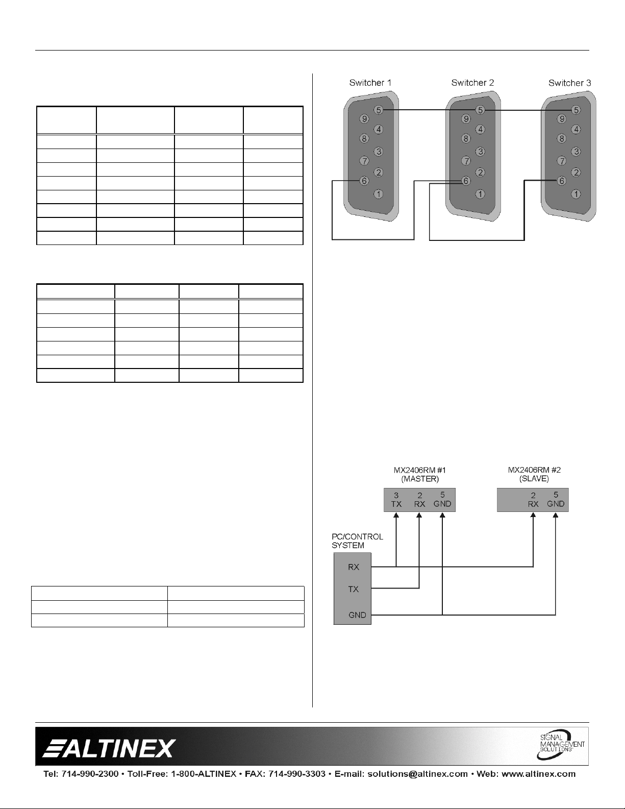
accommodate this need. The pin-outs for this
adapter are as follows:
SWITCHERS
9 pin “D”
Male
71.2K 1 1
73.3K 2 2
76.8K 3 3
7 12K 4 4
7 22K 5 5
7 51K 6 6
7 0 short 7 NONE
5 Ground 9
The following voltages apply for selecting the
required channel:
Input number min. (V) nom. (V) max. (V)
1 0.35 0.55 0.75
2 1.07 1.27 1.47
3 1.80 2.00 2.20
4 2.52 2.72 2.92
5 3.25 3.45 3.65
6 3.97 4.17 4.37
These voltage levels can be set using analog
outputs from different control systems or spare
dimmer control outputs.
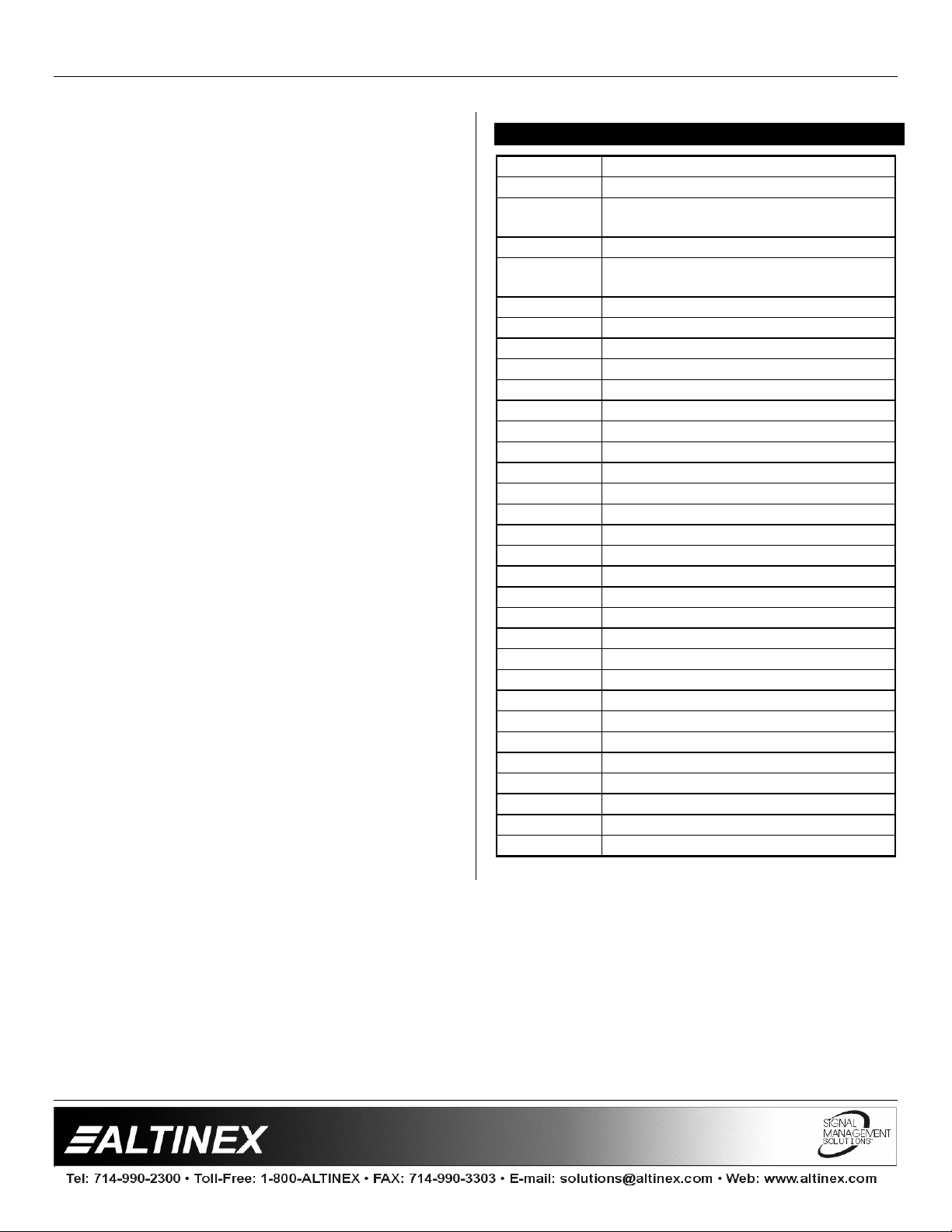
7.5 MANUAL LOOP CONTROL
Loop control is used when multiple units of the
MX2406RM
switcher. When the input channel button is pressed
the loop control pin is internally grounded and the
MX2406RM
default input.
Description 9 pin “D”
Female
are connected to form a single
Switcher selects INPUT 4 as the
Input
More specifically, the output of one switcher is
connected to INPUT 6 of the next switcher. Once
loop control is enabled these switchers will
automatically switch video signals to the output of
the second switcher through INPUT 6. Keep in
mind that you are always going to have one less
input than the total number of inputs available on
all switchers. The figure above is for an 11-in 1-out
switcher.
7.6 LOOP CONTROL WITH RS-232 COMMAND
When mult iple
form a single switcher and RS-232 commands are
used to control these units, please connect units
according to following diagram.
MX2406RM
units are connected to
In this configuration, loop control pin 6 on the 9 pin
D connector is connected to the same pin on all
switchers.
MX2406RM
MX2406RM
The loop control pin has an internal 100k r esist or to
+5volts. This limits the number of switchers that
can be looped to a maximum of 10 switchers that
can be daisy chained together using this method.
LOOP
66
55
9-pin “D” Loop
MX2406RM
LOOP
If you want to make 11 by 1 switcher using two 6
by 1 switchers, the following commands need to be
used to control these switchers:
Input 1 through Input 6 [OUT01]
10
Page 12
SWITCHERS
Input 7 through Input 11 [OUT02]
This will setup each switcher as a different output
number. To control the switchers use following
commands (connect the transmit line from the
control system to the receive line on both
switchers):
[I01O01] Select input number 1
[I02O01] Select input number 2
[I03O01] Select input number 3
[I04O01] Select input number 4
[I05O01] Select input number 5
[I06O01] Select input number 6
[I01O02] Select input number 7
[I02O02] Select input number 8
[I03O02] Select input number 9
[I04O02] Select input number 10
[I05O02] Select input number 11.
ACCESSORIES 8
Model No. Description
TABLE MOUNT HARDW ARE
TM1276
DA1298RM
DA1299RM
RC5204CC
RC5207CC
CB3703MR
CB3706MR
CB3715MR
CB3725MR
CB3750MR
CB3775MR
CB37100MR
CB37150MR
CB3903MR
CB3906MR
CB3915MR
CB3925MR
CB3950MR
CB3975MR
CB39100MR
CB39150MR
PC5301US
PC5302US
PC5303US
PC5304US
Table Mount bracket for 2U ½ RackWide
RACK MOUNTING ACCESSORIES
Rack mount shelf for two units side by
side
Rack ears for single unit.
CONTROL CABLES
Contact Closure Adapter 6 ft
Master-Slave Control cable
HIGH RESOLUTION VGA CABLE
3 feet VGA Male to Male
6 feet VGA Male to Male
15 feet VGA Male to Male
25 feet VGA Male to Male
50 feet VGA Male to Male
75 feet VGA Male to Male
100 feet VGA Male to Male
150 feet VGA Male to Male
HIGH RESOLUTION VGA CABLE
3 feet VGA Male to Female
6 feet VGA Male to Female
15 feet VGA Male to Female
25 feet VGA Male to Female
50 feet VGA Male to Female
75 feet VGA Male to Female
100 feet VGA Male to Female
150 feet VGA Male to Female
POWER CABLES
Power cable for US
Power cable for U.K.
Power cable for Australia
Power cable for Germany
11
Page 13
SWITCHERS
FREQUENTLY ASKED QUESTIONS 9
No Question Answer
1 When I
press F1
nothing
happens.
What is a
purpose of
this
function?
2 What is the
LED next to
the F1
button used
for?
3 When I
press the
RESET
button, the
switcher
does not
respond.
Why?
4 Can the
MX2406RM
be rack
mounted?
5 Can the
MX2406RM
be used to
pass
Composite
Video, SVideo or
Component
Video?
The F1 function is reserved for
future use. It does not perform
any functions at the present
time.
This LED is also reserved for
future use. It is curr ent ly nonoperational.
You must press and hold the
button for approximately 2
seconds, until you hear a
beeping sound and all of the
LED lights flash. This is
designed to avoid accidental
resetting.
The
MX2406RM
mounted by itself or two units
side by side. The width of the
unit is 1/2 rack wide. ALTINEX
offers rack m ount ear s for
single unit mounting
(part#
shelf for two unit mounting
(part#
Yes, simply use the
corresponding channels to
pass the signals (e.g. For
composite video, you may use
the red input channel and the
red output channel, or you can
use the blue input channel and
the blue output channel).
Since the
relay switcher, it can be used
as a contact closure control or
to switch virtually any type of
video signal.
DA1299RM
DA1298RM
MX2406RM
can be rack
) and rack
).
is a
6 Can the
MX2406RM
Switcher be
used
outside of
the United
States
7 How do I
control
several
switchers
with one
RS-232
card in a
control
system?
8 Can I use
contact
closure to
control the
switcher?
9 Can the
MX2406RM
switcher be
looped with
other
MX2406RM
Switchers?
Yes, the
universal internal power
supply, enabling it to be used
throughout the world. Please
make sure to have the voltage
setting in the correct position
and please make sure to use
the proper adapter cable for
the country where it will be
used. Adapter cables for
several countries are available
through ALTINEX.
You can control multiple
switchers with one card at this
time. The unit has ID codes
and can be differentiated by
the control system. Call
ALTINEX if this requirement is
important for your system.
A special cable that plugs into
the RS-232 port and converts
contact closure into analog
control is available. This is
RC5204CC
ALTINEX on request.
Yes, in exactly the same way
as described in this manual
when the
slaved to another
MX2406RM
cable is made by
MX2406RM
uses a
is
MX2406RM
TROUBLESHOOTING GUIDE 10
Please make sure that the input signal formats
•
are same for input (source) and out put (display).
Please make sure that the input signal amplitude
•
levels are as follows:
1. RED, GREEN, BLUE is less than 10 V.
2. SYNC is less than 1.0 V and more than 0.3
V.
Please use the appropriate input voltage
•
110 VAC or 220 VAC.
.
12
Page 14
SWITCHERS
Please make sure that the proper quality of
•
cables is used. We recommended ALTINEX
made cables for the best results.
If a problem shows up after continuous usage at
•
higher voltage, higher temperature, higher
humidity, or at other extreme environmental
conditions, please correct the problem.
Please reset the unit by pressing the RESET key
•
for more than 2 seconds, if a problem exists with
the switcher.
Make sure that all channels (inputs) are O N (i.e.
•
RED LED is OFF next to the STAND BY key).
If you are using any control software or hardware
•
to control the
operation of the unit using MX Control software
available from the ALTINEX web-site:
www.altinex.com. Make sure that all cables are
made according to manual, where the RX pin of
the
MX2406RM
computer.
If you are controlling the unit by the RS-232
•
command, make sure there is a minimum delay
of 100 milliseconds before sending a next
command.
If you have multiple
•
connected in Master-Slave mode or Loop-Control
mode, please make sure to have a connection of
RS-232 port connected according to the m anual.
MX2406RM
is connected to the TX pin of t he
, then first verify
MX2406RM
Switchers
ALTINEX POLICY 11
11.1 LIMITED WARRANTY
ALTINEX warrants that its product s and cables are
free from defects in materials under normal use
and service. This warranty is limited to r epairing at
company’s factory any part or parts of t he product,
which upon company’s examination shall disclose
to be, thus defective. Products considered
defective should be returned to company with
transportation charges pre-paid within 2 years (90
days for cables) from date of shipment to the
purchaser. The warranty is expressly instead of all
other warranties expressed or implied. ALTINEX
neither assumes nor authorizes any other person
to assume for it any other liability in connection with
the sale of the products. This warranty shall not
apply to any product that shall have been repaired
or altered outside of company’s fact ory in any way
so as, in its judgment, to affect its stability or
reliability, or that has been subject to misuse,
negligence or accident.
11.2 RETURN POLICY
It is very important that you receive products that
you have ordered and that this product fulfills your
need. In the unlikely event that an ALTINEX
product needs to be returned please follow the
policies below:
ALTINEX will accept product returns for a period of
30 days from authorized ALTINEX dealers.
Products should be returned in an unopened
package.
If a product has been opened, the restocking f ees
will apply. For the restocking fee amount, please
contact an ALTINEX Sales Representat ive.
If the product is in your possession f or more than
30 days, the restocking fees will apply.
ALTINEX will not accept any returns on cables or
custom products.
If your product is in warranty and needs service,
contact the ALTINEX Sales Department for an
RMA (Return Material Authorization). Products
returned without an RMA number may experience
a delay in service.
If your product is out of warranty and needs
service, contact the ALTINEX Sales Department
for an RMA (Return Material Authorization).
Products returned without an RMA number may
experience a delay in service. The service charges
will be quoted to you before the actual repairs are
done.
11.3 CONTACT INFORMATION
ALTINEX, INC.
592 Apollo Street
Brea, CA 92821 USA
714-990-2300
TEL:
TOLL FREE:
www.altinex.com
WEB:
E-MAIL:
FAX:
714-990-3303
1-800-ALTINEX
13
 Loading...