

Page 1

MT302-121/12-Slot Digital MultiTasker
Welcome!
We greatly appreciate your purchase of the MT302-121 12-Slot
Digital MultiTasker Enclosure. We are sure you will find it reliable
and simple to use. Superior performance for the right price,
backed by solid technical and customer support is what ALTINEX
has to offer.
We are committed to providing our customers with
Signal Management Solutions® to the most demanding
audiovisual installations at competitive pricing and we welcome
you to join the ranks of our many satisfied customers throughout
the world.
1. Precautions and Safety Warnings
Please read this manual carefully before using your MT302-121
and keep it handy for future reference. These safety instructions
are to ensure the long life of your MT302-121 and to prevent fire
and shock hazards. Please read them carefully and heed all
warnings.
1.1 General
• Do not open the unit; there are high-voltage components
inside.
• There are no user serviceable parts inside. Qualified
ALTINEX service personnel must perform all service on the
MT302-121.
1.2 Installation Precautions
• The MT302-121 is designed to be rack mounted, but can
also be installed on a flat, level surface in a dry area away
from dust and moisture.
• To prevent fire or shock, do not expose this unit to water or
moisture. Do not place the MT302-121 in direct sunlight, near
heaters, or heat-radiating appliances, or near any liquid.
Exposure to direct sunlight, smoke, or steam can harm
internal components.
• Handle the MT302-121 carefully. Dropping or jarring can
cause damage.
• Do not pull any cables that are attached to the MT302-121.
• Do not place heavy objects on top of the MT302-121.
• Connect the unit to a properly rated supply circuit. If not used
for an extended period, disconnect from AC power.
• Never restrict the airflow through the fan or vents.
• Distribute units evenly inside the rack. Hazardous conditions
may be created by an uneven weight distribution.
1.3 Cleaning
• Unplug the MT302-121 before cleaning.
• Clean only with a dry cloth. Never use strong detergents or
solvents such as alcohol or thinner. Do not use a wet cloth or
water to clean the unit. Do not open the unit to clean.
1.4 FCC Notice
• This device complies with Part 15 of the FCC Rules.
Operation is subject to the following two conditions: (1) This
device may not cause harmful interference, and (2) this
device must accept any interference received, including
interference that may cause undesired operation.
• This equipment has been tested and found to comply with
the limits for a Class A digital device, pursuant to Part 15 of
the FCC Rules. These limits are designed to provide
reasonable protection against harmful interference when the
equipment is operated in a commercial environment. This
equipment generates, uses, and can radiate radio frequency
energy and, if not installed and used in accordance with the
instructions found herein, may cause harmful interference to
radio communications. Operation of this equipment in a
residential area is likely to cause harmful interference in
which case the user will be required to correct the
interference at his own expense.
• Any changes or modifications to the unit not expressly
approved by ALTINEX, Inc. could void the user’s authority to
operate the equipment.
User’s Guide
2. Installation Procedures
Step 1. Connect the power entry connector of the MT302-121 to AC power using the AC cord provided.
The power supply is universal and works throughout the world with voltages from 110V-240VAC.
Step 2. Connect the MT to your local network using the Ethernet port on rear of enclosure.
Step 3. The IP address is visible in the LCD panel on the front of the enclosure. Use this IP address and port 23 to control the
enclosure and installed cards use the telnet commands in this manual.
You may also use your web browser to connect to the MT302-121 and view the cards installed and status information.
Step 4. The unit is now operational. Launch your control software or application for system control.
3. Limited Warranty/Return Policies
Please see the ALTINEX website at www.altinex.com for details on warranty and return policies.
400-0675-001
1
Page 2
MT302-121
4. Technical Specifications
Specifications are subject to change. See www.altinex.com for up-to-date information.
User’s Guide
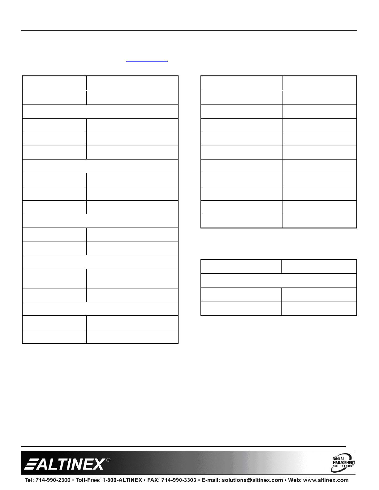
Features/Description MT302-121
General
Connectors
RS-232 5-pin terminal block (1)
Ethernet RJ45 (1)
Input Power IEC M (1)
Connectors (Front panel)
Ethernet RJ45 (1)
IR receiver
IR blaster
Compatibility
Cards All Digital MultiTasker Cards
Communication RS-232
Accessories Included
-Terminal block connector for
Hardware
Power Cord NEMA to IEC
RS-232
-Cable ties
Mechanical MT302-121
Available Slots 12
Width 17.4 in (442mm)
Depth 13 in (330mm)
Height 5.2 in (132mm)
Weight (without cards)
Back Panel Black
T° Operating 10°C-35°C
T° Maximum 50°C
Humidity 90% non-condensing
MTBF (calc.) 40,000hrs
Table 2. MT302-121 Mechanical
Electrical MT302-121
Enclosure
Power Input
85VAC - 264VAC
@ 50/60Hz
Optional Accessories
MT399-102
MT399-105 Package of 5 pcs blank MT card
Table 1. MT302-121 General
400-0675-001
Mounting ears with accessories
Maximum Power 300 W
Table 3. MT302-121 Electrical
2
Page 3

MT302-121
User’s Guide
5. About Your MT300-121
Basic foundation of Digital MultiTasker solutions
3U high, full rack wide
TCP/IP control
LCD display
ON/OFF button
IR receiver/IR blaster
Ethernet control (2 ports)
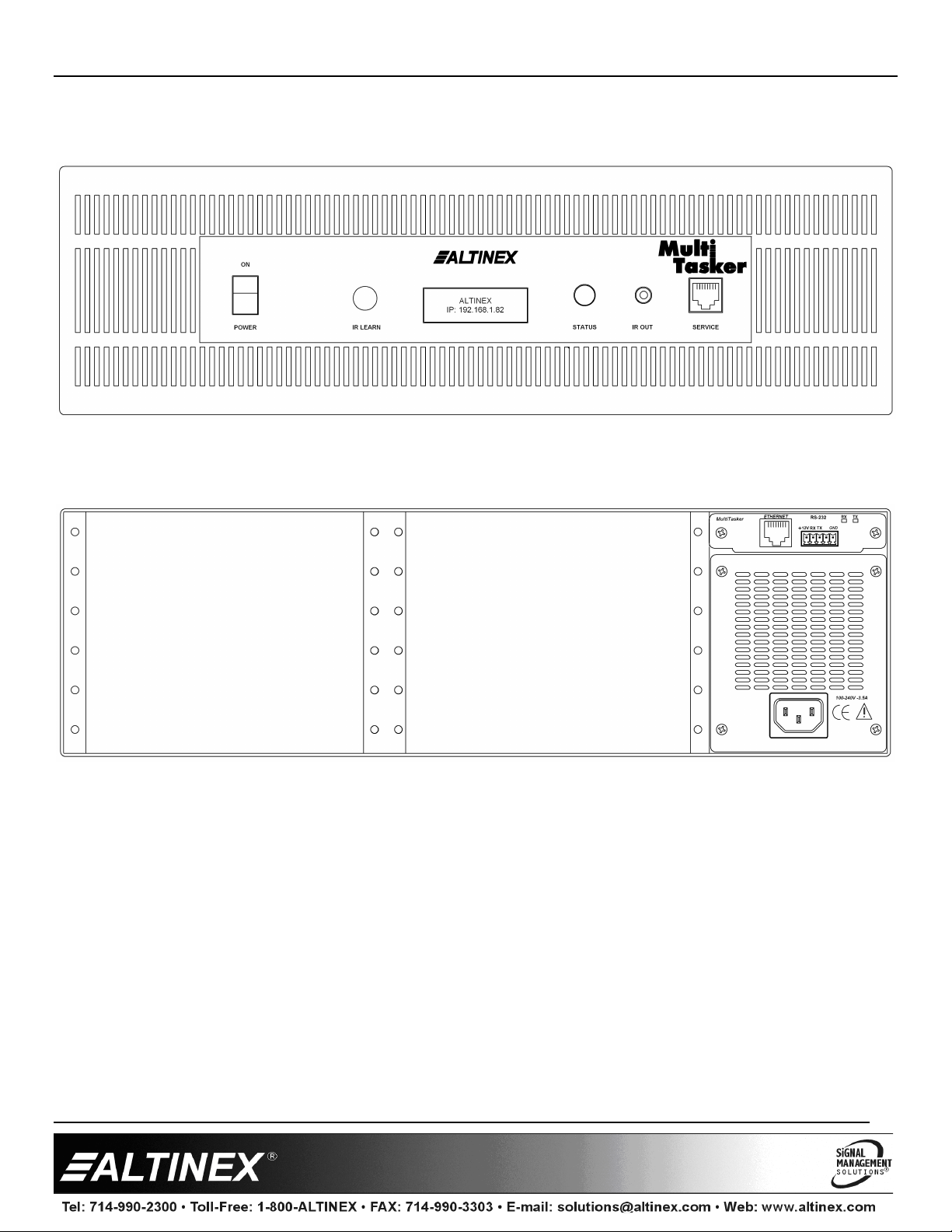
ALTINEX offers the 12-Slot enclosure MT302-121 for digital MultiTasker cards. In addition to the 12 available slots, the MT302-121
comes with 2 Ethernet ports and a front panel. The MultiTasker is controlled from the LAN or an easy to use web based interface.
The front panel has an LCD to display basic information about the system and cards installed; including the IP address of the
MultiTasker on the network.
The MultiTasker utilizes a simple ASCII based command set to control individual cards installed in the enclosure. Individual cards are
reference using their slot number as a unique identifier.
400-0675-001
3
Page 4
MT302-121
User’s Guide
400-0675-001
4
Page 5
MT302-121
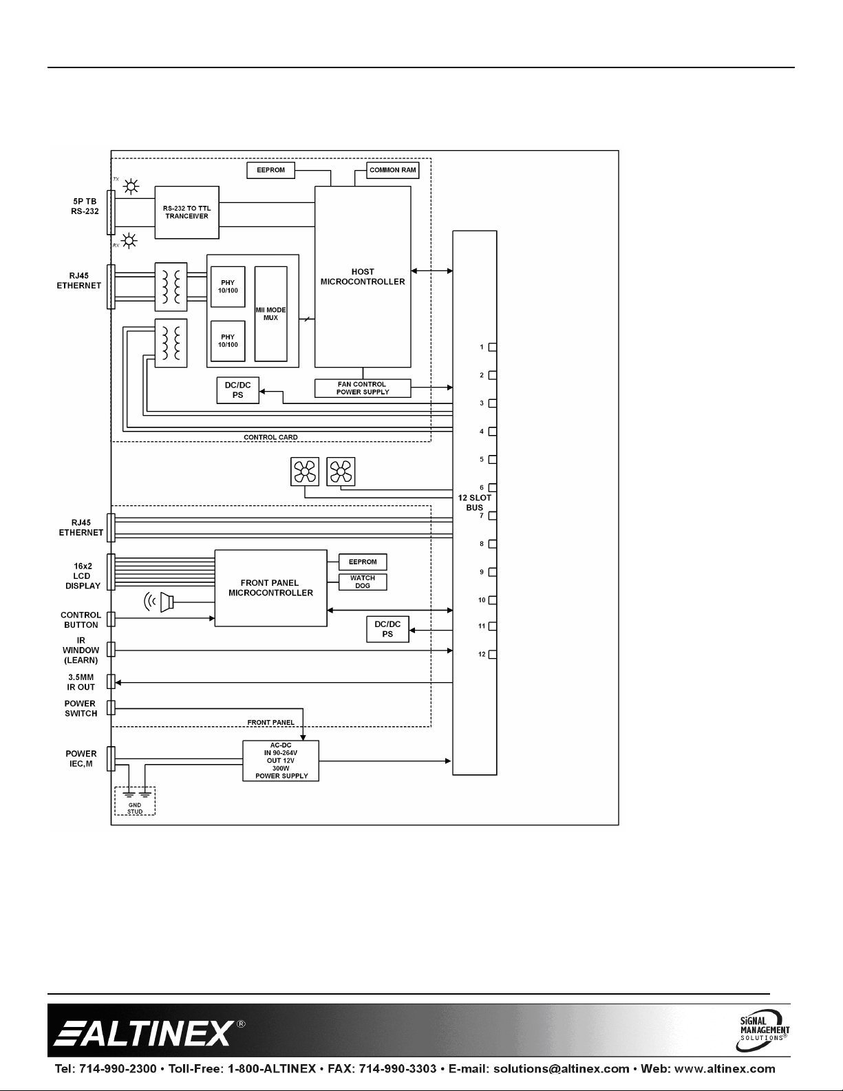
6. Application Diagrams
Diagram 1: Internal View
User’s Guide
400-0675-001
5
Page 6

MT302-121
User’s Guide
7. Operation
The MT302-121 has many advanced remote control
capabilities, which are accessible through TCP/IP
communication. Control is accomplished through a computer, a
control system, or any device capable of establishing a
standard TCP socket to the MT302-121s IP address.
7.1 Terminology
The terms below are used to increase the legibility of the
descriptions used in this section of the manual.
Cnn This term refers to a MultiTasker card where the
ID number is 2-digits; nn; typically the slot
number of the card, but may also be an assigned
value. Example: C01, C02, …. C20
string A string is one or more text characters that form a
command, describe output data, or refer to
incoming feedback.
feedback Feedback refers to data that is received from the
MultiTasker or any of the cards installed in the
enclosure.
7.2 LAN Connection
A computer or control system is used to control the cards in the
MultiTasker. Connect to the RJ45 on the front or rear of the
MT302-121.
7.3 TCP/IP Control
A third party controller or touch panel can be used to control
the MT302-121.The TCP/IP control commands provide full
control of the enclosure and the installed cards.
The control commands for the MT302-121 are in a simple
ASCII character format. Control can be achieved from the
same room, or remotely via the Ethernet using a CAT5/6 cable
terminated in the T568B standard.
7.4 Network Discover
The default IP address for all MT302-121s is 192.168.10.85 on
port 23 with DHCP set to automatic. If the switcher is on a
network, its IP is assigned automatically. If you connect the
switcher directly to a laptop, the IP is 192.168.10.85.
In order to find out the address assigned to switchers on a
network, broadcast the UDP discover command to the network
on port 30305. The discover command is as follows:
?Altinex
Send “?Altinex” in a single packet. Do not type the characters
individually or the command is ignored.
Any MT302-121s on the network respond with feedback similar
to the following single line:
[MT302-121,00:1E:C0:C9:6A:24,00023,
192:168:1:121,255:255:255;0:192:168:1:254]
The data inside the brackets includes the switcher
alias, switcher MAC address, and TCP/IP port, plus
the IP address, subnet mask, and gateway address
assigned to the switcher by the network.
Use this information to establish a TCP/IP connection to the
switcher for control and/or configuration.
7.5 Protocol
The protocol for the MT302-121 uses a simple ASCII character
format.
1. Brackets "[ ]" are part of the command for the
controller or plug-in card.
2. Use uppercase letters for all commands.
The MT302-121 has many advanced remote control
capabilities which are accessible through network
communication. Control can be accomplished using a
computer or a control system.
The enclosure and cards in a MultiTasker are capable of
performing various functions, as well as providing feedback to
the user or control system. Commands instruct a card to
perform specific actions, request status information, and some
do both simultaneously.
A command that does not request specific information will
generate feedback of "[ ]". The open bracket immediately
followed by a closed bracket indicates the card or unit received
a valid command. If the command requested information from
the card or enclosure, the feedback generated is the
acknowledgement of having received a valid command. Invalid
commands generate feedback indicating an error occurred.
Example: [ERC01]
7.5.1 Description of Commands
Each command consists of two parts: Function and Card.
[ Function , Card]
Example: [VERC03]
VER = Function
C03 = Card ID
The card ID is a unique identifier. It is equal to the enclosure
slot number.
400-0675-001
6
Page 7

MT302-121
User’s Guide
7.6 Commands
See the Command Summary (section 7.7) for a one-line
description of each command. The commands in this section
are organized as follows:
System Commands
Card Commands
System Commands
System commands provide information about the front panel,
control feedback, and provide access to overall enclosure
status and details.
1. [VER]
This command displays the current version of the firmware.
Command Format: [VER]
2. [RES]
The [RES] command resets the enclosure. The controller
and all cards in the enclosure will be reset to their power up
settings.
3. [?]
This command displays general information about the
MultiTasker and the cards installed.
Command Format: [?]
Example:
Send [?] and receive the following feedback:
[(MT302-121)(MT103-121C02)(MT103-122C03)
(MT103-123C04)]
MT302-121 = Panel model number
MT305-804C04 = An MT305-804 is in slot 4
MT312-104C06 = An MT312-104 is in slot 6
MT306-101C08 = An MT306-101 is in slot 8
Card Commands
Card commands provide information about individual cards. All
cards share some basic commands like version, model
number, etc. The commands listed in this section include
common commands that are shared by different cards and
may not apply to all cards. Commands specific to individual
cards are available in the card’s user guide.
4. [?C]
This command displays general information about a card
and its status.
Command Format: [?Cn]
Cn = Card ID (n = # from 1 to max slots)
Example:
The MT305-804 switcher card in slot 4 is on, input 1 is
connected to outputs 1, 2, and 3 with input 2 connected to
output 4. There are signals present on inputs 1 through 4
only. Send the command [?C2] to receive the following
status:
[(MT305-804C04)(VR690-0424-001C04)(MA1112C04)(
SI11110000C04)]
All status feedback is enclosed in brackets, "[ ]". Each data
field within the status is enclosed in parentheses. The first
two characters identify the status type. The last three
characters are the card’s ID.
MT305-804 = Card model number
VR690-0424-001 = Firmware version
MA1112 = Matrix output connections 1~4
SI11110000 = Signal detect (1=yes)
5. [VERCnn]
This command displays the card firmware version.
Command Format: [VERCnn]
Cnn = Card ID (n = # from 01 to max slots)
Example:
Request the firmware version of the MT312-104 switcher
card in slot 6 by sending [VERC06] and receive feedback
similar to the following:
[690-0425-001C06]
400-0675-001
7
Page 8

MT302-121
User’s Guide
6. [IxOyCnn]
This command connects an input to one or all outputs on a
matrix switcher card.
Command Format: [IxOyCnn]
nn = Card ID (nn = # from 01 to max slots)
x = Input (x = Input no.)
y = Output (y = Output no., * = all outputs)
Example:
Connect Input 1 to Output 2 of the MT305-804 card in slot
4 by sending [I1O2C04]. If the command is successful, the
following feedback is received:
[ ]
7.7 Summary of Commands
System Commands
1) [VER] Display firmware version
2) [RES] Reset the system
3) [?] Display system status
Card Commands
4) [?C] Display card status
5) [VER] Display firmware version
6) [IxOy] Connect input to output
7.8 Control Software
AVSnap control software is available from the ALTINEX
website at www.altinex.com in the Software section.
400-0675-001
8
Page 9
MT302-121
User’s Guide
8. Troubleshooting Guide
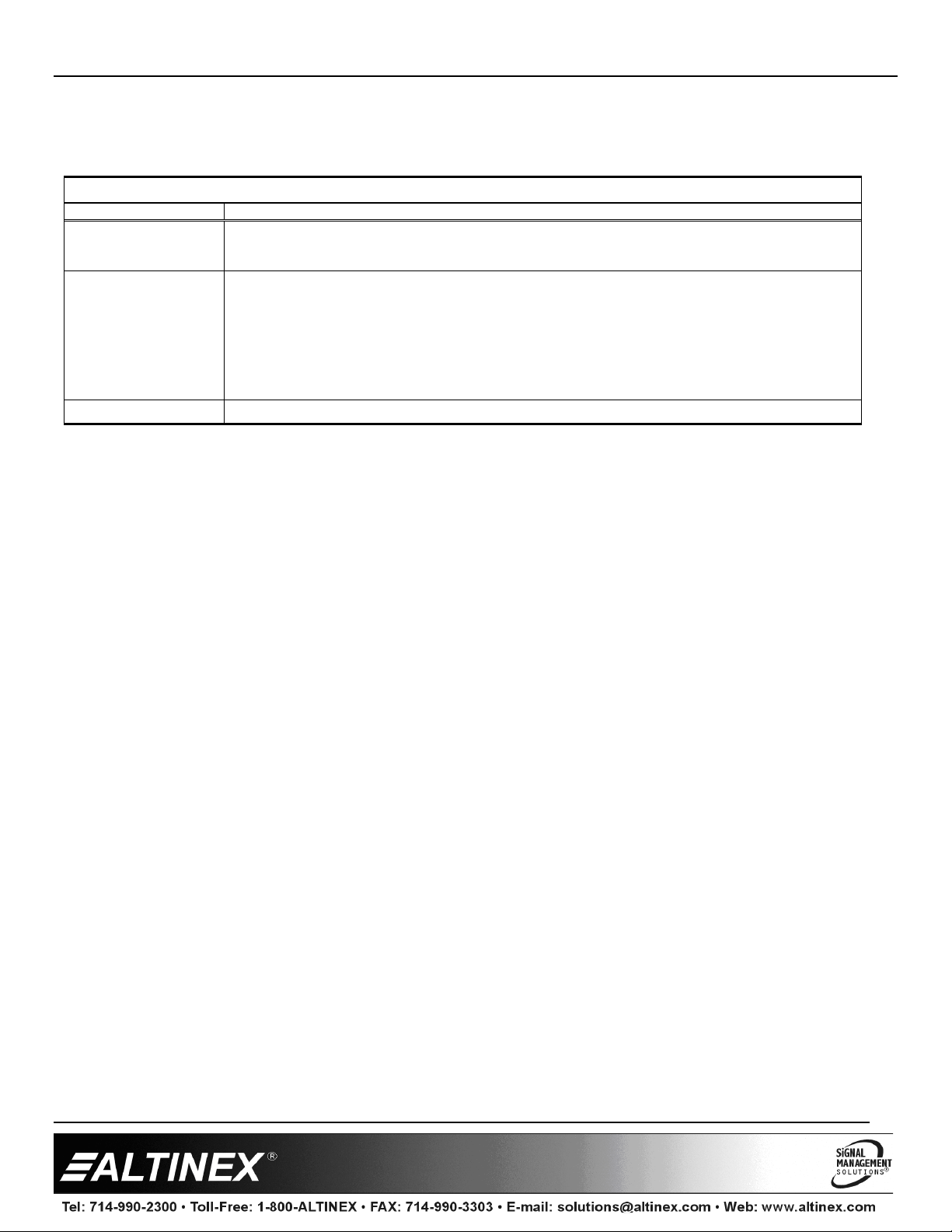
We have carefully tested and have found no problems in the supplied MT302-121; however, we would like to offer suggestions for the
following:
MultiTasker Enclosure
Symptom Resolution
1. Make sure the enclosure is plugged into a working AC outlet.
Enclosure Not Working
Card Is Not Working
System Failure Please call the Altinex Customer Service Department at (714) 990-2300 to have the unit repaired.
2. The input power voltage is incorrect. Make sure the AC input power is within the range of
85-264VAC. If the enclosure still has a problem, call Altinex at (714) 990-2300.
1. The card cage slot has a problem. If the slot was damaged, the card may work in other slots. If
other slots work, the problem is the card cage slot. The card cage may require service. Call
Altinex at (714) 990-2300.
2. Take any other known good card and plug it into the slot in question. If the card works, the
original card may be the source of the problem. Call Altinex at (714) 990-2300.
3. The input power voltage is incorrect. Make sure that the input power range is within 85-264 VAC
and also make sure that the power is connected to the input power connector. If there is still a
problem, call Altinex at 714 990-2300.
400-0675-001
9
 Loading...