

Page 1

Video and Image Processing Suite User
Guide
Subscribe
Send Feedback
UG-VIPSUITE
2015.05.04
101 Innovation Drive
San Jose, CA 95134
www.altera.com
Page 2

TOC-2
Contents
Video and Image Processing Suite Overview..................................................... 1-1
Interfaces............................................................................................................. 2-1
Release Information.....................................................................................................................................1-3
Device Family Support................................................................................................................................1-4
Latency...........................................................................................................................................................1-5
In-System Performance and Resource Guidance....................................................................................1-8
Stall Behavior and Error Recovery.......................................................................................................... 1-12
Video Formats..............................................................................................................................................2-2
Avalon-ST Video Protocol..........................................................................................................................2-7
Video Data Packets........................................................................................................................2-11
Static Parameters of Video Data Packets....................................................................................2-11
Control Data Packets.....................................................................................................................2-15
Ancillary Data Packets.................................................................................................................. 2-19
User-Defined and Altera-Reserved Packets...............................................................................2-19
Packet Propagation........................................................................................................................2-19
Transmission of Avalon-ST Video Over Avalon-ST Interfaces..............................................2-20
Packet Transfer Examples.............................................................................................................2-21
Avalon-MM Slave Interfaces....................................................................................................................2-25
Specification of the Type of Avalon-MM Slave Interfaces.......................................................2-27
Avalon-MM Master Interfaces.................................................................................................................2-28
Specification of the Type of Avalon-MM Master Interfaces....................................................2-28
Buffering of Non-Image Data Packets in Memory............................................................................... 2-29
Getting Started.................................................................................................... 3-1
Clocked Video Interface IP Cores.......................................................................4-1
Altera Corporation
IP Catalog and Parameter Editor...............................................................................................................3-1
Specifying IP Core Parameters and Options................................................................................3-2
Installing and Licensing IP Cores..............................................................................................................3-2
OpenCore Plus IP Evaluation........................................................................................................ 3-3
Control Port..................................................................................................................................................4-1
Clocked Video Input Format Detection...................................................................................................4-2
Interrupts.......................................................................................................................................... 4-5
Clocked Video Output Video Modes........................................................................................................4-5
Interrupts.......................................................................................................................................... 4-9
Generator Lock.............................................................................................................................................4-9
Underflow and Overflow..........................................................................................................................4-11
Timing Constraints....................................................................................................................................4-12
Handling Ancillary Packets......................................................................................................................4-12
Page 3

TOC-3
Modules for Clocked Video Input II IP Core........................................................................................4-15
Clocked Video Interface Parameter Settings......................................................................................... 4-18
Clocked Video Interface Signals..............................................................................................................4-26
Clocked Video Interface Control Registers............................................................................................4-36
2D FIR Filter IP Core.......................................................................................... 5-1
Calculation Precision...................................................................................................................................5-1
Coefficient Precision....................................................................................................................................5-2
Result to Output Data Type Conversion..................................................................................................5-2
2D FIR IP Core Parameter Settings...........................................................................................................5-2
2D FIR Filter Signals....................................................................................................................................5-4
2D FIR Filter Control Registers................................................................................................................. 5-5
Video Mixing IP Cores........................................................................................6-1
Alpha Blending.............................................................................................................................................6-2
Video Mixing Parameter Settings..............................................................................................................6-3
Video Mixing Signals...................................................................................................................................6-5
Video Mixing Control Registers................................................................................................................6-8
Chroma Resampler IP Core................................................................................ 7-1
Horizontal Resampling (4:2:2)...................................................................................................................7-1
4:4:4 to 4:2:2......................................................................................................................................7-2
4:2:2 to 4:4:4......................................................................................................................................7-2
Vertical Resampling (4:2:0)........................................................................................................................ 7-3
Chroma Resampler Parameter Settings....................................................................................................7-4
Chroma Resampler Signals.........................................................................................................................7-5
Video Clipping IP Cores..................................................................................... 8-1
Video Clipping Parameter Settings...........................................................................................................8-1
Video Clipping Signals................................................................................................................................8-4
Video Clipping Control Registers..............................................................................................................8-6
Color Plane Sequencer IP Core...........................................................................9-1
Combining Color Patterns..........................................................................................................................9-1
Rearranging Color Patterns........................................................................................................................9-2
Splitting and Duplicating............................................................................................................................9-3
Subsampled Data..........................................................................................................................................9-4
Color Plane Sequencer Parameter Settings.............................................................................................. 9-4
Color Plane Sequencer Signals...................................................................................................................9-5
Color Space Conversion IP Cores.....................................................................10-1
Input and Output Data Types..................................................................................................................10-2
Color Space Conversion............................................................................................................................10-2
Result of Output Data Type Conversion................................................................................................10-3
Altera Corporation
Page 4

TOC-4
Color Space Conversion Parameter Settings..........................................................................................10-4
Color Space Conversion Signals.............................................................................................................. 10-8
Color Space Conversion Control Registers..........................................................................................10-10
Control Synchronizer IP Core.......................................................................... 11-1
Using the Control Synchronizer IP Core............................................................................................... 11-2
Control Synchronizer Parameter Settings..............................................................................................11-4
Control Synchronizer Signals...................................................................................................................11-5
Control Synchronizer Control Registers................................................................................................11-6
Deinterlacing IP Cores......................................................................................12-1
Deinterlacing Methods..............................................................................................................................12-2
Bob with Scanline Duplication.....................................................................................................12-3
Bob with Scanline Interpolation..................................................................................................12-3
Weave.............................................................................................................................................. 12-3
Motion-Adaptive........................................................................................................................... 12-3
Pass-Through Mode for Progressive Frames.............................................................................12-6
Frame Buffering......................................................................................................................................... 12-6
Frame Rate Conversion.............................................................................................................................12-8
Bandwidth Requirement Calculations for 10-bit YCbCr Video.........................................................12-8
Behavior When Unexpected Fields are Received..................................................................................12-9
Handling of Avalon-ST Video Control Packets..................................................................................12-10
Deinterlacing Parameter Settings..........................................................................................................12-10
Deinterlacing Signals...............................................................................................................................12-17
Deinterlacing Control Registers............................................................................................................ 12-23
Design Guidelines for Broadcast Deinterlacer IP Core......................................................................12-30
Tuning Motion Shift....................................................................................................................12-32
Active Video Threshold Adjustment........................................................................................12-32
Frame Reader IP Core.......................................................................................13-1
Frame Buffer IP Cores.......................................................................................14-1
Altera Corporation
Single-Cycle Color Patterns......................................................................................................................13-1
Frame Reader Output Pattern and Memory Organization..................................................................13-2
Frame Reader Parameter Settings............................................................................................................13-3
Frame Reader Signals................................................................................................................................ 13-3
Frame Reader Control Registers..............................................................................................................13-5
Double Buffering........................................................................................................................................14-2
Triple Buffering..........................................................................................................................................14-2
Locked Frame Rate Conversion...............................................................................................................14-3
Handling of Avalon-ST Video Control Packets....................................................................................14-3
Color Format..............................................................................................................................................14-4
Frame Buffer Parameter Settings.............................................................................................................14-5
Frame Buffer Signals..................................................................................................................................14-9
Frame Buffer Control Registers.............................................................................................................14-13
Page 5

TOC-5
Gamma Corrector IP Core................................................................................15-1
Gamma Corrector Parameter Settings....................................................................................................15-1
Gamma Corrector Signals........................................................................................................................ 15-2
Gamma Corrector Control Registers......................................................................................................15-3
Interlacer IP Core..............................................................................................16-1
Interlacer Parameter Settings...................................................................................................................16-2
Interlacer Signals........................................................................................................................................16-2
Interlacer Control Registers..................................................................................................................... 16-4
Scaler II IP Core.................................................................................................17-1
Nearest Neighbor Algorithm................................................................................................................... 17-1
Bilinear Algorithm.....................................................................................................................................17-2
Bilinear Algorithmic Description................................................................................................17-2
Polyphase and Bicubic Algorithm...........................................................................................................17-3
Double-Buffering...........................................................................................................................17-5
Polyphase Algorithmic Description............................................................................................17-6
Choosing and Loading Coefficients............................................................................................17-6
Edge-Adaptive Scaling Algorithm...........................................................................................................17-8
Scaler II Parameter Settings......................................................................................................................17-9
Scaler II Signals........................................................................................................................................ 17-12
Scaler II Control Registers......................................................................................................................17-14
Video Switching IP Cores..................................................................................18-1
Mixer Layer Switching.............................................................................................................................. 18-2
Video Switching Parameter Settings.......................................................................................................18-3
Video Switching Signals............................................................................................................................18-3
Video Switching Control Registers......................................................................................................... 18-5
Test Pattern Generator IP Cores.......................................................................19-1
Test Pattern.................................................................................................................................................19-1
Generation of Avalon-ST Video Control Packets and Run-Time Control.......................................19-3
Test Pattern Generator Parameter Settings............................................................................................19-4
Test Pattern Generator Signals................................................................................................................ 19-6
Test Pattern Generator Control Registers..............................................................................................19-8
Trace System IP Core........................................................................................ 20-1
Trace System Parameter Settings.............................................................................................................20-2
Trace System Signals................................................................................................................................. 20-3
Operating the Trace System from System Console...............................................................................20-4
Loading the Project and Connecting to the Hardware.............................................................20-5
Trace Within System Console......................................................................................................20-6
TCL Shell Commands................................................................................................................... 20-7
Altera Corporation
Page 6

TOC-6
Avalon-ST Video Monitor IP Core...................................................................21-1
Packet Visualization.................................................................................................................................. 21-2
Monitor Settings........................................................................................................................................ 21-3
Avalon-ST Video Monitor Parameter Settings......................................................................................21-3
Avalon-ST Video Monitor Signals.......................................................................................................... 21-4
Avalon-ST Video Monitor Control Registers........................................................................................21-6
Avalon-ST Video Verification IP Suite..............................................................A-1
Avalon-ST Video Class Library.................................................................................................................A-2
Running the Tests....................................................................................................................................... A-7
Video File Reader Test................................................................................................................. A-10
Constrained Random Test...........................................................................................................A-15
Complete Class Reference........................................................................................................................A-19
c_av_st_video_control ................................................................................................................ A-19
c_av_st_video_data ......................................................................................................................A-21
c_av_st_video_file_io ..................................................................................................................A-21
c_av_st_video_item ..................................................................................................................... A-26
c_av_st_video_source_sink_base .............................................................................................. A-27
c_av_st_video_sink_bfm_’SINK ................................................................................................A-28
c_av_st_video_source_bfm_’SOURCE .....................................................................................A-29
c_av_st_video_user_packet ........................................................................................................A-30
c_pixel ............................................................................................................................................A-31
Raw Video Data Format...........................................................................................................................A-31
Choosing the Correct Deinterlacer.................................................................... B-1
Cadence Detection and Reverse Pulldown in the Deinterlacer II IP Core..........................................B-3
Additional Information......................................................................................C-1
Document Revision History......................................................................................................................C-1
How to Contact Altera............................................................................................................................... C-5
Altera Corporation
Page 7

2015.05.04
www.altera.com
101 Innovation Drive, San Jose, CA 95134
Video and Image Processing Suite Overview
1
UG-VIPSUITE
Subscribe
Send Feedback
The Altera® Video and Image Processing Suite collection of IP cores ease the development of video and
image processing designs.
You can use these IP cores in a wide variety of image processing and display applications.
Attention: Altera has scheduled the following IP cores for product obsolescence and will discontinue
support for it.
• Clipper
• Test Pattern Generator
Altera recommends that you do not use these IP cores in new designs. For more information
about Altera’s current IP offering, visit the Altera Intellectual Property web page.
Table 1-1: Video and Image Processing Suite IP Core Features
The table lists the IP cores in the Video and Image Processing Suite.
IP Core
Pixels in Parallel 4:2:2 Support Interlaced
Feature Support
2D FIR Filter No No No
Alpha Blending
No Yes Yes
Mixer
(1)
Chroma Resampler No Yes No
Clipper No Yes Yes
Clipper II Yes Yes Yes
Clocked Video
No Yes Yes
(2)
(2)
Input (CVI)
Clocked Video
Yes Yes Yes
Input II (CVI II)
(1)
The IP core accepts interlaced input streams but they are treated as progressive inputs. Consequently, you
require external logic to synchronize the input fields and prevent the mixing of F0 fields with F1 fields.
(2)
The IP core accepts interlaced inputs but they are treated as progressive inputs.
©
2015 Altera Corporation. All rights reserved. ALTERA, ARRIA, CYCLONE, ENPIRION, MAX, MEGACORE, NIOS, QUARTUS and STRATIX words and logos are
trademarks of Altera Corporation and registered in the U.S. Patent and Trademark Office and in other countries. All other words and logos identified as
trademarks or service marks are the property of their respective holders as described at www.altera.com/common/legal.html. Altera warrants performance
of its semiconductor products to current specifications in accordance with Altera's standard warranty, but reserves the right to make changes to any
products and services at any time without notice. Altera assumes no responsibility or liability arising out of the application or use of any information,
product, or service described herein except as expressly agreed to in writing by Altera. Altera customers are advised to obtain the latest version of device
specifications before relying on any published information and before placing orders for products or services.
ISO
9001:2008
Registered
Page 8

1-2
Video and Image Processing Suite Overview
UG-VIPSUITE
2015.05.04
IP Core
Clocked Video
Pixels in Parallel 4:2:2 Support Interlaced
No Yes Yes
Feature Support
Output (CVO)
Clocked Video
Yes Yes Yes
Output II (CVO II)
Color Plane
No Yes Yes
Sequencer
Color Space
No No Yes
Converter (CSC)
Color Space
Yes No Yes
Converter II (CSC
II)
Control Synchron‐
No Yes Yes
izer
Deinterlacer No Yes Yes
Deinterlacer II No Yes Yes
Broadcast Deinter‐
No Yes Yes
lacer
Frame Buffer No Yes Yes
Frame Buffer II Yes Yes Yes
Frame Reader No Yes Yes
Gamma Corrector No Yes Yes
Interlacer No Yes Yes
Mixer II Yes Yes Yes
Scaler II No Yes Yes
(3)
(1)
(2)
Switch No Yes Yes
Switch II Yes Yes Yes
Test Pattern
No Yes Yes
(4)
Generator
Test Pattern
Yes Yes Yes
(4)
Generator II
(3)
The IP core either discards or propagates without change the interlaced data if you select Pass-through
mode in the parameter editor.
(4)
For interlaced data NTSC, mismatched line counts of F0 and F1 are not supported.
Altera Corporation
Video and Image Processing Suite Overview
Send Feedback
Page 9

UG-VIPSUITE
2015.05.04
Release Information
The following table lists information about this release of the Video and Image Processing Suite.
Table 1-2: Release Information
Item Description
Version 15.0
Release Date May 2015
Release Information
1-3
Ordering
Code
Product ID
IPS-VIDEO (Video and Image Processing Suite)
00B3 (2D FIR Filter)
00B5 (Alpha Blending
Mixer)
0115 (Mixer II)
00D1 (Avalon-ST Video
Monitor)
00B1 (Chroma Resampler)
00C8 (Clipper)
0115 (Clipper II)
00C4 (Clocked Video
Input)
00F1 (Clocked Video
Input II)
00C5 (Clocked Video
Output)
00EF (Clocked Video
Output II)
00C9 (Color Plane
Sequencer)
0003 (Color Space
Converter)
00F2 (Color Space
Converter II)
00D0 (Control Synchron‐
izer)
00B6 (Deinterlacer)
00EE (Deinterlacer II)
0114 (Broadcast Deinter‐
lacer)
0112 (Frame Reader)
00C3 (Frame Buffer)
0115 (Frame Buffer II)
00B2 (Gamma Corrector)
00DC (Interlacer)
00E9 (Scaler II)
00CF (Switch)
00F4 (Switch II)
00CA (Test Pattern Generator)
00F3 (Test Pattern Generator II)
00ED (Trace System)
Vendor ID 6AF7
Altera verifies that the current version of the Quartus II software compiles the previous version of each IP
core, if this IP core was included in the previous release. Any exceptions to this verification are reported in
the MegaCore IP Library Release Notes and Errata. Altera does not verify compilation with IP core
versions older than the previous release.
Related Information
• Altera IP Library Release Notes
• Errata for VIP Suite in the Knowledge Base
Video and Image Processing Suite Overview
Send Feedback
Altera Corporation
Page 10

1-4
Device Family Support
Device Family Support
The table below lists the device support information for the Video and Image Processing Suite IP cores.
Table 1-3: Device Family Support
Device Family Support
Arria II GX / Arria II GZ Final
Arria V Final
Arria 10 Final—Supports only the following IP cores:
• Avalon-ST Video Monitor
• Broadcast Deinterlacer
• Clipper II
• Clocked Video Input
• Clocked Video Input II
• Clocked Video Output
• Clocked Video Output II
• Color Space Converter II
• Deinterlacer II
• Frame Buffer II
• Mixer II
• Scaler II
• Switch II
• Test Pattern Generator II
UG-VIPSUITE
2015.05.04
Cyclone IV ES / Cyclone IV GX Final
Cyclone V Final
MAX 10 Final
Stratix IV Final
Stratix V Final
Other device families No support
Related Information
What's New for IP in Quartus II Software
Provides more information about the support levels and current status.
Altera Corporation
Video and Image Processing Suite Overview
Send Feedback
Page 11

UG-VIPSUITE
2015.05.04
Latency
Latency
You can use the latency information to predict the approximate latency between the input and the output
of your video processing pipeline.
The latency is described using one or more of the following measures:
• the number of progressive frames
• the number of interlaced fields
• the number of lines when less than a field of latency
• a small number of cycles O (cycles)
Note: O refers to a small number of clock cycles, and is not of zero value.
The latency is measured with the assumption that the IP core is not being stalled by other functions on the
data path; (the output ready signal is high).
Table 1-4: Video and Image Processing Suite Latency
The table below lists the approximate latency from the video data input to the video data output for typical usage
modes of the Video and Image Processing Suite IP cores.
IP Core Mode Latency
1-5
2D FIR Filter Latency Filter size: N × N (N–1) lines + O (cycles)
Alpha Blending Mixer/ Mixer II All modes O (cycles)
Input format: 4:2:2; Output
O (cycles)
format: 4:4:4
Chroma Resampler
Input format: 4:2:0; Output
1 line + O (cycles)
format: 4:4:4 or 4:2:2
Clipper/ Clipper II All modes O (cycles)
Clocked Video Input
Note: Add 1 cycle if you turned
on the Allow color planes
in sequence input
• Synchronization signals:
Embedded in video
• Video in and out use the
same clock: On
8 cycles
parameter.
• Synchronization signals: On
5 cycles
separate wires
• Video in and out use the
same clock: On
Video and Image Processing Suite Overview
Send Feedback
Altera Corporation
Page 12

1-6
Latency
UG-VIPSUITE
2015.05.04
IP Core Mode Latency
• Synchronization signals:
10 cycles
Embedded in video
• Video in and out use the
same clock: On
Clocked Video Input II
• Synchronization signals: On
6 cycles
separate wires
• Video in and out use the
same clock: On
Clocked Video Output/
Clocked Video Output II
Note: Add 1 cycle if you turned
on the Allow color planes
in sequence input
All modes with video in and out
use the same clock: On
3 cycles
Note: Note: Minimum latency
case when video input
and output rates are
synchronized.
parameter.
Color Plane Sequencer All modes O (cycles)
Color Space Converter (CSC)/
All modes O (cycles)
Color Space Converter II
Control Synchronizer All modes O (cycles)
Altera Corporation
Video and Image Processing Suite Overview
Send Feedback
Page 13

UG-VIPSUITE
2015.05.04
Latency
IP Core Mode Latency
1-7
Deinterlacer
• Method: Bob
• Frame buffering: None
• Method: Motion-adaptive or
Weave
• Frame buffering: Double or
triple buffering with rate
conversion
• Output frame rate: As input
frame rate
• Method: Motion-adaptive or
Weave
• Frame buffering: Double or
triple buffering with rate
conversion
• Output frame rate: As input
field rate
• Method: All
• Frame buffering: Double or
triple buffering with rate
conversion
• Passthrough mode
(propagate progressive
frames unchanged): On.
O (cycles)
1 frame + O (lines)
1 field + O (lines)
1 frame + O (lines)
Deinterlacer II
Video and Image Processing Suite Overview
• Method: Motion-adaptive
• Frame buffering: None
• Output frame rate: As input
field rate
2 lines
Altera Corporation
Send Feedback
Page 14

1-8
In-System Performance and Resource Guidance
IP Core Mode Latency
UG-VIPSUITE
2015.05.04
• Method: Motion-adaptive
1 field + 2 lines
• Frame buffering: None
• Output frame rate: As input
field rate
• Method: Motion-adaptive,
1 field + 2 lines, or 2 lines
video-over-film mode
Broadcast Deinterlacer
• Frame buffering: 3 input
fields are buffered
• Output frame rate: As input
field rate
40% to 60% (depending on
phasing) of the time, the core
performs a weave forward so
there is no initial field of latency.
Frame Buffer/ Frame Buffer II All modes 1 frame + O (lines)
Frame Reader No latency issues.
Gamma Corrector All modes O (cycles)
Interlacer All modes O (cycles)
Scaler II
• Scaling algorithm: Polyphase
• Number of vertical taps: N
Switch/ Switch II All modes 2 cycles
Test Pattern Generator/
No latency issues.
Test Pattern Generator II
In-System Performance and Resource Guidance
The performance and resource data provided for your guidance.
Run your own synthesis and f
Note:
ments.
trials to confirm the listed IP cores meet your system require‐
MAX
(N–1) lines + O (cycles)
Altera Corporation
Video and Image Processing Suite Overview
Send Feedback
Page 15

UG-VIPSUITE
2015.05.04
In-System Performance and Resource Guidance
Table 1-5: Performance and Resource Data Using Arria V Devices
The following data are obtained through a 4K test design example using an Arria V device (5AGXFB3H4F35C4).
1-9
The general settings for the design is 8 bits per color plane; 2 pixels in parallel. The target f
IP Core Configuration ALM RAM DSP
Mixer II
• Number of color planes in parallel = 3
1,591 0 0
• Inputs = 4
• Output = 1
• Internal Test Pattern Generator
Clocked Video
Input II
• Number of color planes in parallel = 3
• Sync signals = On separate wires
540 26 0
• Pixel FIFO size = 4096 pixels
• Use control port = On
Clocked Video
Output II
• Number of color planes in parallel = 3
• Sync signals = On separate wires
2,504 49 0
• Pixel FIFO size = 4096 pixels
• Use control port = On
• Run-time configurable video modes = 4
Color Space
Converter II
• Run-time control = On
• Color model conversion = RGb to YCbCr
1,515 0 18
is 148.5 MHz.
MAX
Broadcast Deinter‐
lacer
Frame Buffer II
Test Pattern
Generator II
• Number of color planes in parallel = 2
• Avalon-MM master local ports width =
256
• FIFO depths = 512
• Run-time control = Off
• Number of color planes in parallel = 2
• Avalon-MM master ports width = 256
• Read/write FIFO depth = 128
• Frame dropping = On
• Frame repeating = On
• Color space = RGB
• Run-time control of image size = On
11,516 145 34
1,472 19 0
135 0 0
Video and Image Processing Suite Overview
Send Feedback
Altera Corporation
Page 16

1-10
In-System Performance and Resource Guidance
UG-VIPSUITE
2015.05.04
Table 1-6: Performance and Resource Data Using Cyclone V Devices
The following data are obtained through a video design example using a Cyclone V device (5CGTFD9E5F35C7).
The general setting for the design is 8 bits per color plane. The target f
IP Core Configuration ALM RAM DSP
2D FIR Filter
• Number of color planes in sequence = 3
• Filter size = 3×3
• Runtime control = On
• Integer bits = 4
• Fractional bits = 3
Avalon-ST Video
Monitor
Avalon-ST Video
Monitor
Alpha Blending
Mixer
• Number of color planes in parallel = 3
• Capture video pixel data = On
• Number of color planes in parallel = 3
• Capture video pixel data = Off
• Number of color planes in parallel = 3
• Number of layers being mixed = 5
• Alpha blending = On
Chroma
Resampler
• 4:2:2, number of color planes in parallel
(din) = 2
• 4:4:4, number of color planes in parallel
(dout) = 3
• Horizontal filtering algorithm = Filtered
• Luma adaptive = On
is 100 MHz.
MAX
581 10 3
1,035 10 0
479 9 0
1,324 1 24
591 0 0
Clipper II
Clocked Video
Input
Clocked Video
Input
Altera Corporation
• Number of pixels (color planes) in parallel
= 3
• Clipping method = Rectangle
• Enable runtime control of clipping
parameters = On
• Number of color planes in parallel = 3
• Sync signals = On separate wires
• Pixel FIFO size = 2048 pixels
• Use control port = On
• Number of color planes in sequence = 2
• Sync signals = Embedded
• Pixel FIFO size = 2048 pixels
• Use control port = On
402 0 0
257 13 0
317 9 0
Video and Image Processing Suite Overview
Send Feedback
Page 17

UG-VIPSUITE
2015.05.04
In-System Performance and Resource Guidance
IP Core Configuration ALM RAM DSP
1-11
Clocked Video
Output
Color Plane
Sequencer
Color Space
Converter
Deinterlacer II
• Number of color planes in parallel = 3
• Sync signals = On separate wires
• Pixel FIFO size = 1024 pixels
• Use control port = On
• Run-time configurable video modes = 1
• din0: Color planes in parallel = 4
• dout0: Color planes in parallel = 3
• dout1: Color planes in parallel = 1
• Color plane configuration = Three color
planes in parallel
• Run-time control = Off
• Color model conversion = CbCrY': SDTV
to Computer B'G'R'
• Coefficients integer bits = 2
• Summands integer bits = 9
• Coefficient and summand fractional bits =
8
• Number of color planes in parallel = 3
• Deinterlace algorithm = Motion adaptive
• Cadence detection algorithm = 3:2 detector
• Avalon-MM master local ports width =
128
• FIFO depths = 64
512 5 0
104 0 0
284 0 9
3,655 67 3
Frame Buffer
• Number of color planes in parallel = 3
• Avalon-MM master ports width = 128
• Read/write FIFO depth = 64
• Frame dropping = On
• Frame repetition = On
Frame Reader
• Number of color planes in parallel = 4
• Avalon-MM master port width = 128
• Read master FIFO depth = 64
• Use separate clocks for the Avalon-MM
master interfaces = On
Gamma Corrector Number of color planes in parallel = 3 142 3 0
Video and Image Processing Suite Overview
Send Feedback
1,084 19 0
756 6 0
Altera Corporation
Page 18

1-12
Stall Behavior and Error Recovery
IP Core Configuration ALM RAM DSP
UG-VIPSUITE
2015.05.04
Scaler II
• Symbols in parallel = 3
• Scaling algorithm = Polyphase
• Enable run-time control of input/output
frame size = On
• Vertical/horizontal filter taps = 4
• Vertical/horizontal filter phases = 14
Test Pattern
Generator
Trace System
• Color space = RGB
• Run-time control of image size = Off
• Buffer size = 8192
• Bit width of capture interface(s) = 32
• Number of inputs = 2
Stall Behavior and Error Recovery
The Video and Image Processing Suite IP cores do not continuously process data. Instead, they use flowcontrolled Avalon-ST interfaces, which allow them to stall the data while they perform internal
calculations.
During control packet processing, the IP cores might stall frequently and read or write less than once per
clock cycle. During data processing, the IP cores generally process one input or output per clock cycle.
There are, however, some stalling cycles. Typically, these are for internal calculations between rows of
image data and between frames/fields.
1,010 12 12
65 0 0
1,224 12 0
When stalled, an IP core indicates that it is not ready to receive or produce data. The time spent in the
stalled state varies between IP cores and their parameterizations. In general, it is a few cycles between rows
and a few more between frames.
If data is not available at the input when required, all of the IP cores stall and do not output data. With the
exceptions of the Deinterlacer and Frame Buffer in double or triple-buffering mode, none of the IP cores
overlap the processing of consecutive frames. The first sample of frame F + 1 is not input until after the IP
cores produce the last sample of frame F.
When the IP cores receive an endofpacket signal unexpectedly (early or late), the IP cores recover from
the error and prepare for the next valid packet (control or data).
Altera Corporation
Video and Image Processing Suite Overview
Send Feedback
Page 19

UG-VIPSUITE
2015.05.04
Stall Behavior and Error Recovery
IP Core Stall Behavior Error Recovery
1-13
2D FIR Filter
• Has a delay of a little more than N–1
lines between data input and output in
the case of a N×N 2D FIR Filter.
• Delay caused by line buffering internal
to the IP core.
• Resolution is not configurable at run
time.
• Does not read the control packets
passed through it.
An error condition occurs if an
endofpacket signal is received too early
or too late for the compile time
configured frame size. In either case, the
2D FIR Filter always creates output
video packets of the configured size.
• If an input video packet has a late
endofpacket signal, then the extra
data is discarded.
• If an input video packet has an early
endofpacket signal, then the video
frame is padded with an undefined
combination of the last input pixels.
Video and Image Processing Suite Overview
Send Feedback
Altera Corporation
Page 20

1-14
Stall Behavior and Error Recovery
IP Core Stall Behavior Error Recovery
UG-VIPSUITE
2015.05.04
Alpha Blending
Mixer/
Mixer II
All modes stall for a few cycles after each
output frame and between output lines.
Between frames, the IP core processes nonimage data packets from its input layers in
sequential order. The core may exert
backpressure during the process until the
image data header has been received for all
its input.
During the mixing of a frame, the IP core:
• Reads from the background input for
each non-stalled cycle.
• Reads from the input ports associated
with layers that currently cover the
background image.
Because of pipelining, the foreground pixel
of layer N is read approximately N active
cycles after the corresponding background
pixel has been read.
• If the output is applying backpressure or
if one input is stalling, the pipeline stalls
and the backpressure propagates to all
active inputs.
• When alpha blending is enabled, one
data sample is read from each alpha port
once each time that a whole pixel of data
is read from the corresponding input
port.
There is no internal buffering in the IP core,
so the delay from input to output is just a
few clock cycles and increases linearly with
the number of inputs.
The Alpha Blending Mixer IP core
processes video packets from the
background layer until the end of packet
is received.
• Receiving an endofpacket signal too
early for the background layer—the
IP core enters error mode and
continues writing data until it has
reached the end of the current line.
The endofpacket signal is then set
with the last pixel sent.
• Receiving an endofpacket signal
early for one of the foreground layers
or for one of the alpha layers—the IP
core stops pulling data out of the
corresponding input and pads the
incomplete frame with undefined
samples.
• Receiving an endofpacket signal late
for the background layer, one or
more foreground layers, or one or
more alpha layers—the IP core enters
error mode.
This error recovery process maintains
the synchronization between all the
inputs and is started once the output
frame is completed. A large number of
samples may have to be discarded
during the operation and backpressure
can be applied for a long time on most
input layers. Consequently, this error
recovery mechanism could trigger an
overflow at the input of the system.
Altera Corporation
Video and Image Processing Suite Overview
Send Feedback
Page 21

UG-VIPSUITE
2015.05.04
Stall Behavior and Error Recovery
IP Core Stall Behavior Error Recovery
1-15
Chroma
Resampler
All modes stall for a few cycles between
frames and between lines.
Latency from input to output varies
depending on the operation mode of the IP
core.
• The only modes with latency of more
than a few cycles are 4:2:0 to 4:2:2 and
4:2:0 to 4:4:4—corresponding to one line
of 4:2:0 data
• The quantities of data input and output
are not equal because this is a ratechanging function.
• Always produces the same number of
lines that it accepts—but the number of
samples in each line varies according to
the subsampling pattern used.
When not stalled, always processes one
sample from the more fully sampled side on
each clock cycle. For example, the
subsampled side pauses for one third of the
clock cycles in the 4:2:2 case or half of the
clock cycles in the 4:2:0 case.
• Receiving an early endofpacket
signal—the IP core stalls its input but
continues writing data until it has
sent an entire frame.
• Not receiving an endofpacket signal
at the end of a frame—the IP core
discards data until it finds end-ofpacket.
Clipper/
Clipper II
Clocked Video
Input/
Clocked Video
Input II
• Stalls for a few cycles between lines and
between frames.
• Internal latency is less than 10 cycles.
• During the processing of a line, it reads
continuously but only writes when
inside the active picture area as defined
by the clipping window.
• Dictated by incoming video.
• If its output FIFO is empty, during
horizontal and vertical blanking periods
the IP core does not produce any video
data.
• Receiving an early endofpacket
signal—the IP core stalls its input but
continues writing data until it has
sent an entire frame.
• Not receiving an endofpacket signal
at the end of a frame—the IP core
discards data until it finds end of
packet.
If an overflow is caused by a
downstream core failing to receive data
at the rate of the incoming video, the
Clocked Video Input sends an
endofpacket signal and restart sending
video data at the start of the next frame
or field.
Video and Image Processing Suite Overview
Send Feedback
Altera Corporation
Page 22

1-16
Stall Behavior and Error Recovery
IP Core Stall Behavior Error Recovery
UG-VIPSUITE
2015.05.04
Clocked Video
Output/
Clocked Video
Output II
Color Plane
Sequencer
• Dictated by outgoing video.
• If its input FIFO is empty, during
horizontal and vertical blanking periods
the IP core stalls and does not take in
any more video data.
• Stalls for approximately 10 cycles after
processing each line of a video frame.
• Between frames the IP core stalls for
approximately 30 cycles
• Receiving an early endofpacket
signal— the IP core resynchronizes
the outgoing video data to the
incoming video data on the next start
of packet it receives.
• Receiving a late endofpacket— the
IP core resynchronizes the outgoing
video data to the incoming video
immediately.
• If Genlock functionality is enabled—
the IP core does not resynchronize to
the incoming video.
• Processes video packets per line until
the IP core receives an endofpacket
signal on din0—the line width is
taken from the control packets on
din0.
• Receiving an endofpacket signal on
either din0 or din1— the IP core
ceases to produce output.
Color Space
Converter/
Color Space
Converter II
• Only stalls between frames and not
between rows.
• It has no internal buffering apart from
the registers of its processing pipeline—
only a few clock cycles of latency.
For the number of cycles left to finish
the line, the IP core continues to drain
the inputs that have not indicated end of
packet.
• Drains din0 until it receives an
endofpacket signal on this port
(unless it has already indicated end of
packet), and stalls for up to one line
after this endofpacket signal.
• Signals end of packet on its outputs
and continue to drain its inputs that
have not indicated end of packet.
• Processes video packets until the IP
core receives an endofpacket signal
—the control packets are not used.
• Any mismatch of the endofpacket
signal and the frame size is
propagated unchanged to the next IP
core.
Altera Corporation
Video and Image Processing Suite Overview
Send Feedback
Page 23

UG-VIPSUITE
2015.05.04
Stall Behavior and Error Recovery
IP Core Stall Behavior Error Recovery
1-17
Control
Synchronizer
Deinterlacer
• Stalls for several cycles between packets.
• Stalls when it enters a triggered state
while it writes to the Avalon-MM Slave
ports of other IP cores.
• If the slaves do not provide a wait
request signal, the stall lasts for no more
than 50 clock cycles. Otherwise the stall
is of unknown length.
• Bob algorithm
• While the bob algorithm (with no
buffering) is producing an output
frame, it alternates between simulta‐
neously between
• receiving a row on the input port
and producing a row of data on
the output port
• just producing a row of data on
the output port without reading
any data from the input port
The delay from input to output is just
a few clock cycles.
• While a field is being discarded, input
is read at the maximum rate and no
output is generated.
• Weave algorithm
• The IP core may stall for longer than
the usual periods between each
output row of the image.
• The delays may possibly stretch up to
45 clock cycles due to the time taken
for internal processing in between
lines.
• Motion-adaptive algorithm
• Processes video packets until the IP
core receives an endofpacket signal
—the image width, height and
interlaced fields of the control data
packets are not compared against the
following video data packet.
• Any mismatch of the endofpacket
signal and the frame size of video
data packet is propagated unchanged
to the next IP core.
• Receiving an endofpacket signal too
early or too late is relative to the field
dimensions contained in the last
control packet processed.
• Receiving an endofpacket signal too
late—discards extra data in all
configurations.
• Receiving an early endofpacket
signal when it is configured for no
buffering—the IP core interrupts its
processing within one or two lines
sending undefined pixels, before
propagating the endofpacket signal.
• Receiving an early endofpacket
signal when it is configured to buffer
data in external memory—the input
side of the IP core stops processing
input pixels. It is then ready to
process the next frame after writing
undefined pixels for the remainder of
the current line into external RAM.
The output side of the IP core
assumes that incomplete fields have
been fully received and pads the
incomplete fields to build a frame,
using the undefined content of the
memory.
• The IP core may stall up to 90 clock
cycles.
Video and Image Processing Suite Overview
Send Feedback
Altera Corporation
Page 24

1-18
Stall Behavior and Error Recovery
IP Core Stall Behavior Error Recovery
UG-VIPSUITE
2015.05.04
Deinterlacer II/
Broadcast
Deinterlacer
Stores input video fields in the external
memory and concurrently uses these input
video fields to construct deinterlaced
frames.
• Stalls up to 50 clock cycles for the first
output frame.
• Additional delay of one line for second
output frame because the IP core
generates the last line of the output
frame before accepting the first line of
the next input field.
• Delay of two lines for the following
output frames, which includes the one
line delay from the second output frame.
• For all subsequent fields, the delay
alternates between one and two lines.
• Receiving an endofpacket signal too
early :
• The IP core generates a line with
the correct length.
• The video data in the output
frame is valid up to the point
where the IP core receives the
endofpacket signal.
• The IP core then stops generating
output until it receives the next
startofpacket signal.
• Receiving a late endofpacket signal:
• The IP core completes generating
the current output frame with the
correct number of lines as
indicated by the last control
packet.
• The IP core discards the
subsequent input lines.
• Once it receives a startofpacket
signal, the IP core performs a soft
reset and it loses the stored
cadence or motion values.
• The IP core resumes deinterlacing
when it receives the next
startofpacket signal.
Frame Reader
Altera Corporation
• Stalls the output for several tens of cycles
before producing each video data packet.
• Stalls the output where there is
contention for access to external
memory.
The IP core can be stalled due to
backpressure, without consequences and
it does not require error recovery.
Video and Image Processing Suite Overview
Send Feedback
Page 25

UG-VIPSUITE
2015.05.04
Stall Behavior and Error Recovery
IP Core Stall Behavior Error Recovery
1-19
Frame Buffer/
Frame Buffer II
Gamma
Corrector
• May stall frequently and read or write
less than once per clock cycle during
control packet processing.
• During data processing at the input or at
the output, the stall behavior of the IP
core is largely decided by contention on
the memory bus.
• Stalls only between frames and not
between rows.
• Has no internal buffering aside from the
registers of its processing pipeline— only
a few clock cycles of latency
• Does not rely on the content of the
control packets to determine the size
of the image data packets.
• Any early or late endofpacket signal
and any mismatch between the size
of the image data packet and the
content of the control packet are
propagated unchanged to the next IP
core.
• Does not write outside the memory
allocated for each non-image and
image Avalon-ST video packet—
packets are truncated if they are
larger than the maximum size
defined at compile time.
• Processes video packets until the IP
core receives an endofpacket signal
—non-image packets are propagated
but the content of control packets is
ignored.
• Any mismatch of the endofpacket
signal and the frame size is
propagated unchanged to the next IP
core.
Interlacer
• Alternates between propagating and
discarding a row from the input port
while producing an interlaced output
field—the output port is inactive every
other row.
• The delay from input to output is a few
clock cycles when pixels are propagated.
Video and Image Processing Suite Overview
• Receiving endofpacket signal later
than expected—discards extra data.
• Receiving an early endofpacket
signal—the current output field is
interrupted as soon as possible and
may be padded with a single
undefined pixel.
Altera Corporation
Send Feedback
Page 26

1-20
Stall Behavior and Error Recovery
IP Core Stall Behavior Error Recovery
UG-VIPSUITE
2015.05.04
Scaler II
• The ratio of reads to writes is
proportional to the scaling ratio and
occurs on both a per-pixel and a per-line
basis.
• The frequency of lines where reads and
writes occur is proportional to the
vertical scaling ratio.
• For example scaling up vertically by a
factor of 2 results in the input being
stalled every other line for the length of
time it takes to write one line of output;
scaling down vertically by a factor of 2
results in the output being stalled every
other line for the length of time it takes
to read one line of input.
• In a line that has both input and output
active, the ratio of reads and writes is
proportional to the horizontal scaling
ratio. For example, scaling from 64×64
to 128×128 causes 128 lines of output,
where only 64 of these lines have any
reads in them. For each of these 64 lines,
there are two writes to every read.
• Receiving an early
endofpacket
signal at the end of an input line—the
IP core stalls its input but continues
writing data until it has sent on
further output line.
• Receiving an early endofpacket
signal part way through an input line
—the IP core stalls its input for as
long as it would take for the open
input line to complete; completing
any output line that may accompany
that input line. Then continues to
stall the input, and writes one further
output line.
• Not receiving an endofpacket signal
at the end of a frame—the IP core
discards extra data until it finds an
end of packet.
The internal latency of the IP core depends
on the scaling algorithm and whether any
run time control is enabled. The scaling
algorithm impacts stalling as follows:
• Bilinear mode: a complete line of input
is read into a buffer before any output is
produced. At the end of a frame there
are no reads as this buffer is drained.
The exact number of possible writes
during this time depends on the scaling
ratio.
• Polyphase mode with Nv vertical taps: N
– 1 lines of input are read into line
buffers before any output is ready. The
scaling ratio depends on the time at the
end of a frame where no reads are
required as the buffers are drained.
v
Altera Corporation
Video and Image Processing Suite Overview
Send Feedback
Page 27

UG-VIPSUITE
2015.05.04
Stall Behavior and Error Recovery
IP Core Stall Behavior Error Recovery
Enabling run-time control of resolutions
affects stalling between frames:
• With no run-time control: about 10
cycles of delay before the stall behavior
begins, and about 20 cycles of further
stalling between each output line.
• With run-time control of resolutions:
about additional 25 cycles of delay
between frames.
1-21
Switch/
Switch II
Test Pattern
Generator/
Test Pattern
Generator II
• Only stalls its inputs when performing
an output switch.
• Before switching its outputs, the IP core
synchronizes all its inputs and the inputs
may be stalled during this synchroniza‐
tion.
• All modes stall for a few cycles after a
field control packet, and between lines.
• When producing a line of image data,
the IP core produces one sample output
on every clock cycle, but it can be stalled
without consequences if other functions
down the data path are not ready and
exert backpressure.
—
—
Video and Image Processing Suite Overview
Send Feedback
Altera Corporation
Page 28
2015.05.04
Clocked Video Input
IP Core
Deinterlacer
IP Core
DDR 2 SDRAM
Controller with UniPHY
IP Core
Nios II
Processor
Avalon ST Connection
Avalon MM Master to Slave Connection
Scaler II
IP Core
Clocked Video Output
IP Core
www.altera.com
101 Innovation Drive, San Jose, CA 95134
Interfaces
2
UG-VIPSUITE
Subscribe
Send Feedback
The IP cores in the Video and Image Processing Suite use standard interfaces for data input and output,
control input, and access to external memory. These standard interfaces ensure that video systems can be
quickly and easily assembled by connecting IP cores together.
The IP cores use the following types of interface:
• Avalon-ST interface—a streaming interface that supports backpressure. The Avalon-ST Video
protocol transmits video and configuration data. This interface type allows the simple creation of video
processing data paths, where IP cores can be connected together to perform a series of video
processing functions.
• Avalon-MM slave interface—provides a means to monitor and control the properties of the IP cores.
• Avalon-MM master interface—when the IP cores require access to a slave interface, for example an
external memory controller.
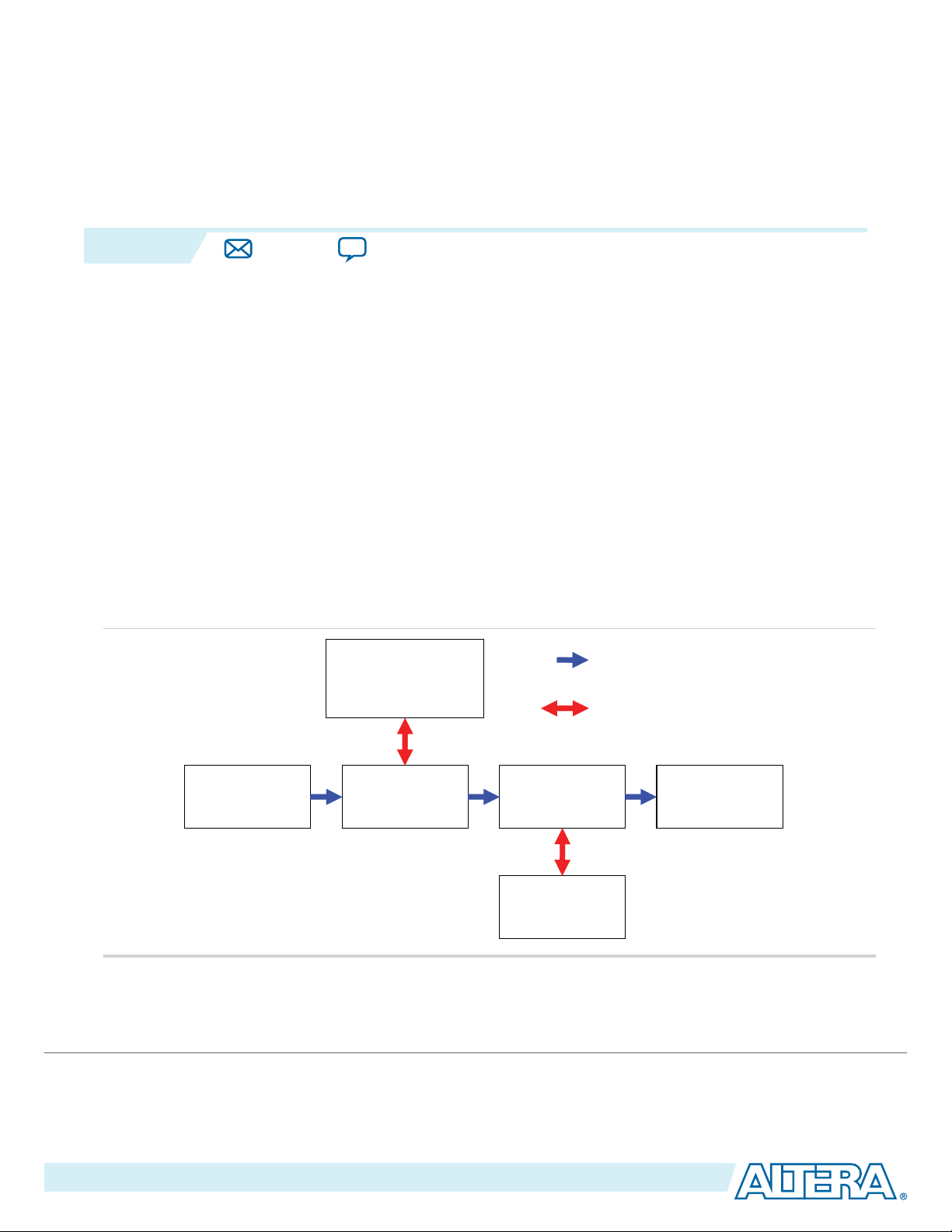
Figure 2-1: Abstracted Block Diagram Showing Avalon-ST and Avalon-MM Connections
The figure below shows an example of video processing data paths using the Avalon-ST and Avalon-MM
interfaces.
Note:
©
2015 Altera Corporation. All rights reserved. ALTERA, ARRIA, CYCLONE, ENPIRION, MAX, MEGACORE, NIOS, QUARTUS and STRATIX words and logos are
trademarks of Altera Corporation and registered in the U.S. Patent and Trademark Office and in other countries. All other words and logos identified as
trademarks or service marks are the property of their respective holders as described at www.altera.com/common/legal.html. Altera warrants performance
of its semiconductor products to current specifications in accordance with Altera's standard warranty, but reserves the right to make changes to any
products and services at any time without notice. Altera assumes no responsibility or liability arising out of the application or use of any information,
product, or service described herein except as expressly agreed to in writing by Altera. Altera customers are advised to obtain the latest version of device
specifications before relying on any published information and before placing orders for products or services.
This abstracted view is similar to that provided in the Qsys tool, where interface wires are grouped
together as single connections.
ISO
9001:2008
Registered
Page 29

2-2
Video Formats
The Clocked Video Input and Clocked Video Output IP cores also have external interfaces that support
clocked video standards. These IP cores can connect between the function’s Avalon-ST interfaces and
functions using clocked video standards such as BT.656.
Related Information
Avalon Interface Specifications
Provides more information about these interface types.
Video Formats
The Clocked Video Output IP cores create clocked video formats, and Clocked Video Input IP cores
accept clocked video formats.
The IP cores create and accept the following formats:
• Video with synchronization information embedded in the data (in BT656 or BT1120 format)
• Video with separate synchronization (H sync, V sync) signals
The CVO IP cores create a video frame consisting of horizontal and vertical blanking (containing syncs)
and areas of active picture (taken from the Avalon-ST Video input).
• Video with synchronization information embedded in the data (in BT656 or BT1120 format)
• Video with separate synchronization (H sync, V sync) signals
UG-VIPSUITE
2015.05.04
Altera Corporation
Interfaces
Send Feedback
Page 30
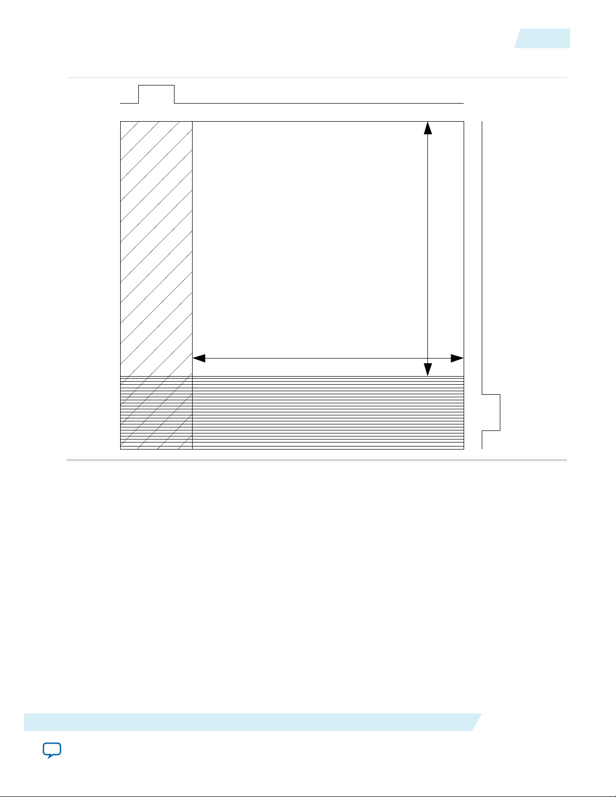
Vertical Blanking
F0 Active Picture
Horizontal Blanking
Horizontal Sync
Vertical Sync
Width
Height
UG-VIPSUITE
2015.05.04
Figure 2-2: Progressive Frame Format
Video Formats
2-3
Interfaces
Altera Corporation
Send Feedback
Page 31

Vertical Blanking
F0 Active Picture
Horizontal Blanking
Horizontal Sync
Vertical Sync
F0 Vertical Blanking
F1 Active Picture
Width
Height
Width
Height
Field
3FF XYZ00
TRS (10bit)
2-4
Video Formats
Figure 2-3: Interlaced Frame Format
UG-VIPSUITE
2015.05.04
For CVI and CVO IP cores, the BT656 and BT1120 formats use time reference signal (TRS) codes in the
video data to mark the places where synchronization information is inserted in the data.
Figure 2-4: Time Reference Signal Format
The TRS codes are made up of values that are not present in the video portion of the data, and they take
the format shown in the figure below.
Altera Corporation
Interfaces
Send Feedback
Page 32

D0 D1vid_data
vid_datavalid
UG-VIPSUITE
2015.05.04
Clocked Video Output IP Cores
For the embedded synchronization format, the CVO IP cores insert the horizontal and vertical syncs and
field into the data stream during the horizontal blanking period.
The IP cores create a sample for each clock cycle on the vid_data bus.
There are two extra signals only used when connecting to the SDI IP core. They are vid_trs, which is
high during the 3FF sample of the TRS, and vid_ln, which produces the current SDI line number. These
are used by the SDI IP core to insert line numbers and cyclical redundancy checks (CRC) into the SDI
stream as specified in the 1.5 Gbps HD SDI and 3 Gbps SDI standards.
The CVO IP cores insert any ancillary packets (packets with a type of 13 or 0xD) into the output video
during the vertical blanking. The IP cores begin inserting the packets on the lines specified in its
parameters or mode registers (ModeN Ancillary Line and ModeN F0 Ancillary Line). The CVO IP
cores stop inserting the packets at the end of the vertical blanking.
Clocked Video Input IP Cores
The CVI IP cores support both 8 and 10-bit TRS and XYZ words. When in 10-bit mode, the IP cores
ignore the bottom 2 bits of the TRS and XYZ words to allow easy transition from an 8-bit system.
Table 2-1: XYZ Word Format
The XYZ word contains the synchronization information and the relevant bits of its format.
Bits 10-bit 8-bit Description
Video Formats
2-5
Unused
[5:0] [3:0] These bits are not inspected by the CVI IP cores.
H (sync)
V (sync)
F (field)
Unused
For the embedded synchronization format, the vid_datavalid signal indicates a valid BT656 or BT1120
sample. The CVI IP cores only read the vid_data signal when vid_datavalid is 1.
Figure 2-5: Vid_datavalid Timing
6 4 When 1, the video is in a horizontal blanking period.
7 5 When 1, the video is in a vertical blanking period.
8 6 When 1, the video is interlaced and in field 1. When 0,
the video is either progressive or interlaced and in field
0.
9 7 These bits are not inspected by the CVI IP cores.
Interfaces
Send Feedback
Altera Corporation
Page 33

2-6
Video Formats
The CVI IP cores extract any ancillary packets from the Y channel during the vertical blanking. Ancillary
packets are not extracted from the horizontal blanking.
• Clocked Video Input IP core—The extracted packets are produced through the CVI IP cores’ AvalonST output with a packet type of 13 (0xD).
• Clocked Video Input II IP core— The extracted packets are stored in a RAM in the IP core, which can
be read via the control interface.
The extracted packets are produced through the CVI IP cores’ Avalon-ST output with a packet type of 13
(0xD).
For information about Avalon-ST Video ancillary data packets, refer to Ancillary Data Packets on page
2-19.
Separate Synchronization Format
The separate synchronization format uses separate signals to indicate the blanking, sync, and field
information.
The CVO IP cores create horizontal and vertical syncs and field information through their own signals.
The CVO IP cores create a sample for each clock cycle on the vid_data bus. The vid_datavalid signal
indicates when the vid_data video output is in an active picture period of the frame.
Table 2-2: Clocked Video Input and Output Signals for Separate Synchronization Format Video
UG-VIPSUITE
2015.05.04
Signal Name Description
vid_h_sync When 1, the video is in a horizontal synchronization period.
vid_v_sync When 1, the video is in a vertical synchronization period.
vid_f When 1, the video is interlaced and in field 1. When 0, the video is
either progressive or interlaced and in field 0.
vid_h When 1, the video is in a horizontal blanking period, (only for Clocked
Video Output IP core).
vid_v When 1, the video is in a vertical blanking period, (only for Clocked
Video Output IP core).
vid_de When asserted, the video is in an active picture period (not horizontal
or vertical blanking).
Note: Only for Clocked Video Input IP cores.
vid_datavalid When asserted, the video is in an active picture period (not horizontal
or vertical blanking).
Note: Only for Clocked Video Output IP cores.
Altera Corporation
Interfaces
Send Feedback
Page 34

vid_de/vid_datavalid (1)
D0 DNvid_data
(1): vid_datavalid: Clocked Video Output IP core
vid_de: Clocked Video Input IP core
D1 Dn+2Dn+1
vid_v_sync
vid_h_sync
vid_f
UG-VIPSUITE
2015.05.04
Avalon-ST Video Protocol
Figure 2-6: Separate Synchronization Signals Timing Diagram
The CVI IP cores only read the vid_data, vid_de, vid_h_sync, vid_v_sync, and vid_f signals when
vid_datavalid is 1. This allows the CVI IP cores to support oversampling where the video clock is
running at a higher rate than the pixel clock.
2-7
Video Locked Signal
The vid_locked signal indicates that the clocked video stream is active. When the signal has a value of 1,
the CVI IP cores take the input clocked video signals as valid, and read and process them as normal.
When the signal has a value of 0 (if for example the video cable is disconnected or the video interface is
not receiving a signal):
• Clocked Video Input IP core: The IP core takes the input clocked video signals as invalid and do not
process them.
• Clocked Video Input II IP core: The vid_clk domain registers of the IP core are held in reset and no
video is processed. The control and Avalon-ST Video interfaces are not held in reset and will respond
as normal. The vid_locked signal is synchronized internally to the IP core and is asynchronous to the
vid_clk.
If the vid_locked signal goes invalid while a frame of video is being processed, the CVI IP cores end the
frame of video early.
Avalon-ST Video Protocol
The Avalon-ST Video protocol is a packet-oriented way to send video and control data over Avalon-ST
connections. The IP cores in the Video and Image Processing Suite use the Avalon-ST Video protocol.
Using the Avalon-ST Video protocol allows the construction of image processing data paths which
automatically configure to changes in the format of the video being processed. This minimizes the
external control logic required to configure a video system.
Interfaces
Send Feedback
Altera Corporation
Page 35

2-8
Avalon-ST Video Protocol
Table 2-3: Avalon-ST Video Protocol Parameters
UG-VIPSUITE
2015.05.04
Parameter Values
IP Cores Frame Width/
Height
2D FIR Filter User-defined—
through
parameter editor
Alpha Blending Mixer Run-time
controlled
Mixer II No run-time
control
Chroma Resampler Run-time
controlled
Interlaced/
Progressive
Bits per Color
Sample
Progressive User-defined—
through
parameter editor
Progressive User-defined—
through
parameter editor
Specified
separately for
image data and
alpha blending.
Progressive User-defined—
through
parameter editor
Progressive User-defined—
through
parameter editor
Color Pattern
One, two, or three
channels in sequence.
• din and dout: One,
two or three
channels in
sequence
• alpha_in: A single
color plane
representing the
alpha value for each
pixel
Two or three channels
in parallel.
User-defined—through
parameter editor
Clipper/Clipper II Run-time
controlled
Color Plane Sequencer Run-time
controlled
Color Space Converter Run-time
controlled
Color Space ConverterIINo run-time
control
Control Synchronizer Run-time
controlled
Either one—
interlaced inputs
are accepted but
User-defined—
through
parameter editor
treated as
progressive
inputs.
Either one User-defined—
through
parameter editor
Either one User-defined—
through
parameter editor
Either one User-defined—
through
parameter editor
Run-time
controlled
User-defined—
through
parameter editor
Any combination of
one, two, three, or four
channels in each of
sequence or parallel.
User-defined—through
parameter editor
Three color planes in
parallel or sequence
Three color planes in
parallel or sequence
Up to four color planes
in parallel, with any
number of color planes
in sequence.
Altera Corporation
Interfaces
Send Feedback
Page 36

UG-VIPSUITE
2015.05.04
Parameter Values
Avalon-ST Video Protocol
2-9
IP Cores Frame Width/
Height
Deinterlacer Run-time
controlled
Deinterlacer II Run-time
controlled
Broadcast Deinterlacer Run-time
controlled
Interlaced/
Progressive
Interlaced input
and progressive
output (plus
optional
passthrough
mode for
progressive
input)
Interlaced input
and progressive
output (plus
passthrough
mode for
progressive
input)
Interlaced input
and progressive
output (plus
passthrough
mode for
progressive
input)
Bits per Color
Sample
User-defined—
through
parameter editor
User-defined—
through
parameter editor
User-defined—
through
parameter editor
Color Pattern
• One, two, or three
channels in
sequence
• alpha_in: A single
color plane
representing the
alpha value for each
pixel
Any combination of
two or three channels
in each of parallel.
Two channels in
parallel (4:2:2 only)
Interfaces
Frame Reader User-defined—
through AvalonMM slave
control port
Frame Buffer Run-time
controlled
Frame Buffer II No run-time
control
Gamma Corrector Run-time
controlled
User-defined—
through AvalonMM slave
User-defined—
through
parameter editor
control port
Progressive; in
some cases
interlaced data
User-defined—
through
parameter editor
accepted
Progressive
inputs only
User-defined—
through
parameter editor
Either one User-defined—
through
parameter editor
Up to four color planes
in parallel, with up to
three color planes in
sequence.
Any combination of
one, two, three, or four
channels in each of
sequence or parallel.
Any combination of
one, two, three, or four
channels in each of
parallel.
One, two or three
channels in sequence
or parallel.
Altera Corporation
Send Feedback
Page 37

2-10
Avalon-ST Video Protocol
UG-VIPSUITE
2015.05.04
Parameter Values
IP Cores Frame Width/
Height
Interlacer Run-time
controlled
Test Pattern Generator User-defined—
through
parameter editor
or run-time
controlled
Test Pattern GeneratorIIUser-defined—
through
parameter editor
or run-time
controlled
Packets
Interlaced/
Progressive
Progressive;
interlaced data is
either discarded
or propagated
without change
in parameter
editor
User-defined—
through
parameter editor
User-defined—
through
parameter editor
Bits per Color
Sample
User-defined—
through
parameter editor
User-defined—
through
parameter editor
User-defined—
through
parameter editor
Color Pattern
One, two or three
channels in sequence
or parallel.
One, two or three
channels in sequence
or parallel.
RGB 4:4:4 or YCbCr
4:4:4, 4:2:2 or 4:2:0 in
parallel or sequence.
The packets of the Avalon-ST Video protocol are split into symbols—each symbol represents a single
piece of data. For all packet types on a particular Avalon-ST interface, the number of symbols sent in
parallel (that is, on one clock cycle) and the bit width of all symbols is fixed. The symbol bit width and
number of symbols sent in parallel defines the structure of the packets.
The functions predefine the following three types of packet:
• Video data packets containing only uncompressed video data
• Control data packets containing the control data configure the cores for incoming video data packets
• Ancillary (non-video) data packets containing ancillary packets from the vertical blanking period of a
video frame
Another seven packet types are reserved for users, and five packet types reserved for future definition by
Altera.
The packet type is defined by a 4-bit packet type identifier. This type identifier is the first value of any
packet. It is the symbol in the least significant bits of the interface. Functions do not use any symbols in
parallel with the type identifier.
Table 2-4: Avalon-ST Video Packet Types
Type Identifier Description
0 Video data packet
1–8 User packet types
9–12 Reserved for future Altera use
Altera Corporation
Interfaces
Send Feedback
Page 38

Start
End
Packet type identifier
(4 bits in least significant symbol,
X’s for unused symbols)
Data of the packet
(Split into symbols)
X
Symbols can be
transmitted in parallel
(2 in this example)
UG-VIPSUITE
2015.05.04
Type Identifier Description
13 Ancillary data packet
14 Reserved for future Altera use
15 Control data packet
Figure 2-7: Packet Structure
Video Data Packets
2-11
The Avalon-ST Video protocol is designed to be most efficient for transferring video data, therefore the
symbol bit width and the number of symbols transferred in parallel (that is, in one clock cycle) are defined
by the parameters of the video data packet types.
Video Data Packets
Video data packets transmit video data between the IP cores.
A video data packet contains the color plane values of the pixels for an entire progressive frame or an
entire interlaced field.
The IP core sends the video data per pixel in a raster scan order. The pixel order is as follows:
1. From the top left of the image right wards along the horizontal line.
2. At the end of the current line, jump to the left most pixel of the next horizontal line down.
3. Go rightwards along the horizontal line.
4. Repeat steps 2 and 3 until the bottom right pixel is reached and the frame has been sent.
Static Parameters of Video Data Packets
Two static parameters specify the Avalon-ST interface that video systems use—bits per pixel per color
plane and color pattern.
Bits Per Pixel Per Color Plane
The maximum number of bits that represent each color plane value within each pixel. For example,
R’G’B’ data of eight bits per sample (24 bits per pixel) would use eight bits per pixel per color plane.
Interfaces
Send Feedback
Note:
This parameter also defines the bit width of symbols for all packet types on a particular Avalon-ST
interface. An Avalon-ST interface must be at least four bits wide to fully support the Avalon-ST
Video protocol.
Altera Corporation
Page 39

RGB
Symbol transmitted first
Symbol transmitted last
B
G
R
Symbol in most significant bits
Symbol in least significant bits
Cb Cr
Y Y
2-12
Static Parameters of Video Data Packets
Color Pattern
The organization of the color plane samples within a video data packet is referred to as the color pattern.
This parameter also defines the bit width of symbols for all packet types on a particular Avalon-ST
interface. An Avalon-ST interface must be at least four bits wide to fully support the Avalon-ST Video
protocol.
A color pattern is represented as a matrix which defines a repeating pattern of color plane samples that
make up a pixel (or multiple pixels). The height of the matrix indicates the number of color plane samples
transmitted in parallel, the width determines how many cycles of data are transmitted before the pattern
repeats.
Each color plane sample in the color pattern maps to an Avalon-ST symbol. The mapping is such that
color plane samples on the left of the color pattern matrix are the symbols transmitted first. Color plane
samples on the top are assigned to the symbols occupying the most significant bits of the Avalon-ST data
signal.
Figure 2-8: Symbol Transmission Order
UG-VIPSUITE
2015.05.04
Note:
The number of color plane samples transmitted in parallel (that is, in one clock cycle) defines the
number of symbols transmitted in parallel for all packet types on a particular Avalon-ST interface.
A color pattern can represent more than one pixel. This is the case when consecutive pixels contain
samples from different color planes. There must always be at least one common color plane between all
pixels in the same color pattern. Color patterns representing more than one pixel are identifiable by a
repeated color plane name. The number of times a color plane name is repeated is the number of pixels
represented.
Figure 2-9: Horizontally Subsampled Y'CbCr
The figure below shows two pixels of horizontally subsampled Y'CbCr (4:2:2) where Cb and Cr alternate
between consecutive pixels.
In the common case, each element of the matrix contains the name of a color plane from which a sample
must be taken. The exception is for vertically sub sampled color planes. These are indicated by writing the
names of two color planes in a single element, one above the other.
Altera Corporation
Interfaces
Send Feedback
Page 40

Cb
Cr
Y Y
Plane for even rows
Plane for odd rows
RGB
B
G
R
Cb Cr
Y Y
B
G
R
RGB
UG-VIPSUITE
2015.05.04
Static Parameters of Video Data Packets
Figure 2-10: Vertically Subsampled Y'CbCr
The figure below samples from the upper color plane transmitted on even rows and samples from the
lower plane transmitted on odd rows.
Table 2-5: Examples of Static Avalon-ST Video Data Packet Parameters
The table below lists the static parameters and gives some examples of how you can use them.
Parameter Description
Bits per Color Sample Color Pattern
2-13
8
Three color planes, B’, G’, and R’ are transmitted in
alternating sequence and each B’, G’, or R’ sample is
represented using 8 bits of data.
10
Three color planes are transmitted in parallel, leading to
higher throughput than when transmitted in sequence,
usually at higher cost. Each R’, G’, or B’ sample is
represented using 10 bits of data, so that, in total, 30 bits
of data are transmitted in parallel.
10
4:2:2 video in the Y’CbCr color space, where there are
twice as many Y’ samples as Cb or Cr samples. One Y’
sample and one of either a Cb or a Cr sample is
transmitted in parallel. Each sample is represented using
10 bits of data.
The Avalon-ST Video protocol does not force the use of specific color patterns, however a few IP cores of
the Video and Image Processing Suite only process video data packets correctly if they use a certain set of
color patterns.
Table 2-6: Recommended Color Patterns
The table below lists the recommended color patterns for common combinations of color spaces and color planes
in parallel and sequence.
Parameter Recommended Color Patterns
Interfaces
Bits per Color Sample Parallel Sequence
R’G’B
Send Feedback
Altera Corporation
Page 41

Y
Cb
Cr
CrCb Y
Cb Cr
Y Y
CrCb YY
2-14
Static Parameters of Video Data Packets
Parameter Recommended Color Patterns
Bits per Color Sample Parallel Sequence
Y’CbCr
4:2:2 Y’CbCr
Following these recommendations, ensures compatibility minimizing the need for color pattern
rearranging. These color patterns are designed to be compatible with common clocked video standards
where possible.
Note:
If you must rearrange color patterns, use the Color Plane Sequencer IP core.
4:2:2 Mode Support
UG-VIPSUITE
2015.05.04
Some of the IP cores in the Video and Image Processing Suite do not support 4:2:2 mode. You can
parameterize the IP cores to 2 symbols in parallel or sequence to make them appear like 4:2:2.
The following IP cores do not support 4:2:2 mode:
• 2D FIR Filter
• Color Space Converter
Some IP cores use 2-pixel alignment of 4:2:2. These IP cores send pixels in “pairs” to get a complete “Y,
Cb and Cr”. The following IP cores use 2-pixel alignment:
• Alpha Blending Mixer
• Clipper
• Clipper II
• Gamma Corrector
Specifying Color Pattern Options
You can specify parameters in the parameter editor that allow you to describe a color pattern that has its
color planes entirely in sequence (one per cycle) or entirely in parallel (all in one cycle). You can select the
number of color planes per pixel, and whether the planes of the color pattern transmit in sequence or in
parallel.
Some of the IP cores' user interfaces provide controls allowing you to describe a color pattern that has
color plane samples in parallel with each other and in sequence such that it extends over multiple clock
cycles. You can select the number of color planes of the color pattern in parallel (number of rows of the
color pattern) and the number of color planes in sequence (number of columns of the color pattern).
Altera Corporation
Interfaces
Send Feedback
Page 42

Start End
Video data packet type identifier
(4 bits in least significant symbol,
X’s for unused symbols)
Video Data, repeating a
regular color pattern
Color
Pattern
Bits per pixel
per color plane
= 8
0
X
X
Symbols on bits 23:16
Symbols on bits 15:8
Symbols on bits 7:0
B
G
R
B
G
R
B
G
R
B
G
R
B
G
R
B
G
R
B
G
R
B
G
R
B
G
R
B
G
R
B
G
R
0
Symbols on bits 7:0
B G
R
Color
Pattern
Bits per pixel
per color plane
= 8
Video Data, repeating a
regular color pattern
Video data packet type identifier
(4 bits in least significant symbol,
X’s for unused symbols)
Start End
B G
R
B G
R
B G
R
B G
R
UG-VIPSUITE
2015.05.04
Control Data Packets
Structure of Video Data Packets
Figure 2-11: Parallel Color Pattern
This figure shows the structure of a video data packet using a set parallel color pattern and bits per pixel
per color plane.
2-15
Control Data Packets
Interfaces
Figure 2-12: Sequence Color Pattern
This figure shows the structure of a video data packet using a set sequential color pattern and bits per
pixel per color plane.
Only aligned pixels supported of frame/line size modular pixels in parallel.
Note:
Control data packets configure the IP cores so that they correctly process the video data packets that
follow.
In addition to a packet type identifier of value 15, control data packets contain these data:
• Width (16 bit)
• Height (16 bit)
• Interlacing (4 bit)
Altera Corporation
Send Feedback
Page 43

2-16
Control Data Packets
UG-VIPSUITE
2015.05.04
The width and height values are the dimensions of the video data packets that follow. The width refers to
the width in pixels of the lines of a frame. The height refers to the number of lines in a frame or field. For
example, a field of interlaced 1920×1080 (1080i) would have a width of 1920 and a height of 540, and a
frame of 1920×1080 (1080p) would have a width of 1920 and a height of 1080.
When a video data packet uses a subsampled color pattern, the individual color planes of the video data
packet have different dimensions. For example:
• 4:2:2 has one full width, full height plane and two half width, full height planes
• 4:2:0 has one full width, full height plane and two half width, half height planes
In these cases, you must configure the width and height fields of the control data packet for the fully
sampled, full width, and full height plane.
The interlacing value in the control packet indicates whether the video data packets that follow contain
progressing or interlaced video. The most significant two bits of the interlacing nibble describe whether
the next video data packet is either progressive, interlaced field 0 (F0) containing lines 0, 2, 4.... or
interlaced field 1 (F1) containing lines 1, 3, 5... 00 means progressive, 10 means interlaced F0, and 11
means interlaced F1.
The meaning of the second two bits is dependent on the first two bits. If the first two bits are set to 10 (F0)
or 11 (F1), the second two bits describe the synchronization of interlaced data. Use the synchronization
bits for progressive segmented frame (PsF) content, where progressive frames are transmitted as two
interlaced fields.
Synchronizing on F0 means that a video frame should be constructed from an F1 followed by an F0.
Similarly, synchronizing on F1 means that a video frame should be constructed from an F0 followed by an
F1. The other synchronization options are don't care when there is no difference in combining an F1 then
F0, or an F0 then F1. The final option is don't know to indicate that the synchronization of the interlaced
fields is unknown. The encoding for these options are 00 for synchronize on F0, 01 for synchronize on F1,
11 for don't care, and 10 for don't know.
Note:
The synchronization bits do not affect the behavior of the Deinterlacing IP cores because the
synchronization field is fixed at compile time. However, they do affect the behavior of the Frame
Buffer IP core when dropping and repeating pairs of fields.
If the first two bits indicate a progressive frame, the second two bits indicate the type of the last field that
the progressive frame was deinterlaced from. The encoding for this is 10 for unknown or 11 for not
deinterlaced, 00 for F0 last, and 01 for F1 last.
Table 2-7: Examples of Control Data Packet Parameters
Parameters
Type Width Height Interlacin
g
15 1920 1080 0011 The frames that follow are progressive with a
resolution of 1920×1080.
Description
15 640 480 0011 The frames that follow are progressive with a
Altera Corporation
resolution of 640×480.
Interfaces
Send Feedback
Page 44

UG-VIPSUITE
2015.05.04
Control Data Packets
Parameters
Type Width Height Interlacin
g
Description
15 640 480 0000 The frames that follow are progressive with a
resolution of 640×480. The frames were deinterlaced
using F0 as the last field.
15 640 480 0001 The frames that follow are progressive with a
resolution of 640×480. The frames were deinterlaced
using F1 as the last field.
15 640 240 1000 The fields that follow are 640 pixels wide and 240
pixels high. The next field is F0 (even lines) and it is
paired with the F1 field that precedes it.
15 1920 540 1100 The fields that follow are 1920 pixels wide and 540
pixels high. The next field is F1 (odd lines) and it is
paired with the F0 field that follows it.
15 1920 540 1101 The fields that follow are 1920 pixels wide and 540
pixels high. The next field is F1 (odd lines) and it is
paired with the F0 field that precedes it.
2-17
15 1920 540 1011 The fields that follow are 1920 pixels wide and 540
pixels high. The next field is F0 (even lines) and you
must handle the stream as genuine interlaced video
material where the fields are all temporally disjoint.
15 1920 540 1010 The fields that follow are 1920 pixels wide and 540
pixels high. The next field is F0 (even lines) and you
must handle the stream as genuine interlaced video
content although it may originate from a progressive
source converted with a pull-down.
Use of Control Data Packets
A control data packet must immediately precede every video data packet. To facilitate this, any IP
function that generates control data packets must do so once before each video data packet. Additionally
all other IP cores in the processing pipeline must either pass on a control data packet or generate a new
one before each video data packet. If the function receives more than one control data packet before a
video data packet, it uses the parameters from the last received control data packet. If the function receives
a video data packet with no preceding control data packet, the current functions keep the settings from
the last control data packet received, with the exception of the next interlaced field type—toggling
between F0 and F1 for each new video data packet that it receives.
This behavior may not be supported in future releases. Altera recommends for forward compati‐
Note:
bility that functions implementing the protocol ensure there is a control data packet immediately
preceding each video data packet.
Interfaces
Altera Corporation
Send Feedback
Page 45

Start End
3
15
Symbols in least significant bits
Symbols in middle significant bits
Symbols in most significant bits
Control data, reference numbers to Table 4-5
X
Control data packet type identifier
(4 bits in least significant symbol,
X’s for unused symbols)
X
96
852
741
Control data packet type identifier
(4 bits in least significant symbol,
X’s for unused symbols)
Symbols in least significant bits
Symbols in most significant bits
Start End
Control data, reference numbers to Table 4-5
3
15
XX
9
6 8
527
4
1
2-18
Control Data Packets
Structure of a Control Data Packet
A control data packet complies with the standard of a packet type identifier followed by a data payload.
The data payload is split into nibbles of 4 bits; each data nibble is part of a symbol. If the width of a
symbol is greater than 4 bits, the function does not use the most significant bits of the symbol.
Order Symbol Order Symbol
1 width[15..12] 6 height[11..8]
2 width[11..8] 7 height[7..4]
3 width[7..4] 8 height[3..0]
4 width[3..0] 9 interlacing[3..0]
5 height[15..12] — —
If the number of symbols transmitted in one cycle of the Avalon-ST interface is more than one, then the
nibbles are distributed such that the symbols occupying the least significant bits are populated first.
The following figures show examples of control data packets, and how they are split into symbols.
Figure 2-13: Three Symbols in Parallel
UG-VIPSUITE
2015.05.04
Figure 2-14: Two Symbols in Parallel
Altera Corporation
Interfaces
Send Feedback
Page 46

Control data, reference numbers to Table 4-5
Control data packet type identifier
(4 bits in least significant symbol,
X’s for unused symbols)
Start End
315 96 852 741
UG-VIPSUITE
2015.05.04
Figure 2-15: One Symbol in Parallel
Ancillary Data Packets
Ancillary data packets send ancillary packets between IP cores.
Ancillary data packets are typically placed between a control data packet and a video data packet and
contain information that describes the video data packet, for example active format description codes.
An ancillary data packet can contain one or more ancillary packets; each ancillary packet starts with the
hexadecimal code 0, 3FF, 3FF.
Ancillary Data Packets
2-19
Note: The format of ancillary packets is defined in the SMPTE S291M standard.
IP cores are not required to understand or process ancillary data packets, but must forward them on, as is
done with user-defined and Altera-reserved packets.
User-Defined and Altera-Reserved Packets
The Avalon-ST Video protocol specifies seven packet types reserved for use by users and five packet types
reserved for future use by Altera.
The data content of all of these packets is undefined. However the structure must follow the rule that the
packets are split into symbols as defined by the number color plane samples sent in one cycle of the color
pattern.
Unlike control data packets, user packets are not restricted to four bits of data per symbol. However when
a core reduces the bits per pixel per color plane (and thus the bit width of the symbols) to less than the
number of bits in use per symbol, data is lost.
Packet Propagation
The Avalon-ST Video protocol is optimized for the transfer of video data while still providing a flexible
way to transfer control data and other information.
Interfaces
Send Feedback
Altera Corporation
Page 47

2-20
Transmission of Avalon-ST Video Over Avalon-ST Interfaces
To make the protocol flexible and extensible, the Video and Image Processing IP cores obey the following
rules about propagating non-video packets:
• The IP cores must propagate user packets until they receive an end of packet signal. Nevertheless, the
IP cores that buffer packets into external memory may introduce a maximum size due to limited
storage space.
• The IP cores can propagate control packets or modify them on the fly. The IP cores can also cancel a
control packet by following it with a new control packet.
• When the bits per color sample change from the input to the output side of an IP core, the non-video
packets are truncated or padded. Otherwise, the full bit width is transferred.
• The IP cores that can change the color pattern of a video data packet may also pad non-video data
packets with extra data. When defining a packet type where the length is variable and meaningful, it is
recommended to send the length at the start of the packet.
Transmission of Avalon-ST Video Over Avalon-ST Interfaces
Avalon-ST Video is a protocol transmitted over Avalon-ST interfaces.
Table 2-8: Avalon-ST Interface Parameters
The table below lists the values of these parameters that are defined for transmission of the Avalon-ST Video
protocol. All parameters not explicitly listed in the table have undefined values.
Parameter Name Value
UG-VIPSUITE
2015.05.04
BITS_PER_SYMBOL Variable. Always equal to the Bits per Color Sample parameter value of
the stream of pixel data being transferred.
PIXELS_IN_PARALLEL Variable. Always equal to the number of pixels transferred in parallel.
Note: Only aligned pixels supported of frame/line size module
pixels in parallel.
SYMBOLS_PER_BEAT Variable. Always equal to the number of color samples being
transferred in parallel. This is equivalent to the number of rows in the
color pattern parameter value of the stream of pixel data being
transferred.
READY_LATENCY 1
Table 2-9: Avalon-ST Interface Signal Types
The table below lists the signals for transmitting Avalon-ST Video. The unused signals are not listed.
Signal Width Direction
ready 1 Sink to Source
valid 1 Source to Sink
data bits_per_symbol × symbols_per_beat ×
Source to Sink
pixels_in_parallel
empty 1–8 Source to Sink
startofpacket 1 Source to Sink
Altera Corporation
Interfaces
Send Feedback
Page 48

B
G
R
UG-VIPSUITE
2015.05.04
Signal Width Direction
endofpacket 1 Source to Sink
Related Information
Avalon Interface Specifications
Provides more information about these interface types.
Packet Transfer Examples
All packets are transferred using the Avalon-ST signals in the same way.
Example 1 (Data Transferred in Parallel)
This example shows the transfer of a video data packet in to and then out of a generic IP core that
supports the Avalon-ST Video protocol.
In this case, both the input and output video data packets have a parallel color pattern and eight bits per
pixel per color plane.
Table 2-10: Parameters for Example of Data Transferred in Parallel
Parameter Value
Packet Transfer Examples
2-21
Bits per Pixel per Color Plane 8
Color Pattern
Interfaces
Altera Corporation
Send Feedback
Page 49

clock
din_ready
din_startofpacket
din_valid
din_data
23:16
15:8
7:0
dout_ready
dout_valid
dout_endofpacket
dout_data
23:16
15:8
7:0
1.
2.
3.
4. 5. 6. 7.
B
0,0
G
0,0
R
0,0
B
1,0
B
2,0
G
2,0
R
1,0
B
2,0
G
1,0
B
0,0
G
0,0
R
0,0
B
x,y
G
x,y
R
x,y
n.
X
X
0
din_endofpacket
dout_startofpacket
X
X
0
2-22
Packet Transfer Examples
Figure 2-16: Timing Diagram Showing R’G’B’ Transferred in Parallel
The figure below shows how the first few pixels of a frame are processed.
UG-VIPSUITE
2015.05.04
Altera Corporation
This example has one Avalon-ST port named din and one Avalon-ST port named dout. Data flows into
the IP core through din, is processed and flows out of the IP core through dout.
There are five signals types—ready, valid, data, startofpacket, and endofpacket—associated with each port.
The din_ready signal is an output from the IP core and indicates when the input port is ready to receive
data. The din_valid and din_data signals are both inputs. The source connected to the input port sets
din_valid to logic '1' when din_data has useful information that must be sampled. The din_startofpacket signal is an input that is raised to indicate the start of a packet, with din_endofpacket signaling
the end of a packet. The five output port signals have equivalent but opposite semantics.
The sequence of events for this example:
1. Initially, din_ready is logic '0', indicating that the IP core is not ready to receive data on the next cycle.
Many of the Video and Image Processing Suite IP cores are not ready for a few clock cycles in between
rows of image data or in between video frames.
2. The IP core sets din_ready to logic '1', indicating that the input port is ready to receive data one clock
cycle later. The number of clock cycles of delay which must be applied to a ready signal is referred to as
Interfaces
Send Feedback
Page 50

RGB
UG-VIPSUITE
2015.05.04
Packet Transfer Examples
ready latency in the Avalon Interface Specifications. All the Avalon-ST interfaces used by the Video
and Image Processing Suite IP cores have a ready latency of one clock cycle.
3. The source feeding the input port sets din_valid to logic '1' indicating that it is sending data on the
data port and sets din_startofpacket to logic '1' indicating that the data is the first value of a new
packet. The data is 0, indicating that the packet is video data.
4. The source feeding the input port holds din_valid at logic '1' and drops din_startofpacket
indicating that it is now sending the body of the packet. It puts all three color values of the top left pixel
of the frame on to din_data.
5. No data is transmitted for a cycle even though din_ready was logic '1' during the previous clock cycle
and therefore the input port is still asserting that it is ready for data. This could be because the source
has no data to transfer. For example, if the source is a FIFO, it may have become empty.
6. Data transmission resumes on the input port: din_valid transitions to logic '1' and the second pixel is
transferred on din_data. Simultaneously, the IP core begins transferring data on the output port. The
example IP core has an internal latency of three clock cycles so the first output is transferred three
cycles after being received. This output is the type identifier for a video packet being passed along the
datapath.
7. The third pixel is input and the first processed pixel is output.
8. For the final sample of a frame, the source sets din_endofpacket to logic '1', din_valid to '1', and puts
the bottom-right pixel of the frame on to din_data.
Example 2 (Data Transferred in Sequence)
2-23
This example shows how a number of pixels from the middle of a frame could be processed by another IP
core. This time handling a color pattern that has planes B'G'R' in sequence. This example does not show
the start of packet and end of packet signals because these signals are always low during the middle of a
packet.
Table 2-11: Parameters for Example of Data Transferred in Sequence
The table below lists the bits per pixel per color plane and color pattern.
Parameter Value
Bits per Color Sample 8
Color Pattern
Interfaces
Altera Corporation
Send Feedback
Page 51

clock
din_ready
din_valid
din_data 7:0
R
m,n
R
G
0,0Gm,n
B
m,n
B
m+1,n
1.
2.
3.
4.
5. 6.
7.
dout_ready
dout_valid
dout_data 7:0
R
8.
9.
G
1,0
G
m+1,n
G
0,0
G
m,n
B
m,n
m+1,n
m,n
2-24
Packet Transfer Examples
Figure 2-17: Timing Diagram Showing R’G’B’ Transferred in Sequence
The figure shows how a number of pixels from the middle of a frame are processed.
This example is similar to example one except that it is configured to accept data in sequence rather than
parallel. The signals shown in the timing diagram are therefore the same but with the exception that the
two data ports are only 8 bits wide.
UG-VIPSUITE
2015.05.04
The sequence of events for this example:
1. Initially, din_ready is logic '1'. The source driving the input port sets din_valid to logic '1' and puts
the blue color value B
2. The source holds din_valid at logic '1' and the green color value G
3. The corresponding red color value R
on the din_data port.
m,n
is input.
m,n
is input.
m,n
4. The IP core sets dout_valid to logic '1' and outputs the blue color value of the first processed color
sample on the dout_data port. Simultaneously the sink connected to the output port sets dout_ready
to logic '0'. The Avalon Interface Specifications state that sinks may set ready to logic '0' at any time, for
example because the sink is a FIFO and it has become full.
5. The IP core sets dout_valid to logic '0' and stops putting data on the dout_data port because the sink
is not ready for data. The IP core also sets din_ready to logic '0' because there is no way to output data
and the IP core must stop the source from sending more data before it uses all internal buffer space.
The sink holds din_valid at logic '1' and transmits one more color sample G
, which is legal
m+1,n
because the ready latency of the interface means that the change in the IP core's readiness does not take
effect for one clock cycle.
6. Both the input and output interfaces do not transfer any data: the IP core stalls to wait for the sink.
7. The sink sets dout_ready to logic '1'. This could be because space has been cleared in a FIFO.
8. The IP core sets dout_valid to logic '1' and resumes transmitting data. Now that the flow of data is
unimpeded again, it sets din_ready to logic '1'.
9. The source responds to din_ready by setting din_valid to logic '1' and resuming data transfer.
Altera Corporation
Interfaces
Send Feedback
Page 52

clock
din_valid
din_startofpacket
CbCr din_data(13:10)
0x2
din_endofpacket
Y din_data(3:0)
0x0 0x0 0x0
0x00x0 0xD0xF 0x0 0xF 10xx
720(0x02D0) 240(0x00F0) image dataif0
binary
f0 - 10xx
f1 - 11xx
p - 00xx
UG-VIPSUITE
2015.05.04
Avalon-MM Slave Interfaces
Example 3 (Control Data Transfer)
Figure 2-18: Timing Diagram Showing Control Packet Transfer
This figure shows the transfer of a control packet for a field of 720×480 video (with field height 240).
2-25
Avalon-MM Slave Interfaces
The packet is transferred over an interface configured for 10-bit data with two color planes in parallel.
Each word of the control packet is transferred in the lowest four bits of a color plane, starting with bits 3:0,
then 13:10.
The Video and Image Processing Suite IP cores that permit run-time control of some aspects of their
behavior, use a common type of Avalon-MM slave interface for this purpose.
Each slave interface provides access to a set of control registers which must be set by external hardware.
You must assume that these registers power up in an undefined state. The set of available control registers
and the width in binary bits of each register varies with each control interface.
Interfaces
Send Feedback
Altera Corporation
Page 53

2-26
Avalon-MM Slave Interfaces
UG-VIPSUITE
2015.05.04
The first two registers of every control interface perform the following two functions (the others vary with
each control interface):
• Register 0 is the Go register. Bit zero of this register is the Go bit. A few cycles after the function comes
out of reset, it writes a zero in the Go bit (remember that all registers in Avalon-MM control slaves
power up in an undefined state).
• Although there are a few exceptions, most Video and Image Processing Suite IP cores stop at the
beginning of an image data packet if the Go bit is set to 0. This allows you to stop the IP core and to
program run-time control data before the processing of the image data begins. A few cycles after the Go
bit is set by external logic connected to the control port, the IP core begins processing image data. If
the Go bit is unset while data is being processed, then the IP core stops processing data again at the
beginning of the next image data packet and waits until the Go bit is set by external logic.
• Register 1 is the Status register. Bit zero of this register is the Status bit; the function does not use all
other bits. The function sets the Status bit to 1 when it is running, and zero otherwise. External logic
attached to the control port must not attempt to write to the Status register.
The following pseudo-code illustrates the design of functions that double-buffer their control (that is, all
IP cores except the Gamma Corrector and some Scaler II parameterizations):
go = 0;
while (true)
{
read_non_image_data_packets();
status = 0;
while (go != 1)
wait;
read_control(); // Copies control to internal registers
status = 1;
send_image_data_header();
process_frame();
}
For IP cores that do not double buffer their control data, the algorithm described in the previous
paragraph is still largely applicable but the changes to the control register will affect the current frame.
Most Video and Image Processing Suite IP cores with a slave interface read and propagate non-image data
packets from the input stream until the image data header (0) of an image data packet has been received.
The status bit is then set to 0 and the IP core waits until the Go bit is set to 1 if it is not already. Once the
Go bit is set to 1, the IP core buffers control data, sets its status bit back to 1, and starts processing image
data.
Note:
There is a small amount of buffering at the input of each Video and Image Processing Suite IP core
and you must expect that a few samples are read and stored past the image data header even if the
function is stalled.
You can use the Go and Status registers in combination to synchronize changes in control data to the
start and end of frames. For example, suppose you want to build a system with a Gamma Corrector IP
core where the gamma look-up table is updated between each video frame.
Altera Corporation
Interfaces
Send Feedback
Page 54

UG-VIPSUITE
2015.05.04
Specification of the Type of Avalon-MM Slave Interfaces
2-27
You can build logic (or program a Nios II processor) to control the gamma corrector as follows:
1. Set the Go bit to zero. This causes the IP core to stop processing at the end of the current frame.
2. Poll the Status bit until the IP core sets it to zero. This occurs at the end of the current frame, after the
IP core has stopped processing data.
3. Update the gamma look-up table.
4. Set the Go bit to one. This causes the IP core to start processing the next frame.
5. Poll the Status bit until the IP core sets it to one. This occurs when the IP core has started processing
the next frame (and therefore setting the Go bit to zero causes it to stop processing at the end of the
next frame).
6. Repeat steps 1 to 5 until all frames are processed.
This procedure ensures that the update is performed exactly once per frame and that the IP core is not
processing data while the update is performed.
When using IP cores which double-buffer control data, such as the Alpha Blending Mixer, a more simple
process may be sufficient:
1. Set the Go bit to zero. This causes the IP core to stop if it gets to the end of a frame while the update is
in progress.
2. Update the control data.
3. Set the Go bit to one.
The next time a new frame is started after the Go bit is set to one, the new control data is loaded into the IP
core.
The reading on non-video packets is performed by handling any packet until one arrives with type 0. This
means that when the Go bit is checked, the non-video type has been taken out of the stream but the video
is retained.
Specification of the Type of Avalon-MM Slave Interfaces
The Avalon-MM slave interfaces only use certain signals for Video and Image Processing Suite IP cores.
Table 2-12: Avalon-MM Slave Interface Signal Types
The table below lists the signals that the Avalon-MM slave interfaces use in the Video and Image Processing Suite.
The unused signals are not listed.
The slave interfaces of the Video and Image Processing IP cores may use either chipselect or read.
Note:
Signal Width Direction
chipselect 1 Input
read 1 Input
address Variable Input
readdata Variable Output
(5)
Interfaces
write 1 Input
writedata
(5)
Variable Input
For slave interfaces that do not have a predefined number of wait cycles to service a read or a write request.
Altera Corporation
Send Feedback
Page 55

2-28
Avalon-MM Master Interfaces
Signal Width Direction
waitrequest 1 Output
(6)
irq
1 Output
Note: The list does not include clock and reset signal types. The Video and Image Processing Suite IP
cores do not support Avalon-MM interfaces in multiple clock domains. Instead, the Avalon-MM
slave interfaces must operate synchronously to the main clock and reset signals of the IP core. The
Avalon-MM slave interfaces must operate synchronously to this clock.
The control interfaces of the Video and Image Processing Suite IP cores that do not use a waitrequest
signal, exhibit the following transfer properties:
• Zero wait states on write operations
• Two wait states on read operation
Avalon-MM Master Interfaces
The Video and Image Processing Suite IP cores use a common type of Avalon-MM master interface for
access to external memory.
UG-VIPSUITE
2015.05.04
Connect these master interfaces to external memory resources through arbitration logic such as that
provided by the system interconnect fabric.
Specification of the Type of Avalon-MM Master Interfaces
The Avalon-MM master interfaces only use certain signals for Video and Image Processing Suite IP cores.
Table 2-13: Avalon-MM Master Interface Signal Types
The table below lists the signals that the Avalon-MM master interfaces use in the Video and Image Processing
Suite IP cores. The unused signals are not listed.
Signal Width Direction Usage
clock 1 Input Read-Write (optional)
readdata Variable Output Read-only
readdatavalid 1 Read-only
reset 1 Read-Write (optional)
waitrequest 1 Output Read-Write
address 32 Input Read-Write
burstcount Variable Read-Write
read 1 Input Read-only
write 1 Input Write-only
writedata Variable Input Write-only
(6)
For slave interfaces with an interrupt request line.
Altera Corporation
Interfaces
Send Feedback
Page 56

UG-VIPSUITE
2015.05.04
Buffering of Non-Image Data Packets in Memory
Note: The clock and reset signal types are optional. The Avalon-MM master interfaces can operate on a
different clock from the IP core and its other interfaces by selecting the relevant option in the
parameter editor when and if it is available.
A master interface that only performs write transactions do not require the read-only signals. A master
interface that only performs read transactions do not require the write-only signals. To simplify the
Avalon-MM master interfaces and improve efficiency, read-only ports are not present in write-only
masters, and write-only ports are not present in read-only masters. Read-write ports are present in all
Avalon-MM master interfaces.
The external memory access interfaces of the Video and Image Processing Suite IP cores have pipeline
with variable latency feature.
Related Information
Avalon Interface Specifications
Provides more information about these interface types.
Buffering of Non-Image Data Packets in Memory
The Frame Buffer and the Deinterlacing IP cores (when buffering is enabled) route the video stream
through an external memory. Non-image data packets must be buffered and delayed along with the frame
or field they relate to and extra memory space has to be allocated. You must specify the maximum
number of packets per field and the maximum size of each packet to cover this requirement.
2-29
The maximum size of a packet is given as a number of symbols, header included. For instance, the size of
an Avalon-ST Video control packet is 10. This size does not depend on the number of channels
transmitted in parallel. Packets larger than this maximum limit may be truncated as extra data is
discarded.
The maximum number of packets is the number of packets that can be stored with each field or frame.
Older packets are discarded first in case of overflow. When frame dropping is enabled, the packets
associated with a field that has been dropped are automatically transferred to the next field and count
towards this limit.
The Frame Buffer and the Deinterlacing IP cores handle Avalon-ST Video control packets differently. The
Frame Buffer processes and discards incoming control packets whereas the Deinterlacing IP cores process
and buffer incoming control packets in memory before propagating them. Because both IP cores generate
a new updated control packet before outputting an image data packet, this difference must be of little
consequence as the last control packet always takes precedence
Altera recommends that you keep the default values for Number of packets buffered per frame
Note:
and Maximum packet length parameters, unless you intend to extend the Avalon-ST Video
protocol with custom packets.
Interfaces
Altera Corporation
Send Feedback
Page 57

2015.05.04
www.altera.com
101 Innovation Drive, San Jose, CA 95134
Getting Started
3
UG-VIPSUITE
Subscribe
Send Feedback
The Video and Image Processing Suite IP cores are installed as part of the Quartus II installation process.
IP Catalog and Parameter Editor
The Video and Image Processing Suite IP cores are available only through the Qsys IP Catalog. The Qsys
IP Catalog (Tools > Qsys) and parameter editor help you easily customize and integrate IP cores into
your project. You can use the Qsys IP Catalog and parameter editor to select, customize, and generate files
representing your custom IP variation.
Double-click on any IP core name to launch the parameter editor and generate files representing your IP
variation. The parameter editor prompts you to specify your IP variation name, optional ports, architec‐
ture features, and output file generation options. The parameter editor generates a top-level .qsys file
representing the IP core in your project. Alternatively, you can define an IP variation without an open
Quartus II project. When no project is open, select the Device Family directly in IP Catalog to filter IP
cores by device.
Use the following features to help you quickly locate and select an IP core:
• Search to locate any full or partial IP core name in IP Catalog.
• Right-click an IP core name in IP Catalog to display details about supported devices, installation
location, and links to documentation.
The IP Catalog and parameter editor replace the MegaWizard™ Plug-In Manager in the Quartus II
Note:
software. The Quartus II software may generate messages that refer to the MegaWizard Plug-In
Manager. Substitute "IP Catalog and parameter editor" for "MegaWizard Plug-In Manager" in these
messages.
Upgrading VIP Designs
In Quartus, if you open a design from previous versions that contains VIP components in a Qsys system,
Quartus may show a warning message with the title "Upgrade IP Components". This message is just
letting you know that VIP components within your Qsys system need to be updated to their latest
versions, and to do this the Qsys system must be regenerated before the design can be compiled within
Quartus. The recommended way of doing this with a VIP system is to close the warning message and
open the design in Qsys so that it is easier to spot any errors or potential errors that have arisen because of
the design being upgraded.
Related Information
Creating a System With Qsys
For more information on how to simulate Qsys designs.
©
2015 Altera Corporation. All rights reserved. ALTERA, ARRIA, CYCLONE, ENPIRION, MAX, MEGACORE, NIOS, QUARTUS and STRATIX words and logos are
trademarks of Altera Corporation and registered in the U.S. Patent and Trademark Office and in other countries. All other words and logos identified as
trademarks or service marks are the property of their respective holders as described at www.altera.com/common/legal.html. Altera warrants performance
of its semiconductor products to current specifications in accordance with Altera's standard warranty, but reserves the right to make changes to any
products and services at any time without notice. Altera assumes no responsibility or liability arising out of the application or use of any information,
product, or service described herein except as expressly agreed to in writing by Altera. Altera customers are advised to obtain the latest version of device
specifications before relying on any published information and before placing orders for products or services.
ISO
9001:2008
Registered
Page 58

acds
quartus - Contains the Quartus II software
ip - Contains the Altera IP Library and third-party IP cores
altera - Contains the Altera IP Library source code
<IP core name> - Contains the IP core source files
3-2
Specifying IP Core Parameters and Options
Specifying IP Core Parameters and Options
Follow these steps to specify IP core parameters and options.
1. In the Qsys IP Catalog (Tools > IP Catalog), locate and double-click the name of the IP core to
customize. The parameter editor appears.
2. Specify a top-level name for your custom IP variation. This name identifies the IP core variation files
in your project. If prompted, also specify the target Altera device family and output file HDL
preference. Click OK.
3. Specify parameters and options for your IP variation:
• Optionally select preset parameter values. Presets specify all initial parameter values for specific
applications (where provided).
• Specify parameters defining the IP core functionality, port configurations, and device-specific
features.
• Specify options for generation of a timing netlist, simulation model, testbench, or example design
(where applicable).
• Specify options for processing the IP core files in other EDA tools.
4. Click Finish to generate synthesis and other optional files matching your IP variation specifications.
The parameter editor generates the top-level .qsys IP variation file and HDL files for synthesis and
simulation. Some IP cores also simultaneously generate a testbench or example design for hardware
testing.
5. To generate a simulation testbench, click Generate > Generate Testbench System. Generate
Testbench System is not available for some IP cores that do not provide a simulation testbench.
6. To generate a top-level HDL example for hardware verification, click Generate > HDL Example.
Generate > HDL Example is not available for some IP cores.
UG-VIPSUITE
2015.05.04
The top-level IP variation is added to the current Quartus II project. Click Project > Add/Remove Files
in Project to manually add a .qsys file to a project. Make appropriate pin assignments to connect ports.
Installing and Licensing IP Cores
The Altera IP Library provides many useful IP core functions for your production use without purchasing
an additional license. Some Altera MegaCore® IP functions require that you purchase a separate license
for production use. However, the OpenCore® feature allows evaluation of any Altera® IP core in
simulation and compilation in the Quartus® II software. After you are satisfied with functionality and
perfformance, visit the Self Service Licensing Center to obtain a license number for any Altera product.
Figure 3-1: IP Core Installation Path
The default IP installation directory on Windows is <drive>:\altera\<version number>; on Linux it is
Note:
<home directory>/altera/ <version number>.
Altera Corporation
Getting Started
Send Feedback
Page 59

UG-VIPSUITE
2015.05.04
Related Information
• Altera Licensing Site
• Altera Software Installation and Licensing Manual
OpenCore Plus IP Evaluation
Altera's free OpenCore Plus feature allows you to evaluate licensed MegaCore IP cores in simulation and
hardware before purchase. You need only purchase a license for MegaCore IP cores if you decide to take
your design to production. OpenCore Plus supports the following evaluations:
• Simulate the behavior of a licensed IP core in your system.
• Verify the functionality, size, and speed of the IP core quickly and easily.
• Generate time-limited device programming files for designs that include IP cores.
• Program a device with your IP core and verify your design in hardware.
OpenCore Plus evaluation supports the following two operation modes:
• Untethered—run the design containing the licensed IP for a limited time.
• Tethered—run the design containing the licensed IP for a longer time or indefinitely. This requires a
connection between your board and the host computer.
Note:
All IP cores that use OpenCore Plus time out simultaneously when any IP core in the design times
out.
OpenCore Plus IP Evaluation
3-3
Getting Started
Send Feedback
Altera Corporation
Page 60

2015.05.04
www.altera.com
101 Innovation Drive, San Jose, CA 95134
Clocked Video Interface IP Cores
4
UG-VIPSUITE
Subscribe
Send Feedback
The Clocked Video Interface IP cores convert clocked video formats (such as BT656, BT1120, and DVI)
to Avalon-ST Video; and vice versa. You can configure these IP cores at run time using an Avalon-MM
slave interface.
Table 4-1: Clocked Video Interface IP Cores
IP Cores Feature
CVI IP cores
• Clocked Video Input
• Clocked Video Input II
CVO IP cores
• Clocked Video Output
• Clocked Video Output II
• Converts clocked video formats (such as BT656, BT1120,
and DVI) to Avalon-ST Video.
• Provides clock crossing capabilities to allow video
formats running at different frequencies to enter the
system.
• Strips incoming clocked video of horizontal and vertical
blanking, leaving only active picture data.
• Converts data from the flow controlled Avalon-ST Video
protocol to clocked video.
• Formats Avalon-ST Video into clocked video by
inserting horizontal and vertical blanking and generating
horizontal and vertical synchronization information
using the Avalon-ST Video control and active picture
packets.
• Provides clock crossing capabilities to allow video
formats running at different frequencies to be created
from the system.
Control Port
To configure a clocked video IP core using an Avalon-MM slave interface, turn on Use control port in
the parameter editor.
Initially, the IP core is disabled and does not output any data or video. However, the Clocked Video Input
IP cores still detect the format of the clocked video input and raises interrupts; and the Clocked Video
©
2015 Altera Corporation. All rights reserved. ALTERA, ARRIA, CYCLONE, ENPIRION, MAX, MEGACORE, NIOS, QUARTUS and STRATIX words and logos are
trademarks of Altera Corporation and registered in the U.S. Patent and Trademark Office and in other countries. All other words and logos identified as
trademarks or service marks are the property of their respective holders as described at www.altera.com/common/legal.html. Altera warrants performance
of its semiconductor products to current specifications in accordance with Altera's standard warranty, but reserves the right to make changes to any
products and services at any time without notice. Altera assumes no responsibility or liability arising out of the application or use of any information,
product, or service described herein except as expressly agreed to in writing by Altera. Altera customers are advised to obtain the latest version of device
specifications before relying on any published information and before placing orders for products or services.
ISO
9001:2008
Registered
Page 61

4-2
Clocked Video Input Format Detection
Output IP cores still accept data on the Avalon-ST Video interface for as long as there is space in the input
FIFO.
The sequence for starting the output of the IP core:
1. Write a 1 to Control register bit 0.
2. Read Status register bit 0. When this bit is 1, the IP core produces data or video. This occurs on the
next start of frame or field boundary.
Note: For CVI IP cores, the frame or field matches the Field order parameter settings.
The sequence for stopping the output of the IP core:
1. Write a 0 to Control register bit 0.
2. Read Status register bit 0. When this bit is 0, the IP core has stopped data output. This occurs on the
next start of frame or field boundary
Note: For CVI IP cores, the frame or field matches the Field order parameter settings.
The starting and stopping of the IP core is synchronized to a frame or field boundary.
Table 4-2: Synchronization Settings for Clocked Video Input IP Cores
The table below lists the output of the CVI IP cores with the different Field order settings.
Video Format Field Order Output
UG-VIPSUITE
2015.05.04
Interlaced F1 first Start, F1, F0, ..., F1, F0, Stop
Interlaced F0 first Start, F0, F1, ..., F0, F1, Stop
Interlaced Any field first Start, F0 or F1, ... F0 or F1, Stop
Progressive F1 first No output
Progressive F0 first Start, F0, F0, ..., F0, F0, Stop
Progressive Any field first Start, F0, F0, ..., F0, F0, Stop
Clocked Video Input Format Detection
The CVI IP cores detect the format of the incoming clocked video and use it to create the Avalon-ST
Video control packet. The cores also provide this information in a set of registers.
Table 4-3: Format Detection
The CVI IP cores can detect different aspects of the incoming video stream.
Format Description
Picture width (in samples)
• The IP core counts the total number of samples per line,
and the number of samples in the active picture period.
• One full line of video is required before the IP core can
determine the width.
Altera Corporation
Clocked Video Interface IP Cores
Send Feedback
Page 62

UG-VIPSUITE
2015.05.04
Clocked Video Input Format Detection
Format Description
4-3
Picture height (in lines)
Interlaced/Progressive
Standard
• The IP core counts the total number of lines per frame or
field, and the number of lines in the active picture
period.
• One full frame or field of video is required before the IP
core can determine the height.
• The IP core detects whether the incoming video is
interlaced or progressive.
• If it is interlaced, separate height values are stored for
both fields.
• One full frame or field of video and a line from a second
frame or field are required before the IP core can
determine whether the source is interlaced or progres‐
sive.
• The IP core provides the contents of the vid_std bus via
the Standard register.
• When connected to the rx_std signal of an SDI IP core,
for example, these values can be used to report the
standard (SD, HD, or 3G) of the incoming video.
Clocked Video Interface IP Cores
Send Feedback
Altera Corporation
Page 63

4-4
Clocked Video Input Format Detection
• Clocked Video Input IP core
After reset, if the IP core has not yet determined the format of the incoming video, it uses the values
specified under the Avalon-ST Video Initial/Default Control Packet section in the parameter editor.
After determining an aspect of the incoming videos format, the IP core enters the value in the
respective register, sets the registers valid bit in the Status register, and triggers the respective
interrupts.
Table 4-4: Resolution Detection Sequence for a 1080i Incoming Video Stream
The table lists the sequence for a 1080i incoming video stream.
Status
Interru
pt
Active
Sample
Count
F0
Active
Line
Count
F1
Active
Line
Count
Total
Sample
Count
F0
Total
Sample
Count
F1
Total
Sample
Count
00000000000 000 0 0 0 0 0 0 Start of incoming
video.
00000001000 000 1,920 0 0 2,200 0 0 End of first line of
video.
00100001000 100 1,920 0 0 2,200 0 0 Stable bit set and
interrupt fired —
Two of last three
lines had the same
sample count.
UG-VIPSUITE
2015.05.04
Description
00100011000 100 1,920 540 0 2,200 563 0 End of first field of
video.
00110011000 100 1,920 540 0 2,200 563 0 Interlaced bit set—
Start of second field
of video.
00111011000 100 1,920 540 540 2,200 563 562 End of second field
of video.
10111011000 110 1,920 540 540 2,200 563 562 Resolution valid bit
set and interrupt
fired.
• Clocked Video Input II IP core
When the IP core detects a resolution, it uses the resolution to generate the Avalon-ST Video control
packets until a new resolution is detected. When the resolution valid bit in the Status register is 1, the
Active Sample Count, F0 Active Line Count, F1 Active Line Count, Total Sample Count, F0
Total Line Count, F1 Total Line Count, and Standard registers are valid and contain readable
values. The interlaced bit of the Status register is also valid and can be read.
Altera Corporation
Clocked Video Interface IP Cores
Send Feedback
Page 64

UG-VIPSUITE
2015.05.04
Interrupts
The CVI IP cores produce a single interrupt line.
Table 4-5: Internal Interrupts
The table below lists the internal interrupts of the interrupt line.
IP Core Internal Interrupts Description
Status update interrupt Triggers when a change of resolution in the
incoming video is detected.
Interrupts
4-5
Clocked Video Input IP core
Clocked Video Input II IP core
Stable video interrupt
• Triggers when the incoming video is
detected as stable (has a consistent sample
length in two of the last three lines) or
unstable (if, for example, the video cable is
removed).
• The incoming video is always detected as
unstable when the vid_locked signal is
low.
Status update interrupt Triggers when the stable bit, the vid locked
bit or the resolution valid bit of the Status
register changes value.
End of field/frame
interrupt
• If the synchronization settings are set to
Any field first, triggers on the falling edge
of the v sync.
• If the synchronization settings are set to
F1 first, triggers on the falling edge of the
F1 v sync.
• If the synchronization settings are set to
F0 first, you can use the interrupt to
trigger the reading of the ancillary packets
from the control interface before they are
overwritten by the next frame.
These interrupts can be independently enabled using bits [2:1] of the Control register. Their values can be
read using bits [2:1] of the Interrupt register. Writing 1 to either of these bits clears the respective
interrupt.
Clocked Video Output Video Modes
The video frame is described using the mode registers that are accessed through the Avalon-MM control
port.
If you turn off Use control port in the parameter editor for the CVO IP cores, then the output video
format always has the format specified in the parameter editor.
Clocked Video Interface IP Cores
Send Feedback
Altera Corporation
Page 65

4-6
Clocked Video Output Video Modes
UG-VIPSUITE
2015.05.04
The CVO IP cores can be configured to support between 1 to 14 different modes and each mode has a
bank of registers that describe the output frame.
• Clocked Video Output IP Core
• When the IP core receives a new control packet on the Avalon-ST Video input, it searches the
mode registers for a mode that is valid. The valid mode must have a field width and height that
matches the width and height in the control packet.
• The Video Mode Match register shows the selected mode.
• If a matching mode is found, it restarts the video output with those format settings.
• If a matching mode is not found, the video output format is unchanged and a restart does not
occur.
• Clocked Video Output II IP Core
• When the IP core receives a new control packet on the Avalon-ST Video input, it searches the
mode registers for a mode that is valid. The valid mode must have a field width and height that
matches the width and height in the control packet.
• The Video Mode Match register shows the selected mode.
• If a matching mode is found, it completes the current frame; duplicating data if needed before
commencing output with the new settings at the beginning of the next frame.
• If a matching mode is not found, the video output format is unchanged.
Altera Corporation
Clocked Video Interface IP Cores
Send Feedback
Page 66

Active samples
H back
porch
H blanking
H
sync
H front
porch
Active lines
Active
picture line
F0 active picture
V front
porch
V sync
V back
porch
V blanking
Ancillary line
UG-VIPSUITE
2015.05.04
Clocked Video Output Video Modes
Figure 4-1: Progressive Frame Parameters
The figure shows how the register values map to the progressive frame format.
4-7
Clocked Video Interface IP Cores
Send Feedback
Altera Corporation
Page 67

F0 active linesF1 active lines
Active lines
Active
picture line
F0 V rising
edge line
F rising
edge line
F0 active picture
F1 active picture
V front
porch
V sync
V back
porch
F0 V front
porch
F0 V sync
F0 V back
porch
V blanking F0 V blank
Active samples
H back
porch
H blanking
H
sync
H front
porch
F falling
edge line
Ancillary line
F0 ancillary line
4-8
Clocked Video Output Video Modes
Figure 4-2: Interlaced Frame Parameters
The figure shows how the register values map to the interlaced frame format.
UG-VIPSUITE
2015.05.04
The mode registers can only be written to if a mode is marked as invalid.
Altera Corporation
Clocked Video Interface IP Cores
Send Feedback
Page 68

UG-VIPSUITE
2015.05.04
Interrupts
Interrupts
4-9
• For Clocked Video Output IP Core, the following steps reconfigure mode 1:
1. Write 0 to the Mode1 Valid register.
2. Write to the Mode 1 configuration registers.
3. Write 1 to the Mode1 Valid register. The mode is now valid and can be selected.
• For Clocked Video Output II IP Core, the following steps reconfigure mode 1:
1. Write 1 to the Bank Select register.
2. Write 0 to the Mode N Valid configuration register.
3. Write to the Mode N configuration registers, the Clocked Video Input II IP Core mirrors these
writes internally to the selected bank.
4. Write 1 to the Mode N Valid register. The mode is now valid and can be selected.
You can configure a currently-selected mode in this way without affecting the video output of the CVO IP
cores.
If there are multiple modes that match the resolution, the function selects the lowest mode. For example,
the function selects Mode1 over Mode2 if both modes match. To allow the function to select Mode2,
invalidate Mode1 by writing a 0 to its mode valid register. Invalidating a mode does not clear its configu‐
ration.
The CVO IP cores produce a single interrupt line.
This interrupt line is the OR of the following internal interrupts:
• Status update interrupt—Triggers when the Video Mode Match register is updated by a new video
mode being selected.
• Locked interrupt—Triggers when the outgoing video SOF is aligned to the incoming SOF.
Both interrupts can be independently enabled using bits [2:1] of the Control register. Their values can be
read using bits [2:1] of the Interrupt register. Writing 1 to either of these bits clears the respective
interrupt.
Generator Lock
Generator lock (Genlock) is the technique for locking the timing of video outputs to a reference source.
Sources that are locked to the same reference can be switched between cleanly, on a frame boundary.
You can configure the IP cores to output, using vcoclk_div for CVO IP cores and refclk_div for CVI
IP cores. With the exception of Clocked Video Input II IP core, these signals are divided down versions of
vid_clk (vcoclk) and vid_clk (refclk) aligned to the start of frame (SOF). By setting the divided down
value to be the length in samples of a video line, you can configure these signals to produce a horizontal
reference.
For CVI IP cores, the phase-locked loop (PLL) can align its output clock to this horizontal reference. By
tracking changes in refclk_div, the PLL can then ensure that its output clock is locked to the incoming
video clock.
Note:
For Clocked Video Input II IP core, the refclk_div signal is a pulse on the rising edge of the H
sync which a PLL can align its output clock to.
Clocked Video Interface IP Cores
Send Feedback
Altera Corporation
Page 69

4-10
Generator Lock
UG-VIPSUITE
2015.05.04
A CVI IP core can take in the locked PLL clock and the SOF signal and align the output video to these
signals. This produces an output video frame that is synchronized to the incoming video frame.
Clocked Video Input IP Core
For Clocked Video Input IP core, you can compare vcoclk_div to refclk_div, using a phase frequency
detector (PFD) that controls a voltage controlled oscillator (VCXO). By controlling the VCXO, the PFD
can align its output clock (vcoclk) to the reference clock (refclk). By tracking changes in the
refclk_div signal, the PFD can then ensure that the output clock is locked to the incoming video clock.
You can set the SOF signal to any position within the incoming video frame. The registers used to
configure the SOF signal are measured from the rising edge of the F0 vertical sync. Due to registering
inside the settings of the CVI IP cores, the SOF Sample and SOF Line registers to 0 results in a SOF signal
rising edge:
• six cycles after the rising edge of the V sync in embedded synchronization mode
• three cycles after the rising edge of the V sync in separate synchronization mode
A rising edge on the SOF signal (0 to 1) indicates the start of frame.
Table 4-6: Example of Clocked Video Input To Output an SOF Signal
The table below list an example of how to set up the Clocked Video Input IP core to output an SOF signal aligned
to the incoming video synchronization (in embedded synchronization mode).
Format SOF Sample Register SOF Line Register Refclk Divider Register
720p60 1644 << 2 749 1649
1080i60 2194 << 2 1124 2199
NTSC 856 << 2 524 857
Altera Corporation
Clocked Video Interface IP Cores
Send Feedback
Page 70

524 0
0 1 0 11010SubSample 0
20 1Sample
Cb Y Cr YYCrYCb Cb
856 857
V Sync
Data
Line
SOF
(SOFSubSample = 0,
SOFSample = 0, SOFLine = 0)
F
SOF
(SOFSubSample = 1,
SOFSample = 1, SOFLine = 1)
UG-VIPSUITE
2015.05.04
Underflow and Overflow
Figure 4-3: Genlock Example Configuration
The figure shows an example of a Genlock configuration for Clocked Video Input IP core.
4-11
Clocked Video Input II IP Core
For Clocked Video Input II IP core, the SOF signal produces a pulse on the rising edge of the V sync. For
interlaced video, the pulse is only produced on the rising edge of the F0 field, not the F1 field. A start of
frame is indicated by a rising edge on the SOF signal (0 to 1).
Underflow and Overflow
Moving between the domain of clocked video and the flow controlled world of Avalon-ST Video can
cause flow problems. The Clocked Video Interface IP cores contain a FIFO can accommodate any bursts
in the flow data when set to a large enough value. The FIFO can accommodate any bursts as long as the
input/output rate of the upstream/downstream Avalon-ST Video components is equal to or higher than
that of the incoming/outgoing clocked video.
Underflow
The FIFO can accommodate any bursts as long as the output rate of the downstream Avalon-ST Video
components is equal to or higher than that of the outgoing clocked video. If this is not the case, the FIFO
underflows. If underflow occurs, the CVO IP cores continue to produce video and resynchronizing the
startofpacket for the next image packet, from the Avalon-ST Video interface with the start of the next
frame. You can detect the underflow by looking at bit 2 of the Status register. This bit is sticky and if an
underflow occurs, it stays at 1 until the bit is cleared by writing a 1 to it.
Clocked Video Interface IP Cores
Send Feedback
Altera Corporation
Page 71

4-12
Timing Constraints
Note: For Clocked Video Output IP core, you can also read the current level of the FIFO from the Used
Words register. This register is not available for Clocked Video Output II IP core.
Overflow
The FIFO can accommodate any bursts as long as the input rate of the upstream Avalon-ST Video
components is equal to or higher than that of the incoming clocked video. If this is not the case, the FIFO
overflows. If overflow occurs, the CVI IP cores produce an early endofpacket signal to complete the
current frame. It then waits for the next start of frame (or field) before resynchronizing to the incoming
clocked video and beginning to produce data again. The overflow is recorded in bit [9] of the Status
register. This bit is sticky, and if an overflow occurs, it stays at 1 until the bit is cleared by writing a 0 to it.
In addition to the overflow bit, you can read the current level of the FIFO from the Used Words register.
The height and width parameters at the point the frame was completed early will be used in the control
packet of the subsequent frame. If you are reading back the detected resolution, then these unusual
resolution values can make the CVI IP cores seem to be operating incorrectly where in fact, the
downstream system is failing to service the CVI IP cores at the necessary rate.
Timing Constraints
You need to constrain the Clocked Video Interface IP cores.
UG-VIPSUITE
2015.05.04
Clocked Video Input and Clocked Video Output IP Cores
To constrain these IP cores correctly, add the following files to your Quartus II project:
• <install_dir>\ip\altera\clocked_video_input\ alt_vip_cvi.sdc
• <install_dir>\ip\altera\clocked_video_output\alt_vip_cvo.sdc
When you apply the .sdc file, you may see some warning messages similar to the format below:
• Warning: At least one of the filters had some problems and could not be matched.
• Warning: * could not be matched with a keeper.
These warnings are expected, because in certain configurations the Quartus II software optimizes unused
registers and they no longer remain in your design.
Clocked Video Input II and Clocked Video Output II IP Cores
For these IP cores, the .sdc files are automatically included by their respective .qip files. After adding the
Qsys system to your design in Quartus, verify that the alt_vip_cvi_core.sdc or alt_vip_cvo_core.sdc has been
included.
Altera recommends that you place a frame buffer in any CVI to CVO system. Because the CVO II IP core
generates sync signals for a complete frame, even when video frames end early, it is possible for the CVO
II IP core to continually generate backpressure to the CVI II IP core so that it keeps ending packets early.
Handling Ancillary Packets
The Clocked Video Interface IP cores use Active Format Description (AFD) Extractor and Inserter
examples to handle ancillary packets.
Altera Corporation
Clocked Video Interface IP Cores
Send Feedback
Page 72

UG-VIPSUITE
2015.05.04
AFD Extractor (Clocked Video Input)
When the output of the CVI IP cores connects to the input of the AFD Extractor, the AFD Extractor
removes any ancillary data packets from the stream and checks the DID and secondary DID (SDID) of the
ancillary packets contained within each ancillary data packet. If the packet is an AFD packet (DID = 0x41,
SDID = 0x5), the extractor places the contents of the ancillary packet into the AFD Extractor register map.
You can get the AFD Extractor from <install_dir>\ip\altera\clocked_video_input\afd_example.
Table 4-7: AFD Extractor Register Map
Address Register Description
Handling Ancillary Packets
4-13
0 Control
• When bit 0 is 0, the core discards all packets.
• When bit 0 is 1, the core passes through all non-ancillary
packets.
1 — Reserved.
2 Interrupt
When bit 1 is 1, the core detects a change to the AFD data
and the sets an interrupt. Writing a 1 to bit 1 clears the
interrupt.
3 AFD Bits 0-3 contain the active format description code.
4 AR Bit 0 contains the aspect ratio code.
5 Bar data flags
• When AFD is 0000 or 0100, bits 0-3 describe the contents
of bar data value 1 and bar data value 2.
• When AFD is 0011, bar data value 1 is the pixel number
end of the left bar and bar data value 2 is the pixel number
start of the right bar.
• When AFD is 1100, bar data value 1 is the line number
end of top bar and bar data value 2 is the line number
start of bottom bar.
6 Bar data value 1 Bits 0-15 contain bar data value 1
7 Bar data value 2 Bits 0-15 contain bar data value 2
8 AFD valid
Ancillary Packets (Clocked Video Input II)
When you turn on the Extract Ancillary Packets parameter in embedded sync mode, the CVO IP core
extracts any ancillary packets that are present in the Y channel of the incoming video's vertical blanking.
The ancillary packets are stripped of their TRS code and placed in a RAM. You can access these packets by
reading from the Ancillary Packet register. The packets are packed end to end from their Data ID to
their final user word.
The RAM is 16 bits wide—two 8-bit ancillary data words are packed at each address location. The first
word is at bits 0–7 and the second word is at bits 8–15. A word of all 1's indicates that no further ancillary
packets are present and can appear in either the first word position or the second word position.
Clocked Video Interface IP Cores
Send Feedback
• When bit 0 is 0, an AFD packet is not present for each
image packet.
• When bit 0 is 1, an AFD packet is present for each image
packet.
Altera Corporation
Page 73

2nd Data ID
Data ID
Data ID
Data Count = 7
Data Count = 5
User Word 1
User Word 2
User Word 3
User Word 4
User Word 2
User Word 4
User Word 6
0×FF
Ancillary Address
Ancillary Address +7
Ancillary Address +3
Ancillary Address +8
Ancillary Address +4
Ancillary Address +1
Ancillary Address +5
Ancillary Address +2
Ancillary Address +6
Ancillary Address +9
Ancillary Address +10
Ancillary Address +11
Ancillary Address +12
2nd Data ID
2nd Data ID
Data ID
Data Count = 4
User Word 2
User Word 1
User Word 3
User Word 4
User Word 5
User Word 1
User Word 3
User Word 5
User Word 7
Bits 15–8 Bits 7–0
4-14
Handling Ancillary Packets
Figure 4-4: Ancillary Packet Register
The figure below shows the position of the ancillary packets. The different colors indicate different
ancillary packets.
UG-VIPSUITE
2015.05.04
Altera Corporation
Use the Depth of ancillary memory parameter to control the depth of the ancillary RAM. If available
space is insufficient for all the ancillary packets, then excess packets will be lost. The ancillary RAM is
filled from the lowest memory address to the highest during each vertical blanking period—the packets
from the previous blanking periods are overwritten. To avoid missing ancillary packets, the ancillary
RAM should be read every time the End of field/frame interrupt register triggers.
AFD Inserter (Clocked Video Output)
When the output of the AFD Inserter connects to the input of the CVO IP cores, the AFD Inserter inserts
an Avalon-ST Video ancillary data packet into the stream after each control packet. The AFD Inserter sets
the DID and SDID of the ancillary packet to make it an AFD packet (DID = 0x41, SDID = 0x5). The
contents of the ancillary packet are controlled by the AFD Inserter register map.
You can get the AFD Extractor from <install_dir>\ip\altera\clocked_video_output\afd_example.
Clocked Video Interface IP Cores
Send Feedback
Page 74

UG-VIPSUITE
2015.05.04
Table 4-8: AFD Inserter Register Map
Address Register Description
Modules for Clocked Video Input II IP Core
4-15
0 Control
• When bit 0 is 0, the core discards all packets.
• When bit 0 is 1, the core passes through all non-ancillary
packets.
1 — Reserved.
2 — Reserved.
3 AFD Bits 0-3 contain the active format description code.
4 AR Bit 0 contains the aspect ratio code.
5 Bar data flags Bits 0-3 contain the bar data flags to insert.
6 Bar data value 1 Bits 0-15 contain bar data value 1 to insert.
7 Bar data value 2 Bits 0-15 contain bar data value 2 to insert.
8 AFD valid
• When bit 0 is 0, an AFD packet is not present for each
image packet.
• When bit 0 is 1, an AFD packet is present for each image
packet.
Modules for Clocked Video Input II IP Core
The architecture for the Clocked Video Input II IP core differs from the existing Clocked Video Input IP
core.
Clocked Video Interface IP Cores
Send Feedback
Altera Corporation
Page 75

Sync
Polarity
Convertor
Embedded
Sync Extractor
Sync
Signals
vid_data
vid_datavalid
vid_v_sync
vid_h_sync
vid_f
Sync Conditioner
Reset
Resolution
Detection
Write Buffer
FIFO
RAM
Registers
Reset
State
Machine
Width
Height
Video
Data
Video
Data
Avalon-ST Output
Control
rdreq
Video
Output
Bridge
Control
Packets
Video
Packets
Avalon-ST
Video
Avalon-MM
Slave
rstls_clkvid_clk
sof
sof_locked
refclk_div
Auxiliary Packets
Core
h_sync
v_sync
f
de
vid_locked
4-16
Modules for Clocked Video Input II IP Core
Figure 4-5: Block Diagram for Clocked Video Input II IP Core
The figure below shows a block diagram of the Clocked Video Input II IP core architecture.
UG-VIPSUITE
2015.05.04
Altera Corporation
Table 4-9: Modules for Clocked Video Input II IP Core
The table below describes the modules in the Clocked Video Input II IP core architecture.
Modules Description
Sync_conditioner
• In embedded sync mode, this module extracts the embedded syncs
from the video data and produces h_sync, v_sync, de, and f
signals.
• The module also extracts any ancillary packets from the video and
writes them into a RAM in the control module.
• In separate sync modes, this module converts the incoming sync
signals to active high and produces h_sync, v_sync, de, and f
signals.
• If you turn on the Extract field signal parameter, the f signal is
generated based on the position of the V-sync. If the rising edge of
the V-sync occurs when h_sync is high, then the f signal is set to 1,
Clocked Video Interface IP Cores
otherwise it is set to 0.
Send Feedback
Page 76

UG-VIPSUITE
2015.05.04
Modules for Clocked Video Input II IP Core
Modules Description
4-17
Resolution_detection
Write_buffer_fifo
• This module uses the h_sync, v_sync, de, and f signals to detect the
resolution of the incoming video.
• The resolution consists of:
• width of the line
• width of the active picture region of the line (in samples)
• height of the frame (or fields in the case of interlaced video)
• height of the active picture region of the frame or fields (in lines)
The resolutions are then written into a RAM in the control module.
• The resolution detection module also produces some additional
information.
• It detects whether the video is interlaced by looking at the f signal.
It detects whether the video is stable by comparing the length of the
lines. If two outputs of the last three lines have the same length.
then the video is considered stable.
• Finally, it determines if the resolution of the video is valid by
checking that the width and height of the various regions of the
frame has not changed.
• This module writes the active picture data, marked by the de signal,
into a FIFO that is used to cross over into the is_clk clock domain.
• If you set the Color plane transmission format parameter to
Parallel for the output, then the write_buffer_fifo will also convert
any incoming sequential video, marked by the hd_sdn signal, into
parallel video before writing it into the FIFO.
• The Go bit of the Control register must be 1 on the falling edge of
the v_sync signal before the write_buffer_fifo module starts writing
data into the FIFO.
• If an overflow occurs due to insufficient room in the FIFO, then the
module stops writing active picture data into the FIFO.
• It waits for the start of the next frame before attempting to write in
video data again.
Control
Clocked Video Interface IP Cores
Send Feedback
• This module provides the register file that is used to control the IP
core through an Avalon-MM slave interface.
• It also holds the RAM that contains the detected resolution of the
incoming video and the extracted auxiliary packet which is read by
the av_st_output module, to form the control packets, and can also
be read from the Avalon-MM slave interface.
• The RAM provides the clock crossing between the vid_clk and is_
clk clock domains.
Altera Corporation
Page 77

4-18
Clocked Video Interface Parameter Settings
Modules Description
UG-VIPSUITE
2015.05.04
Av_st_output
• This module creates the control packets, from the detected
resolution read from the control module, and the video packets,
from the active picture data read from the write_buffer_fifo
module.
• The packets are sent to the Video Output Bridge which turns them
into Avalon-ST video packets.
Clocked Video Interface Parameter Settings
Table 4-10: Clocked Video Input Parameter Settings
Parameter Value Description
Bits per pixel per color plane 4–20, Default = 8 Select the number of bits per pixel (per color
plane).
Number of color planes 1–4, Default = 3 Select the number of color planes.
Color plane transmission format
Field order
• Sequence
• Parallel
• Field 0 first
• Field 1 first
• Any field first
Specify whether to transmit the color planes
in sequence or in parallel.
Specify the field to synchronize first when
starting or stopping the output.
Sync signals
• Embedded in video
• On separate wires
Specify whether to embed the synchroniza‐
tion signal in the video stream or provide on
a separate wire.
Add data enable signal On or Off Turn on if you want to use the data enable
signal, vid_de. This option is only available if
you choose the DVI 1080p60 preset.
Allow color planes in sequence
input
On or Off Turn on if you want to allow run-time
switching between sequential and parallel
color plane transmission formats. The format
is controlled by the vid_hd_sdn signal.
Use vid_std bus On or Off Turn on if you want to use the video
standard, vid_std.
Width of vid_std bus 1–16, Default = 1 Select the width of the vid_std bus, in bits.
Extract ancillary packets On or Off Select on to extract the ancillary packets in
embedded sync mode.
Interlaced or progressive
• Progressive
• Interlaced
Specify the format to be used when no format
is automatically detected.
Altera Corporation
Clocked Video Interface IP Cores
Send Feedback
Page 78

UG-VIPSUITE
2015.05.04
Clocked Video Interface Parameter Settings
Parameter Value Description
4-19
Width 32–65,536, Default =
1920
Height – frame/field 0 32–65,536, Default =
1080
Height – field 1 32–65,536, Default =
1080
Specify the image width to be used when no
format is automatically detected.
Specify the image height to be used when no
format is automatically detected.
Specify the image height for interlaced field 1
to be used when no format is automatically
detected.
Pixel FIFO size 32–(memory limit),
Default = 1920
Video in and out use the same
On or Off Turn on if you want to use the same signal for
clock
Specify the required FIFO depth in pixels,
(limited by the available on-chip memory).
the input and output video image stream
clocks.
Use control port On or Off Turn on to use the optional stop/go control
port.
Generate synchronization
outputs
• No
• Yes
• Only
Specifies whether the Avalon-ST output and
synchronization outputs (sof, sof_locked,
refclk_div) are generated:
• No—Only Avalon-ST Video output
• Yes—Avalon-ST Video output and
synchronization outputs
• Only—Only synchronization outputs
Table 4-11: Clocked Video Input II Parameter Settings
Parameter Value Description
Bits per pixel per color plane 4–20, Default = 8 Select the number of bits per pixel (per color
plane).
Number of color planes 1–4, Default = 3 Select the number of color planes.
Color plane transmission format
• Sequence
• Parallel
Specify whether to transmit the color planes
in sequence or in parallel. If you select
multiple pixels in parallel, then select
Parallel.
Number of pixels in parallel 1, 2, or 4 Specify the number of pixels transmitted or
received in parallel.
Field order
• Field 0 first
• Field 1 first
Specify the field to synchronize first when
starting or stopping the output.
• Any field first
Clocked Video Interface IP Cores
Send Feedback
Altera Corporation
Page 79

4-20
Clocked Video Interface Parameter Settings
Parameter Value Description
UG-VIPSUITE
2015.05.04
Sync signals
• Embedded in video
• On separate wires
Specify whether to embed the synchroniza‐
tion signal in the video stream or provide on
a separate wire.
Allow color planes in sequence
input
On or Off Turn on if you want to allow run-time
switching between sequential and parallel
color plane transmission formats. The format
is controlled by the vid_hd_sdn signal.
Extract field signal On or Off Turn on to internally generate the field signal
from the position of the V sync rising edge.
Use vid_std bus On or Off Turn on if you want to use the video
standard, vid_std.
Width of vid_std bus 1–16, Default = 1 Specify the width of the vid_std bus, in bits.
Extract ancillary packets On or Off Turn on to extract the ancillary packets in
embedded sync mode.
Depth of the ancillary memory 0–4096, Default = 0 Specify the depth of the ancillary packet
RAM, in words.
Extract the total resolution On or Off Turn on to extract total resolution from the
video stream.
Enable HDMI duplicate pixel
removal
• No duplicate pixel
removal
• Remove duplicate
pixel
Specify whether to enable a block to remove
duplicate pixels for low rate resolutions.
Note: The remove duplicate pixel feature
is not supported for 14.1. Set this
parameter to No duplicate pixel
removal.
Interlaced or progressive
Width 32–65,536, Default =
Height – frame/field 0 32–65,536, Default =
Height – field 1 32–65,536, Default =
Pixel FIFO size 32–(memory limit),
Video in and out use the same
clock
Altera Corporation
• Progressive
• Interlaced
Specify the format to be used when no format
is automatically detected.
Specify the image width to be used when no
1920
format is automatically detected.
Specify the image height to be used when no
1080
format is automatically detected.
Specify the image height for interlaced field 1
480
to be used when no format is automatically
detected.
Specify the required FIFO depth in pixels,
Default = 2048
(limited by the available on-chip memory).
On or Off Turn on if you want to use the same signal for
the input and output video image stream
clocks.
Clocked Video Interface IP Cores
Send Feedback
Page 80

UG-VIPSUITE
2015.05.04
Parameter Value Description
Use control port On or Off Turn on to use the optional stop/go control
Table 4-12: Clocked Video Output Parameter Settings
Parameter Value Description
Clocked Video Interface Parameter Settings
port.
4-21
Select preset to load
• DVI 1080p60
• SDI 1080i60
• SDI 1080p60
• NTSC
• PAL
Image width/Active pixels 32–65536, Default =
1920
Image height/Active lines 32–65536, Default =
1080
Select from a list of preset conversions or use
the other fields in the dialog box to set up
custom parameter values. If you click Load
values into controls, the dialog box is initial‐
ized with values for the selected preset
conversion.
Specify the image width by choosing the
number of active pixels.
Specify the image height by choosing the
number of active lines.
Bits per pixel per color plane 4–20, Default = 8 Select the number of bits per pixel (per color
plane).
Number of color planes 1–4, Default = 3 Select the number of color planes.
Color plane transmission format
Allow output of color planes in
sequence
• Sequence
• Parallel
On or Off Turn on if you want to allow run-time
Specify whether to transmit the color planes
in sequence or in parallel.
switching between sequential formats, such as
NTSC, and parallel color plane transmission
formats, such as 1080p. The format is
controlled by the ModeXControl registers.
Interlaced video On or Off Turn on if you want to use interlaced video. If
Sync signals
Active picture line 32–65536, Default = 0 Specify the start of active picture line for
Clocked Video Interface IP Cores
Send Feedback
• Embedded in video
• On separate wires
you turn on, set the additional Interlaced and
Field 0 parameters.
Specify whether to embed the synchroniza‐
tion signal in the video stream or to provide
the synchronization signal on a separate wire.
• Embedded in video: You can set the active
picture line, horizontal blanking, and
vertical blanking values.
• On separate wires: You can set horizontal
and vertical values for sync, front porch,
and back porch.
Frame.
Altera Corporation
Page 81

4-22
Clocked Video Interface Parameter Settings
Parameter Value Description
UG-VIPSUITE
2015.05.04
Frame/Field 1: Ancillary packet
insertion line
Frame/Field 1: Horizontal
blanking
32–65536, Default = 0 Specify the line where ancillary packet
insertion starts.
32–65536, Default = 0 Specify the size of the horizontal blanking
period in pixels for Frame/Field 1.
Frame/Field 1: Vertical blanking 32–65536, Default = 0 Specify the size of the vertical blanking period
in pixels for Frame/Field 1.
Frame/Field 1: Horizontal sync 32–65536, Default = 60 Specify the size of the horizontal synchroni‐
zation period in pixels for Frame/Field 1.
Frame/Field 1: Horizontal front
porch
Frame/Field 1: Horizontal back
porch
32–65536, Default = 20 Specify the size of the horizontal front porch
period in pixels for Frame/Field 1.
32–65536, Default =
192
Specify the size of the horizontal back porch
in pixels for Frame/Field 1.
Frame/Field 1: Vertical sync 32–65536, Default = 5 Specify the number of lines in the vertical
synchronization period for Frame/Field 1.
Frame/Field 1: Vertical front
porch
32–65536, Default = 4 Specify the number of lines in the vertical
front porch period in pixels for Frame/Field
1.
Frame/Field 1: Vertical back
porch
32–65536, Default = 36 Specify the number of lines in the vertical
back porch in pixels for Frame/Field 1.
Interlaced and Field 0: F rising
edge line
Interlaced and Field 0: F falling
edge line
Interlaced and Field 0: Vertical
blanking rising edge line
Interlaced and Field 0: Ancillary
packet insertion line
Interlaced and Field 0: Vertical
blanking
Interlaced and Field 0: Vertical
sync
Interlaced and Field 0: Vertical
front porch
Interlaced and Field 0: Vertical
back porch
32–65536, Default = 0 Specify the line when the rising edge of the
field bit occurs for Interlaced and Field 0.
32–65536, Default = 18 Specify the line when the falling edge of the
field bit occurs for Interlaced and Field 0.
32–65536, Default = 0 Specify the line when the rising edge of the
vertical blanking bit for Field 0 occurs for
Interlaced and Field 0.
32–65536, Default = 0 Specify the line where ancillary packet
insertion starts.
32–65536, Default = 0 Specify the size of the vertical blanking period
in pixels for Interlaced and Field 0.
32–65536, Default = 0 Specify the number of lines in the vertical
synchronization period for Interlaced and
Field 0.
32–65536, Default = 0 Specify the number of lines in the vertical
front porch period for Interlaced and Field 0.
32–65536, Default = 0 Specify the number of lines in the vertical
back porch period for Interlaced and Field 0.
Altera Corporation
Clocked Video Interface IP Cores
Send Feedback
Page 82

UG-VIPSUITE
2015.05.04
Clocked Video Interface Parameter Settings
Parameter Value Description
4-23
Pixel FIFO size 32–(memory limit),
Default = 1920
FIFO level at which to start
output
Video in and out use the same
0–(memory limit),
Default = 0
On or Off Turn on if you want to use the same signal for
clock
Specify the required FIFO depth in pixels,
(limited by the available on-chip memory).
Specify the fill level that the FIFO must have
reached before the output video starts.
the input and output video image stream
clocks.
Use control port On or Off Turn on to use the optional Avalon-MM
control port.
Run-time configurable video
modes
1–14, Default = 1 Specify the number of run-time configurable
video output modes that are required when
you are using the Avalon-MM control port.
Note: This parameter is available only
when you turn on Use control
port.
Accept synchronization outputs
• No
• Yes
Specifies whether the synchronization
outputs (sof, sof_locked) from the CVI IP
cores are used:
• No—Synchronization outputs are not
used
• Yes—Synchronization outputs are used
Width of vid_std 1–16, Default = 1 Select the width of the vid_std bus, in bits.
Table 4-13: Clocked Video Output II Parameter Settings
Parameter Value Description
Image width/Active pixels 32–8192, Default =
1920
Image height/Active lines 32–8192, Default =
1200
Specify the image width by choosing the
number of active pixels.
Specify the image height by choosing the
number of active lines.
Bits per pixel per color plane 4–20, Default = 8 Select the number of bits per pixel (per color
plane).
Number of color planes 1–4, Default = 3 Select the number of color planes.
Color plane transmission format
• Sequence
• Parallel
Specify whether to transmit the color planes
in sequence or in parallel. If you select
multiple pixels in parallel, then select
Parallel.
Clocked Video Interface IP Cores
Send Feedback
Altera Corporation
Page 83

4-24
Clocked Video Interface Parameter Settings
Parameter Value Description
UG-VIPSUITE
2015.05.04
Allow output of color planes in
sequence
On or Off
• Turn on if you want to allow run-time
switching between sequential formats,
such as NTSC, and parallel color plane
transmission formats, such as 1080p. The
format is controlled by the ModeXControl
registers.
• Turn off if you are using multiple pixels in
parallel.
Number of pixels in parallel 1, 2, or 4 Specify the number of pixels transmitted or
received in parallel.
Interlaced video On or Off Turn off to use progressive video.
Sync signals
• Embedded in video
• On separate wires
Specify whether to embed the synchroniza‐
tion signal in the video stream or to provide
the synchronization signal on a separate wire.
• Embedded in video: You can set the active
picture line, horizontal blanking, and
vertical blanking values.
• On separate wires: You can set horizontal
and vertical values for sync, front porch,
and back porch.
Active picture line 32–65536, Default = 0 Specify the start of active picture line for
Frame.
Frame/Field 1: Ancillary packet
insertion line
Embedded syncs only - Frame/
Field 1: Horizontal blanking
Embedded syncs only - Frame/
Field 1: Vertical blanking
Separate syncs only - Frame/
Field 1: Horizontal sync
Separate syncs only - Frame/
Field 1: Horizontal front porch
Separate syncs only - Frame/
Field 1: Horizontal back porch
Separate syncs only - Frame/
Field 1: Vertical sync
Separate syncs only - Frame/
Field 1: Vertical front porch
32–65536, Default = 0 Specify the line where ancillary packet
insertion starts.
32–65536, Default = 0 Specify the size of the horizontal blanking
period in pixels for Frame/Field 1.
32–65536, Default = 0 Specify the size of the vertical blanking period
in pixels for Frame/Field 1.
32–65536, Default = 44 Specify the size of the horizontal synchroni‐
zation period in pixels for Frame/Field 1.
32–65536, Default = 88 Specify the size of the horizontal front porch
period in pixels for Frame/Field 1.
32–65536, Default =
148
Specify the size of the horizontal back porch
in pixels for Frame/Field 1.
32–65536, Default = 5 Specify the number of lines in the vertical
synchronization period for Frame/Field 1.
32–65536, Default = 4 Specify the number of lines in the vertical
front porch period in pixels for Frame/Field
1.
Altera Corporation
Clocked Video Interface IP Cores
Send Feedback
Page 84

UG-VIPSUITE
2015.05.04
Clocked Video Interface Parameter Settings
Parameter Value Description
4-25
Separate syncs only - Frame/
Field 1: Vertical back porch
Interlaced and Field 0: F rising
edge line
Interlaced and Field 0: F falling
edge line
Interlaced and Field 0: Vertical
blanking rising edge line
Interlaced and Field 0: Ancillary
packet insertion line
Embedded syncs only - Field 0:
Vertical blanking
Separate syncs only - Field 0:
Vertical sync
Separate syncs only - Field 0:
Vertical front porch
Separate syncs only - Field 0:
Vertical back porch
32–65536, Default = 36 Specify the number of lines in the vertical
back porch in pixels for Frame/Field 1.
32–65536, Default = 0 Specify the line when the rising edge of the
field bit occurs for Interlaced and Field 0.
32–65536, Default = 0 Specify the line when the falling edge of the
field bit occurs for Interlaced and Field 0.
32–65536, Default = 0 Specify the line when the rising edge of the
vertical blanking bit for Field 0 occurs for
Interlaced and Field 0.
32–65536, Default = 0 Specify the line where ancillary packet
insertion starts.
32–65536, Default = 0 Specify the size of the vertical blanking period
in pixels for Interlaced and Field 0.
32–65536, Default = 0 Specify the number of lines in the vertical
synchronization period for Interlaced and
Field 0.
32–65536, Default = 0 Specify the number of lines in the vertical
front porch period for Interlaced and Field 0.
32–65536, Default = 0 Specify the number of lines in the vertical
back porch period for Interlaced and Field 0.
Pixel FIFO size 32–(memory limit),
Default = 1920
FIFO level at which to start
output
Video in and out use the same
0–(memory limit),
Default = 1919
On or Off Turn on if you want to use the same signal for
clock
Specify the required FIFO depth in pixels,
(limited by the available on-chip memory).
Specify the fill level that the FIFO must have
reached before the output video starts.
the input and output video image stream
clocks.
Use control port On or Off Turn on to use the optional Avalon-MM
control port.
Accept synchronization outputs On or Off Turn on to use the synchronization outputs
(sof, sof_locked) from the CVI IP cores.
Run-time configurable video
modes
1–14, Default = 1 Specify the number of run-time configurable
video output modes that are required when
you are using the Avalon-MM control port.
Note: This parameter is available only
when you turn on Use control
port.
Width of vid_std bus 1–16, Default = 1 Select the width of the vid_std bus, in bits.
Clocked Video Interface IP Cores
Send Feedback
Altera Corporation
Page 85

4-26
Clocked Video Interface Signals
Clocked Video Interface Signals
Table 4-14: Control Signals for CVI and CVO IP Cores
Signal Direction Description
av_address Input control slave port Avalon-MM address bus. Specifies a
word offset into the slave address space.
Note: Present only if you turn on Use control port.
av_read Input control slave port Avalon-MM read signal. When you
assert this signal, the control port drives new data onto
the read data bus.
Note: Present only if you turn on Use control port.
av_readdata Output control slave port Avalon-MM read data bus. These
output lines are used for read transfers.
Note: Present only if you turn on Use control port.
UG-VIPSUITE
2015.05.04
av_waitrequest Output Only available for CVO IP cores.
control slave port Avalon-MM wait request bus. When
this signal is asserted, the control port cannot accept new
transactions.
Note: Present only if you turn on Use control port.
av_write Input control slave port Avalon-MM write signal. When you
assert this signal, the control port accepts new data from
the write data bus.
Note: Present only if you turn on Use control port.
av_writedata Input control slave port Avalon-MM write data bus. These
input lines are used for write transfers.
Note: Present only if you turn on Use control port.
Table 4-15: Control Signals for CVI II and CVO II IP Cores
Signal Direction Description
av_address Input control slave port Avalon-MM address bus. Specifies a
word offset into the slave address space.
Altera Corporation
Note: Present only if you turn on Use control port.
Clocked Video Interface IP Cores
Send Feedback
Page 86

UG-VIPSUITE
2015.05.04
Clocked Video Interface Signals
Signal Direction Description
av_read Input control slave port Avalon-MM read signal. When you
assert this signal, the control port drives new data onto
the read data bus.
Note: Present only if you turn on Use control port.
av_readdata Output control slave port Avalon-MM read data bus. These
output lines are used for read transfers.
Note: Present only if you turn on Use control port.
4-27
av_waitrequest Output
control slave port Avalon-MM wait request bus. This
signal indicates that the slave is stalling the master transac‐
tion.
Note: Present only if you turn on Use control port.
av_write Input control slave port Avalon-MM write signal. When you
assert this signal, the control port accepts new data from
the write data bus.
Note: Present only if you turn on Use control port.
av_writedata Input control slave port Avalon-MM write data bus. These
input lines are used for write transfers.
Note: Present only if you turn on Use control port.
av_byteenable Input control slave port Avalon-MM byteenable bus. These
lines indicate which bytes are selected for write and read
transactions.
Table 4-16: Clocked Video Input Signals
Signal Direction Description
rst Input The IP core asynchronously resets when you assert this
is_clk Input Clock signal for Avalon-ST ports dout and control. The
is_data Output dout port Avalon-ST data bus. This bus enables the
is_eop Output dout port Avalon-ST endofpacket signal. This signal is
is_ready Input dout port Avalon-ST ready signal. The downstream
Clocked Video Interface IP Cores
Send Feedback
signal. You must deassert this signal synchronously to the
rising edge of the clock signal.
IP core operates on the rising edge of the is_clk signal.
transfer of pixel data out of the IP core.
asserted when the IP core is ending a frame.
device asserts this signal when it is able to receive data.
Altera Corporation
Page 87

4-28
Clocked Video Interface Signals
Signal Direction Description
is_sop Output dout port Avalon-ST startofpacket signal. This signal is
asserted when the IP core is starting a new frame.
is_valid Output dout port Avalon-ST valid signal. This signal is asserted
when the IP core produces data.
overflow Output Clocked video overflow signal. A signal corresponding to
the overflow sticky bit of the Status register synchronized
to vid_clk. This signal is for information only and no
action is required if it is asserted.
Note: Present only if you turn on Use control port.
refclk_div Output A single cycle pulse in-line with the rising edge of the h
sync.
sof Output Start of frame signal. A change of 0 to 1 indicates the start
of the video frame as configured by the SOF registers.
Connecting this signal to a CVO IP core allows the
function to synchronize its output video to this signal.
UG-VIPSUITE
2015.05.04
sof_locked Output Start of frame locked signal. When asserted, the sof signal
is valid and can be used.
status_update_int Output control slave port Avalon-MM interrupt signal. When
asserted, the status registers of the IP core have been
updated and the master must read them to determine
what has occurred.
Note: Present only if you turn on Use control port.
vid_clk Input Clocked video clock. All the video input signals are
synchronous to this clock.
vid_data Input Clocked video data bus. This bus enables the transfer of
video data into the IP core.
vid_datavalid Input Clocked video data valid signal. Assert this signal when a
valid sample of video data is present on vid_data.
vid_f Input Clocked video field signal. For interlaced input, this signal
distinguishes between field 0 and field 1. For progressive
video, you must deassert this signal.
Note: For separate synchronization mode only.
vid_h_sync Input Clocked video horizontal synchronization signal. Assert
this signal during the horizontal synchronization period of
the video stream.
Altera Corporation
Note: For separate synchronization mode only.
Clocked Video Interface IP Cores
Send Feedback
Page 88

UG-VIPSUITE
2015.05.04
Clocked Video Interface Signals
Signal Direction Description
vid_hd_sdn Input Clocked video color plane format selection signal. This
signal distinguishes between sequential (when low) and
parallel (when high) color plane formats.
Note: For run-time switching of color plane
transmission formats mode only.
vid_v_sync Input Clocked video vertical synchronization signal. Assert this
signal during the vertical synchronization period of the
video stream.
Note: For separate synchronization mode only.
vid_locked Input Clocked video locked signal. Assert this signal when a
stable video stream is present on the input. Deassert this
signal when the video stream is removed.
CVO II IP core: When 0 this signal is used to reset the
vid_clk clock domain registers, it is synchronized to the
vid_clk internally so no external synchronization is
required.
4-29
vid_std Input Video standard bus. Can be connected to the rx_std
signal of the SDI IP core (or any other interface) to read
from the Standard register.
vid_de Input This signal is asserted when you turn on Add data enable
signal. This signal indicates the active picture region of an
incoming line.
Table 4-17: Clocked Input II Signals
Signal Direction Description
main_reset_reset Input The IP core asynchronously resets when you assert this
signal. You must deassert this signal synchronously to the
rising edge of the clock signal.
main_clock_clk Input The main system clock. The IP core operates on the rising
edge of this signal.
dout_data Output dout port Avalon-ST data bus. This bus enables the
transfer of pixel data out of the IP core.
dout_endofpacket Output dout port Avalon-ST endofpacket signal. This signal is
asserted when the IP core is ending a frame.
dout_ready Input dout port Avalon-ST ready signal. The downstream
device asserts this signal when it is able to receive data.
dout_startofpacket Output dout port Avalon-ST startofpacket signal. This signal is
Clocked Video Interface IP Cores
Send Feedback
asserted when the IP core is starting a new frame.
Altera Corporation
Page 89

4-30
Clocked Video Interface Signals
Signal Direction Description
dout_valid Output dout port Avalon-ST valid signal. This signal is asserted
when the IP core produces data.
status_update_int Output control slave port Avalon-MM interrupt signal. When
asserted, the status registers of the IP core have been
updated and the master must read them to determine
what has occurred.
Note: Present only if you turn on Use control port.
vid_clk Input Clocked video clock. All the video input signals are
synchronous to this clock.
vid_data Input Clocked video data bus. This bus enables the transfer of
video data into the IP core.
vid_de Input This signal is asserted when you turn on Add data enable
signal. This signal indicates the active picture region of an
incoming line.
vid_datavalid Input Clocked video data valid signal. Assert this signal when a
valid sample of video data is present on vid_data.
UG-VIPSUITE
2015.05.04
vid_locked Input Clocked video locked signal. Assert this signal when a
stable video stream is present on the input. Deassert this
signal when the video stream is removed.
CVO II IP core: When 0 this signal is used to reset the
vid_clk clock domain registers, it is synchronized to the
vid_clk internally so no external synchronization is
required.
vid_f Input Clocked video field signal. For interlaced input, this signal
distinguishes between field 0 and field 1. For progressive
video, you must deassert this signal.
Note: For separate synchronization mode only.
vid_v_sync Input Clocked video vertical synchronization signal. Assert this
signal during the vertical synchronization period of the
video stream.
Note: For separate synchronization mode only.
vid_h_sync Input Clocked video horizontal synchronization signal. Assert
this signal during the horizontal synchronization period of
the video stream.
Altera Corporation
Note: For separate synchronization mode only.
Clocked Video Interface IP Cores
Send Feedback
Page 90

UG-VIPSUITE
2015.05.04
Clocked Video Interface Signals
Signal Direction Description
vid_hd_sdn Input Clocked video color plane format selection signal . This
signal distinguishes between sequential (when low) and
parallel (when high) color plane formats.
Note: For run-time switching of color plane
transmission formats mode only.
vid_std Input Video standard bus. Can be connected to the rx_std
signal of the SDI IP core (or any other interface) to read
from the Standard register.
sof Output Start of frame signal. A change of 0 to 1 indicates the start
of the video frame as configured by the SOF registers.
Connecting this signal to a CVO IP core allows the
function to synchronize its output video to this signal.
sof_locked Output Start of frame locked signal. When asserted, the sof signal
is valid and can be used.
refclk_div Output A single cycle pulse in-line with the rising edge of the h
sync.
4-31
overflow Output Clocked video overflow signal. A signal corresponding to
the overflow sticky bit of the Status register synchronized
to vid_clk. This signal is for information only and no
action is required if it is asserted.
Note: Present only if you turn on Use control port.
vid_hdmi_duplication[3:0] Input If you select Remove duplicate pixels in the parameter,
this 4-bit bus is added to the CVI II interface. You can
drive this bus based on the number of times each pixel is
duplicated in the stream (HDMI-standard compliant).
Table 4-18: Clocked Video Output Signals
Signal Direction Description
rst Input The IP core asynchronously resets when you assert this
signal. You must deassert this signal synchronously to the
rising edge of the clock signal.
Note: When the video in and video out do not use the
same clock, this signal is resynchronized to the
output clock to be used in the output clock
domain.
is_clk Input Clock signal for Avalon-ST ports dout and control. The
is_data Input dout port Avalon-ST data bus. This bus enables the
Clocked Video Interface IP Cores
Send Feedback
IP core operates on the rising edge of the is_clk signal.
transfer of pixel data into the IP core.
Altera Corporation
Page 91

4-32
Clocked Video Interface Signals
Signal Direction Description
is_eop Input dout port Avalon-ST endofpacket signal. This signal is
asserted when the downstream device is ending a frame.
is_ready Output dout port Avalon-ST ready signal. This signal is asserted
when the IP core function is able to receive data.
is_sop Input dout port Avalon-ST startofpacket signal. Assert this
signal when the downstream device is starting a new
frame.
is_valid Input dout port Avalon-ST valid signal. Assert this signal when
the downstream device produces data.
underflow Output Clocked video underflow signal. A signal corresponding to
the underflow sticky bit of the Status register synchron‐
ized to vid_clk. This signal is for information only and
no action is required if it is asserted.
Note: Present only if you turn on Use control port.
vcoclk_div Output A divided down version of vid_clk (vcoclk). Setting the
Vcoclk Divider register to be the number of samples in a
line produces a horizontal reference on this signal. A PLL
uses this horizontal reference to synchronize its output
clock.
UG-VIPSUITE
2015.05.04
sof Input Start of frame signal. A rising edge (0 to 1) indicates the
start of the video frame as configured by the SOF registers.
Connecting this signal to a CVI IP core allows the output
video to be synchronized to this signal.
sof_locked Output Start of frame locked signal. When asserted, the sof signal
is valid and can be used.
status_update_int Output control slave port Avalon-MM interrupt signal. When
asserted, the status registers of the IP core have been
updated and the master must read them to determine
what has occurred.
Note: Present only if you turn on Use control port.
vid_clk Input Clocked video clock. All the video output signals are
synchronous to this clock.
vid_data Output Clocked video data bus. This bus transfers video data into
the IP core.
vid_datavalid Output Clocked video data valid signal. Assert this signal when a
valid sample of video data is present on vid_data.
Altera Corporation
Clocked Video Interface IP Cores
Send Feedback
Page 92

UG-VIPSUITE
2015.05.04
Clocked Video Interface Signals
Signal Direction Description
vid_f Output Clocked video field signal. For interlaced input, this signal
distinguishes between field 0 and field 1. For progressive
video, this signal is unused.
Note: For separate synchronization mode only.
vid_h Output Clocked video horizontal blanking signal. This signal is
asserted during the horizontal blanking period of the
video stream.
Note: For separate synchronization mode only.
vid_h_sync Output Clocked video horizontal synchronization signal. This
signal is asserted during the horizontal synchronization
period of the video stream.
Note: For separate synchronization mode only.
vid_ln Output Clocked video line number signal. Used with the SDI IP
core to indicate the current line number when the vid_
trs signal is asserted.
4-33
Note: For embedded synchronization mode only.
vid_mode_change Output Clocked video mode change signal. This signal is asserted
on the cycle before a mode change occurs.
vid_sof Output Start of frame signal. A rising edge (0 to 1) indicates the
start of the video frame as configured by the SOF registers.
vid_sof_locked Output Start of frame locked signal. When asserted, the vid_sof
signal is valid and can be used.
vid_std Output Video standard bus. Can be connected to the tx_std
signal of the SDI IP core (or any other interface) to read
from the Standard register.
vid_trs Output Clocked video time reference signal (TRS) signal. Used
with the SDI IP core to indicate a TRS, when asserted.
Note: For embedded synchronization mode only.
vid_v Output Clocked video vertical blanking signal. This signal is
asserted during the vertical blanking period of the video
stream.
Note: For separate synchronization mode only.
vid_v_sync Output Clocked video vertical synchronization signal. This signal
Clocked Video Interface IP Cores
Send Feedback
is asserted during the vertical synchronization period of
the video stream.
Note: For separate synchronization mode only.
Altera Corporation
Page 93

4-34
Clocked Video Interface Signals
Table 4-19: Clocked Video Output II Signals
Signal Direction Description
main_reset_reset Input The IP core asynchronously resets when you assert this
signal. You must deassert this signal synchronously to the
rising edge of the clock signal.
main_clock_clk Input The main system clock. The IP core operates on the rising
edge of this signal.
din_data Input din port Avalon-ST data bus. This bus enables the
transfer of pixel data into the IP core.
din_endofpacket Input dout port Avalon-ST endofpacket signal. This signal is
asserted when the downstream device is ending a frame.
din_ready Output din port Avalon-ST ready signal. This signal is asserted
when the IP core function is able to receive data.
din_startofpacket Input din port Avalon-ST startofpacket signal. Assert this
signal when the downstream device is starting a new
frame.
UG-VIPSUITE
2015.05.04
din_valid Input din port Avalon-ST valid signal. Assert this signal when
the downstream device produces data.
din_empty Input
underflow Output Clocked video underflow signal. A signal corresponding to
the underflow sticky bit of the Status register synchron‐
ized to vid_clk. This signal is for information only and
no action is required if it is asserted.
Note: Present only if you turn on Use control port.
vcoclk_div Output A divided down version of vid_clk (vcoclk). Setting the
Vcoclk Divider register to be the number of samples in a
line produces a horizontal reference on this signal. A PLL
uses this horizontal reference to synchronize its output
clock.
sof Input Start of frame signal. A rising edge (0 to 1) indicates the
start of the video frame as configured by the SOF registers.
Connecting this signal to a CVI IP core allows the output
video to be synchronized to this signal.
sof_locked Output Start of frame locked signal. When asserted, the sof signal
is valid and can be used.
Altera Corporation
Clocked Video Interface IP Cores
Send Feedback
Page 94

UG-VIPSUITE
2015.05.04
Clocked Video Interface Signals
Signal Direction Description
status_update_int Output control slave port Avalon-MM interrupt signal. When
asserted, the status registers of the IP core have been
updated and the master must read them to determine
what has occurred.
Note: Present only if you turn on Use control port.
vid_clk Input Clocked video clock. All the video output signals are
synchronous to this clock.
vid_data Output Clocked video data bus. This bus transfers video data into
the IP core.
vid_datavalid Output Clocked video data valid signal. Assert this signal when a
valid sample of video data is present on vid_data.
vid_f Output Clocked video field signal. For interlaced input, this signal
distinguishes between field 0 and field 1. For progressive
video, this signal is unused.
Note: For separate synchronization mode only.
4-35
vid_h Output Clocked video horizontal blanking signal. This signal is
asserted during the horizontal blanking period of the
video stream.
Note: For separate synchronization mode only.
vid_h_sync Output Clocked video horizontal synchronization signal. This
signal is asserted during the horizontal synchronization
period of the video stream.
Note: For separate synchronization mode only.
vid_ln Output Clocked video line number signal. Used with the SDI IP
core to indicate the current line number when the vid_
trs signal is asserted.
Note: For embedded synchronization mode only.
vid_mode_change Output Clocked video mode change signal. This signal is asserted
on the cycle before a mode change occurs.
vid_sof Output Start of frame signal. A rising edge (0 to 1) indicates the
start of the video frame as configured by the SOF registers.
vid_sof_locked Output Start of frame locked signal. When asserted, the vid_sof
signal is valid and can be used.
vid_std Output Video standard bus. Can be connected to the tx_std
Clocked Video Interface IP Cores
Send Feedback
signal of the SDI IP core (or any other interface) to read
from the Standard register.
Altera Corporation
Page 95

4-36
Clocked Video Interface Control Registers
Signal Direction Description
vid_trs Output Clocked video time reference signal (TRS) signal. Used
with the SDI IP core to indicate a TRS, when asserted.
Note: For embedded synchronization mode only.
vid_v Output Clocked video vertical blanking signal. This signal is
asserted during the vertical blanking period of the video
stream.
Note: For separate synchronization mode only.
vid_v_sync Output Clocked video vertical synchronization signal. This signal
is asserted during the vertical synchronization period of
the video stream.
Note: For separate synchronization mode only.
Clocked Video Interface Control Registers
UG-VIPSUITE
2015.05.04
Table 4-20: Clocked Video Input Registers
Address Register Description
0 Control
• Bit 0 of this register is the Go bit:
• Setting this bit to 1 causes the CVI IP core start data
output on the next video frame boundary.
• Bits 3, 2, and 1 of the Control register are the interrupt
enables:
• Setting bit 1 to 1, enables the status update interrupt.
• Setting bit 2 to 1, enables the stable video interrupt.
• Setting bit 3 to 1, enables the synchronization outputs
(sof, sof_locked, refclk_div).
Altera Corporation
Clocked Video Interface IP Cores
Send Feedback
Page 96

UG-VIPSUITE
2015.05.04
Clocked Video Interface Control Registers
Address Register Description
4-37
1 Status
• Bit 0 of this register is the Status bit.
• This bit is asserted when the CVI IP core is producing
data.
• Bits 5, 2, and 1 of the Status register are unused.
• Bits 6, 4, and 3 are the resolution valid bits.
• When bit 3 is asserted, the SampleCount register is
valid.
• When bit 4 is asserted, the F0LineCount register is
valid.
• When bit 6 is asserted, the F1LineCount register is
valid.
• Bit 7 is the interlaced bit:
• When asserted, the input video stream is interlaced.
• Bit 8 is the stable bit:
• When asserted, the input video stream has had a
consistent line length for two of the last three lines.
• Bit 9 is the overflow sticky bit:
• When asserted, the input FIFO has overflowed. The
overflow sticky bit stays asserted until a 1 is written to
this bit.
• Bit 10 is the resolution bit:
• When asserted, indicates a valid resolution in the
sample and line count registers.
2
Interrupt Bits 2 and 1 are the interrupt status bits:
• When bit 1 is asserted, the status update interrupt has
triggered.
• When bit 2 is asserted, the stable video interrupt has
triggered.
• The interrupts stay asserted until a 1 is written to these
bits.
3 Used Words The used words level of the input FIFO.
4 Active Sample Count The detected sample count of the video streams excluding
blanking.
5 F0 Active Line Count The detected line count of the video streams F0 field
excluding blanking.
6 F1 Active Line Count The detected line count of the video streams F1 field
excluding blanking.
Clocked Video Interface IP Cores
Send Feedback
Altera Corporation
Page 97

4-38
Clocked Video Interface Control Registers
Address Register Description
7 Total Sample Count The detected sample count of the video streams including
blanking.
8 F0 Total Line Count The detected line count of the video streams F0 field including
blanking.
9 F1 Total Line Count The detected line count of the video streams F1 field including
blanking.
10 Standard The contents of the vid_std signal.
11 SOF Sample Start of frame line register. The line upon which the SOF
occurs measured from the rising edge of the F0 vertical sync.
12 SOF Line SOF line register. The line upon which the SOF occurs
measured from the rising edge of the F0 vertical sync.
13 Refclk Divider Number of cycles of vid_clk (refclk) before refclk_div
signal triggers.
Table 4-21: Clocked Video Input II Registers
UG-VIPSUITE
2015.05.04
Address Register Description
0 Control
• Bit 0 of this register is the Go bit:
• Setting this bit to 1 causes the CVI II IP core to start
data output on the next video frame boundary.
• Bits 3, 2, and 1 of the Control register are the interrupt
enables:
• Setting bit 1 to 1, enables the status update interrupt.
• Setting bit 2 to 1, enables the end of field/frame video
interrupt.
Altera Corporation
Clocked Video Interface IP Cores
Send Feedback
Page 98

UG-VIPSUITE
2015.05.04
Clocked Video Interface Control Registers
Address Register Description
4-39
1 Status
• Bit 0 of this register is the Status bit.
• This bit is asserted when the CVI IP core is producing
data.
• Bits 6–1 of the Status register are unused.
• Bit 7 is the interlaced bit:
• When asserted, the input video stream is interlaced.
• Bit 8 is the stable bit:
• When asserted, the input video stream has had a
consistent line length for two of the last three lines.
• Bit 9 is the overflow sticky bit:
• When asserted, the input FIFO has overflowed. The
overflow sticky bit stays asserted until a 1 is written to
this bit.
• Bit 10 is the resolution bit:
• When asserted, indicates a valid resolution in the
sample and line count registers.
• Bit 11 is the vid_locked bit:
• When asserted, indicates current signal value of the
vid_locked signal.
2
Interrupt Bits 2 and 1 are the interrupt status bits:
• When bit 1 is asserted, the status update interrupt has
triggered.
• When bit 2 is asserted, the end of field/frame interrupt has
triggered.
• The interrupts stay asserted until a 1 is written to these
bits.
3 Used Words The used words level of the input FIFO.
4 Active Sample Count The detected sample count of the video streams excluding
blanking.
5 F0 Active Line Count The detected line count of the video streams F0 field
excluding blanking.
6 F1 Active Line Count The detected line count of the video streams F1 field
excluding blanking.
7 Total Sample Count The detected sample count of the video streams including
blanking.
8 F0 Total Line Count The detected line count of the video streams F0 field including
blanking.
Clocked Video Interface IP Cores
Send Feedback
Altera Corporation
Page 99

4-40
Clocked Video Interface Control Registers
Address Register Description
9 F1 Total Line Count The detected line count of the video streams F1 field including
blanking.
10 Standard The contents of the vid_std signal.
11 SOF Sample Start of frame line register. The line upon which the SOF
occurs measured from the rising edge of the F0 vertical sync.
12 SOF Line SOF line register. The line upon which the SOF occurs
measured from the rising edge of the F0 vertical sync.
13 Refclk Divider Number of cycles of vid_clk (refclk) before refclk_div
signal triggers.
14 Reserved Reserved for future use.
15 Ancillary Packet Start of the ancillary packets that have been extracted from the
incoming video.
UG-VIPSUITE
2015.05.04
15 + Depth of
ancillary
End of the ancillary packets that have been extracted from the
incoming video.
memory
Table 4-22: Clocked Video Output Registers
The rows in the table are repeated in ascending order for each video mode. All of the ModeN registers are write
only.
Address Register Description
0 Control
• Bit 0 of this register is the Go bit:
• Setting this bit to 1 causes the CVO IP core start video
data output.
• Bits 3, 2, and 1 of the Control register are the interrupt
enables:
• Setting bit 1 to 1, enables the status update interrupt.
• Setting bit 2 to 1, enables the locked interrupt.
• Setting bit 3 to 1, enables the synchronization outputs
(vid_sof, vid_sof_locked, vcoclk_div).
• When bit 3 is set to 1, setting bit 4 to 1, enables frame
locking. The CVO IP core attempts to align its vid_sof
signal to the sof signal from the CVI IP core.
Altera Corporation
Clocked Video Interface IP Cores
Send Feedback
Page 100

UG-VIPSUITE
2015.05.04
Clocked Video Interface Control Registers
Address Register Description
4-41
1 Status
• Bit 0 of this register is the Status bit.
• This bit is asserted when the CVO IP core is producing
data.
• Bit 1 of the Status register is unused.
• Bit 2 is the underflow sticky bit.
• When bit 2 is asserted, the output FIFO has
underflowed. The underflow sticky bit stays asserted
until a 1 is written to this bit.
• Bit 3 is the frame locked bit.
• When bit 3 is asserted, the CVO IP core has aligned its
start of frame to the incoming sof signal.
2 Interrupt Bits 2 and 1 are the interrupt status bits:
• When bit 1 is asserted, the status update interrupt has
triggered.
• When bit 2 is asserted, the locked interrupt has triggered.
• The interrupts stay asserted until a 1 is written to these
bits.
3 Used Words The used words level of the output FIFO.
4 Video Mode Match One-hot register that indicates the video mode that is selected.
5 ModeX Control Video Mode 1 Control.
• Bit 0 of this register is the Interlaced bit:
• Set to 1 for interlaced. Set to 0 for progressive.
• Bit 1 of this register is the sequential output control bit
(only if the Allow output of color planes in sequence
compile-time parameter is enabled).
• Setting bit 1 to 1, enables sequential output from the
CVO IP core (NTSC). Setting bit 1 to a 0, enables
parallel output from the CVO IP core (1080p).
6 Mode1 Sample Count Video mode 1 sample count. Specifies the active picture width
of the field.
7 Mode1 F0 Line Count Video mode 1 field 0/progressive line count. Specifies the
active picture height of the field.
8 Mode1 F1 Line Count Video mode 1 field 1 line count (interlaced video only).
Specifies the active picture height of the field.
9 Mode1 Horizontal
Front Porch
Video mode 1 horizontal front porch. Specifies the length of
the horizontal front porch in samples.
Clocked Video Interface IP Cores
Send Feedback
Altera Corporation
 Loading...