

Page 1

USB-Blaster II Download Cable User
Guide
Subscribe
Send Feedback
UG-01150
2015.12.11
101 Innovation Drive
San Jose, CA 95134
www.altera.com
Page 2

TOC-2
Contents
Setting Up the USB-Blaster II Download Cable.................................................1-1
USB-Blaster II Download Cable Specifications..................................................2-1
Supported Devices and Systems.................................................................................................................1-1
Power Source Requirements.......................................................................................................................1-1
Software Requirements and Support.........................................................................................................1-2
Installing the Download Cable for Configuration or Programming....................................................1-2
Installing the USB-Blaster II Driver on Windows 7/8 Systems.............................................................1-3
Installing the USB-Blaster II Driver on Linux Systems..........................................................................1-4
Installing the USB-Blaster II Driver on Windows XP Systems.............................................................1-5
Setting Up the USB-Blaster II Hardware with the Quartus Prime Software.......................................1-5
Voltage Requirements.................................................................................................................................2-1
Cable-to-Board Connection.......................................................................................................................2-2
USB-Blaster II Plug Connection................................................................................................................2-2
10-Pin Female Plug Signal Names and Programming Modes...............................................................2-3
Circuit Board Header Connection.............................................................................................................2-4
Operating Conditions..................................................................................................................................2-5
JTAG Timing Constraints and Waveforms............................................................................................. 2-7
Changing the TCK Frequency................................................................................................................... 2-8
Additional Information......................................................................................A-1
Document Revision History......................................................................................................................A-1
Certification Statements.............................................................................................................................A-2
RoHS Compliance...........................................................................................................................A-2
USB 2.0 Certification......................................................................................................................A-2
CE EMI Conformity Caution........................................................................................................A-2
Altera Corporation
Page 3

2015.12.11
www.altera.com
101 Innovation Drive, San Jose, CA 95134
Setting Up the USB-Blaster II Download Cable
1
UG-01150
Subscribe
Send Feedback
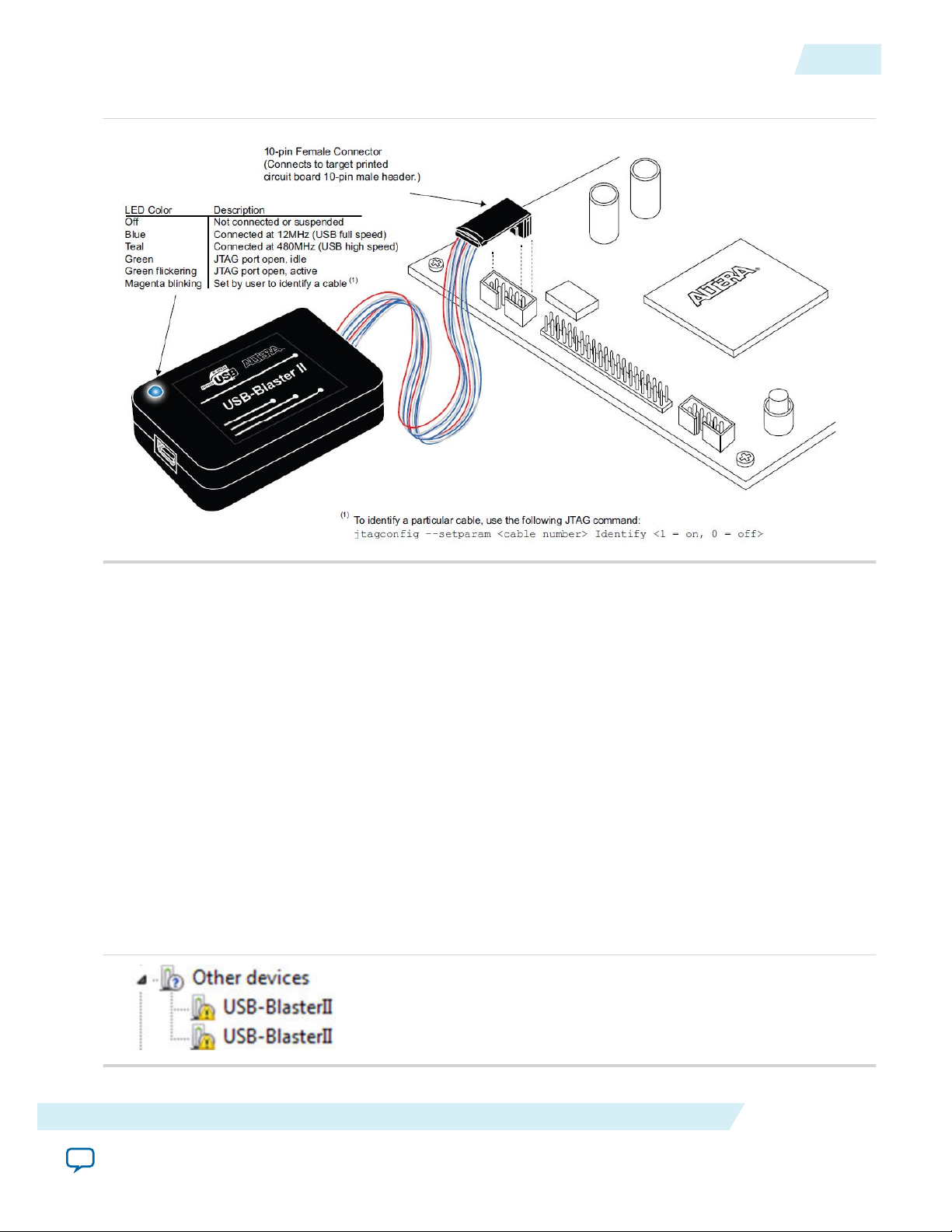
The USB-Blaster™ II download cable interfaces a USB port on a host computer to an Altera® FPGA
mounted on a printed circuit board. The download cable sends data from the PC to a standard 10-pin
header connected to the FPGA. You can use the download cable for the following:
• Iteratively download configuration data to a system during prototyping
• Program data into the system during production
• Advanced Encryption Standard (AES) key and fuse programming
Supported Devices and Systems
You can use the USB-Blaster II download cable to download configuration data to the following Altera
devices:
• Stratix® series FPGAs
• Cyclone® series FPGAs
• MAX® series CPLDs
• Arria® series FPGAs
You can perform in-system programming of the following devices:
• EPC4, EPC8, and EPC16 enhanced configuration devices
• EPCS1, EPCS4, EPCS16, EPCS64, and EPCS/Q128, EPCQ256, EPCQ-L and EPCQ512 serial configu‐
ration devices
The download cable supports target systems using the following:
• 5.0-V TTL, 3.3-V LVTTL/LVCMOS
• Single-ended I/O standards from 1.5 V to 3.3 V
Power Source Requirements
• 5.0 V from the USB cable
• Between 1.5 V and 5.0 V from the target circuit board
©
2015 Altera Corporation. All rights reserved. ALTERA, ARRIA, CYCLONE, ENPIRION, MAX, MEGACORE, NIOS, QUARTUS and STRATIX words and logos are
trademarks of Altera Corporation and registered in the U.S. Patent and Trademark Office and in other countries. All other words and logos identified as
trademarks or service marks are the property of their respective holders as described at www.altera.com/common/legal.html. Altera warrants performance
of its semiconductor products to current specifications in accordance with Altera's standard warranty, but reserves the right to make changes to any
products and services at any time without notice. Altera assumes no responsibility or liability arising out of the application or use of any information,
product, or service described herein except as expressly agreed to in writing by Altera. Altera customers are advised to obtain the latest version of device
specifications before relying on any published information and before placing orders for products or services.
ISO
9001:2008
Registered
Page 4

1-2
Software Requirements and Support
Software Requirements and Support
• Windows 7/8 (32-bit and 64-bit)
• Windows XP (32-bit and 64-bit)
• Windows Server 2008 R2 (64-bit)
• Linux platforms such as Red Hat Enterprise 5
Use the Quartus® Prime software version 14.0 or later to configure your device.
Note: Quartus Prime software version 13.1 supports most of the download cable’s capabilities. If you use
this version, install the latest patch for full compatibility.
The download cable also supports the following tools:
• Quartus Prime Programmer (and stand-alone version)
• Quartus Prime SignalTap® II Logic Analyzer (and stand-alone version)
• JTAG and debug tools supported by the JTAG Server. For example:
• System Console
• Nios II debugger
• ARM DS-5 debugger
UG-01150
2015.12.11
Installing the Download Cable for Configuration or Programming
1. Disconnect the power cable from the circuit board.
2. Connect the download cable to the USB port on your computer and to the USB-Blaster II port.
3. Connect the download cable to the 10-pin header on the device board.
4. Reconnect the power cable to reapply power to the circuit board.
Altera Corporation
Setting Up the USB-Blaster II Download Cable
Send Feedback
Page 5
UG-01150
2015.12.11
Installing the USB-Blaster II Driver on Windows 7/8 Systems
Figure 1-1: The USB-Blaster II Download Cable
1-3
Note: For plug and header dimensions, pin names, and operating conditions, see Chapter 2, USB-Blaster
II Download Cable Specifications.
Related Information
USB-Blaster II Download Cable Specifications on page 2-1
Installing the USB-Blaster II Driver on Windows 7/8 Systems
You must have system administration (administrator) privileges to install the USB-Blaster II download
cable drivers.
The download cable drivers are included in the Quartus Prime software installation. Before you begin the
installation, verify that the USB-Blaster II driver is located in your directory: \<Quartus Prime system
directory>\drivers\usb-blaster-ii.
1. Connect the download cable to your computer’s USB port.
When plugged in for the first time, a message appears stating Device driver software was not success‐
fully installed.
2. From the Windows Device Manager, locate Other devices and right-click the top USB-BlasterII.
Setting Up the USB-Blaster II Download Cable
Send Feedback
Altera Corporation
Page 6
1-4
Installing the USB-Blaster II Driver on Linux Systems
UG-01150
2015.12.11
You need to install drivers for each interface: one for the JTAG interface and one for the System
Console interface.
3. On the right-click menu, click Update Driver Software. The Update Driver Software - USB BlasterII
dialog appears.
4. Click Browse my computer for driver software to continue.
5. Click Browse… and browse to the location of the driver on your system: \<Quartus Prime system
directory>\drivers\usb-blaster-ii. Click OK.
6. Click Next to install the driver.
7. Click Install when asked if you want to install.
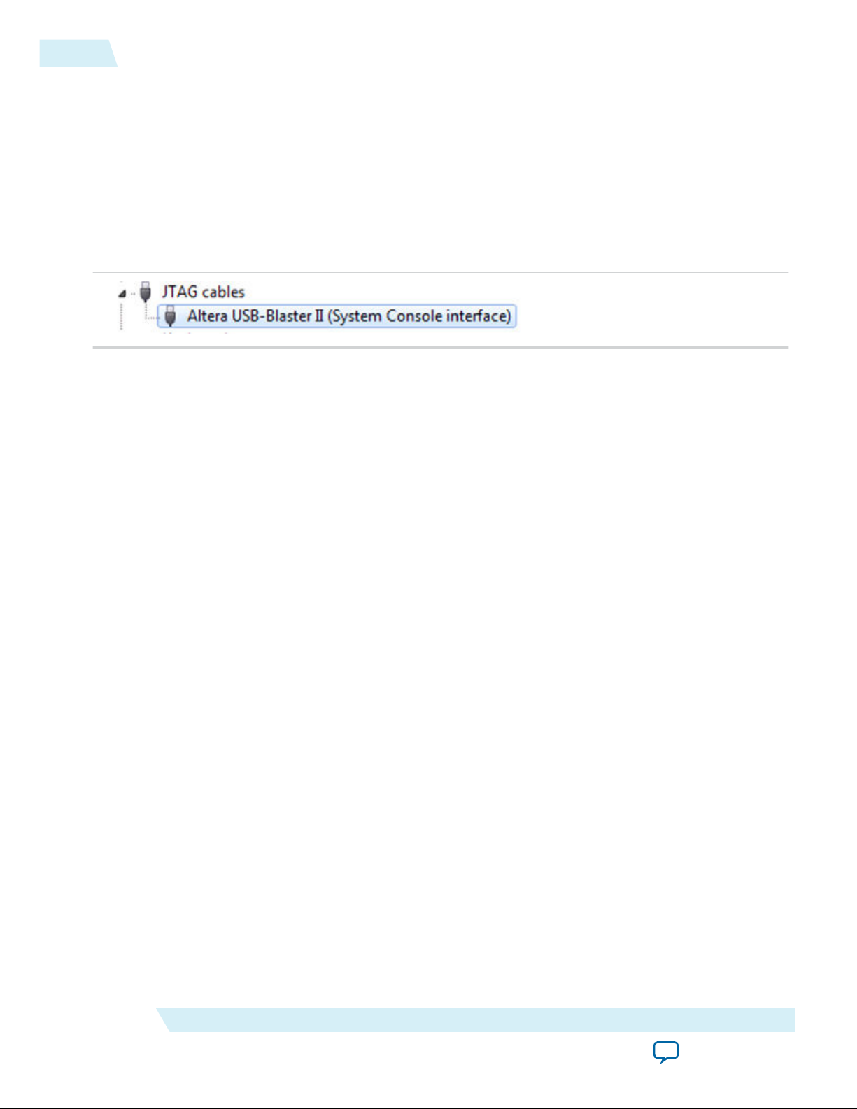
You should now have a JTAG cable showing in the Device Manager.
8. Now, install the driver for the other interface. Go back to step 2 and repeat the process for the other
USB-BlasterII device.
When you are finished, you will have added Altera USB-Blast II (JTAG interface) under JTAG cables.
Installing the USB-Blaster II Driver on Linux Systems
For Linux, the USB-Blaster II download cable supports Red Hat Enterprise 5 and above.
To access the download cable, the Quartus Prime software uses the built-in Red Hat USB drivers, the USB
file system (usbfs). By default, root is the only user allowed to use usbfs. You must have system adminis‐
tration (root) privileges to configure the USB-Blaster II download cable drivers.
1. Create a file named /etc/udev/rules.d/51-usbblaster.rules and add the following lines to it. (The .rules file
may already exist if you have installed an earlier USB-Blaster version.)
# USB-Blaster II
BUS=="usb", SYSFS{idVendor}=="09fb", SYSFS{idProduct}=="6010", MODE="0666"
BUS=="usb", SYSFS{idVendor}=="09fb", SYSFS{idProduct}=="6810", MODE="0666"
Caution:
2. Complete your installation by setting up the programming hardware in the Quartus Prime software.
Go to the “Setting Up the USB-Blaster II Hardware with the Quartus Prime Software” section on the
following page.
For more information about USB-Blaster II driver installation, refer to the Cable and Adapter Drivers
Information page.
Related Information
• Setting Up the USB-Blaster II Hardware with the Quartus Prime Software on page 1-5
• Cable and Adapter Drivers Information
There should be only three lines in this file, one starting with a comment and two starting
with BUS. Do not add extra line breaks to the .rules file.
Altera Corporation
Setting Up the USB-Blaster II Download Cable
Send Feedback
Page 7

UG-01150
2015.12.11
Installing the USB-Blaster II Driver on Windows XP Systems
Installing the USB-Blaster II Driver on Windows XP Systems
You must have system administration (administrator) privileges to install the USB-Blaster II download
cable driver.
The download cable drivers are included in the Quartus Prime software installation. Before you begin the
installation, verify that the USB-Blaster II driver is located in your directory: \<Quartus Prime system
directory>\drivers\usb-blaster-ii.
Setting Up the USB-Blaster II Hardware with the Quartus Prime Software
1. Start the Quartus Prime software.
2. From the Tools menu, click Programmer.
3. Click Hardware Setup.
4. Click the Hardware Settings tab.
5. From the Currently selected hardware list, select USB-Blaster II.
6. Click Close.
7. In the Mode list, choose an appropriate programming mode. The table below describes each mode.
Table 1-1: Programming Modes
1-5
Mode Mode Description
Joint Test Action Group (JTAG) Programs or configures all Altera devices supported by Quartus
Prime software via JTAG programming.
In-Socket Programming Not supported by the USB-Blaster II.
Passive Serial Programming Configures all Altera devices supported by Quartus Prime
software excluding enhanced configuration devices (EPC) and
serial configuration devices (EPCS/Q).
Active Serial Programming Programs a single EPCS1, EPCS4, EPCS16, EPCS64, EPCS/
Q128, EPCQ256, EPCQ-L and EPCQ512 device.
For detailed help on using the Quartus Prime Programmer, refer to the Quartus Prime Handbook.
Related Information
Quartus Prime Handbook
Setting Up the USB-Blaster II Download Cable
Send Feedback
Altera Corporation
Page 8

2015.12.11
www.altera.com
101 Innovation Drive, San Jose, CA 95134
USB-Blaster II Download Cable Specifications
2
UG-01150
Subscribe
Send Feedback
Voltage Requirements
The USB-Blaster II V
CC(TRGT)
Connect pull-up resistors to the same power supply as the USB-Blaster II: V
Table 2-1: USB-Blaster II V
Device Family USB-Blaster II VCC Voltage Required
CC(TRGT)
Arria GX As specified by V
Arria II GX As specified by V
Arria V As specified by V
Arria 10 As specified by V
Cyclone III As specified by V
Cyclone IV As specified by V
Cyclone V As specified by V
EPC4, EPC8, EPC16 3.3 V
pin must be connected to a specific voltage for the device being programmed.
Pin Voltage Requirements
for Cyclone IV E devices.
CC(TRGT)
CCSEL
or V
CCPD
Bank 3A
CCPD
or V
CCPGM
or V
CCA
. Bank 9 for Cyclone IV GX and Bank 1
CCIO
Bank 3A
CCPD
CCIO
CCIO
CCIO
of Bank 8C
.
EPCS1, EPCS4, EPCS16, EPCS64,
3.3 V
EPCS128
EPCS/Q16, EPCS/Q64, EPCS/Q128,
3.3 V
EPCQ256, EPCQ512
EPCQ-L 1.8 V
MAX II, MAX V As specified by V
MAX 10 As specified by V
Stratix II, Stratix II GX As specified by V
Stratix III, Stratix IV As specified by V
Stratix V As specified by V
©
2015 Altera Corporation. All rights reserved. ALTERA, ARRIA, CYCLONE, ENPIRION, MAX, MEGACORE, NIOS, QUARTUS and STRATIX words and logos are
trademarks of Altera Corporation and registered in the U.S. Patent and Trademark Office and in other countries. All other words and logos identified as
trademarks or service marks are the property of their respective holders as described at www.altera.com/common/legal.html. Altera warrants performance
of its semiconductor products to current specifications in accordance with Altera's standard warranty, but reserves the right to make changes to any
products and services at any time without notice. Altera assumes no responsibility or liability arising out of the application or use of any information,
product, or service described herein except as expressly agreed to in writing by Altera. Altera customers are advised to obtain the latest version of device
specifications before relying on any published information and before placing orders for products or services.
of Bank 1
CCIO
CCIO
CCSEL
CCPGM
CCPD
or V
CCPD
Bank 3A
ISO
9001:2008
Registered
Page 9

USB Interface
Chip
EPM570M100C5
I/Os
I/Os
V
CC
USB
Receptacle
LVDS
Drivers/Receivers
LVDS
Cabling
I/O
I/O
I/O
I/O
I/O
I/O
I/O
Voltage
Translator Circuitry
Pin1
10-Pin
Female Plug
V
CC (TRGT)
0.37 (9.4) Typ.
0.24 (6.1) Typ.
0.04 (1.0) Typ.
.10 (2.5)Sq.
0.70 (17.8) Typ.
0.15 (3.8) Typ.
.025
(.63)Sq.
1098765432
1
2-2
Cable-to-Board Connection
Cable-to-Board Connection
A standard USB cable connects to the USB port on the device.
Figure 2-1: USB-Blaster II Download Cable Block Diagram
USB-Blaster II Plug Connection
The 10-pin female plug connects to a 10-pin male header on the circuit board containing the target
device.
UG-01150
2015.12.11
Figure 2-2: USB-Blaster II 10-Pin Female Plug Dimensions - Inches & Millimeters
Altera Corporation
USB-Blaster II Download Cable Specifications
Send Feedback
Page 10

UG-01150
2015.12.11
10-Pin Female Plug Signal Names and Programming Modes
Figure 2-3: USB-Blaster II Dimension - Inches and Millimeters
2-3
10-Pin Female Plug Signal Names and Programming Modes
Table 2-2: 10-Pin II Female Plug Signal Names and Programming Modes
Pin
1 DCLK Clock signal DCLK Clock signal TCK Clock signal
2 GND Signal ground GND Signal
3 CONF_DONE Configuration
4 VCC(TRGT) Target power
5 nCONFIG Configuration
USB-Blaster II Download Cable Specifications
Send Feedback
Active Serial (AS) Mode Passive Serial (PS) Mode JTAG Mode
Signal Name Description Signal Name Description Signal Name Description
GND Signal ground
ground
done
supply
CONF_DONE Configuratio
n done
VCC(TRGT) Target
power
TDO Configuration
VCC(TRGT) Target power
supply
control
nCONFIG Configuratio
n control
TMS Configuration
done
supply
control
Altera Corporation
Page 11

0.025 (0.635) Sq.
0.235 (5.969)
0.100
Side View
0.100 (2.540)
Top View
A key notch is required.
2-4
Circuit Board Header Connection
UG-01150
2015.12.11
Pin
6 nCE Cyclone chip
7 DATAOUT Active serial
8 nCS Serial
9 ASDI Active serial
10 GND Signal ground GND Signal
Active Serial (AS) Mode Passive Serial (PS) Mode JTAG Mode
Signal Name Description Signal Name Description Signal Name Description
(1)
Cyclone chip
enable
out
tion device chip
select
in
enable
data out
configuration
device chip
select
data in
- Cyclone
chip enable
nSTATUS Active serial
data out
- Serial
configuratio
n device
chip select
DATA0 Active serial
data in
PROC_RST
- Active serial data
- Serial configura‐
TDI Active serial data
GND Signal ground
ground
Note: In JTAG mode, the PROC_RST pin can be used to trigger warm reset of the HPS block when
prompted via the ARM DS-5 debugger. PROC_RST is an active low signal and not an open collector
pin. As such, it is not recommended to connect PROC_RST to HPS_nRST directly. You should instead
connect this pin to a secondary device such as the MAX V CPLD, and use the device to manage the
reset network for HPS.
Circuit Board Header Connection
The 10-pin male header, which connects to the download cable's 10-pin female plug, has two rows of five
pins. The pins are connected to the device’s programming or configuration pins.
Caution:
Figure 2-4: 10-Pin Male Header Dimensions - Inches and Millimeters
If the header connection on the circuit board is a male receptacle, it must have a key notch.
Without a key notch, the 10-pin female plug will not connect. The following figure shows a
typical 10-pin male header with a key notch.
(1)
Altera Corporation
Use pin 6 for a hard processor reset under JTAG mode.
USB-Blaster II Download Cable Specifications
Send Feedback
Page 12

UG-01150
2015.12.11
Although a 10-pin surface mount header can be used for the download cable, Altera recommends using a
through-hole connector. Through-hole connectors hold up better under the repeated insertion and
removal.
Operating Conditions
The following tables summarize the maximum ratings, recommended operating conditions, and DC
operating conditions for the USB-Blaster II cable.
Table 2-3: USB-Blaster II Cable Absolute Maximum Ratings
Symbol Parameter Conditions Min Max Unit
Operating Conditions
2-5
V
CC(TRGT)
V
CC(USB)
I
I
I
I(USB)
I
o
Target supply voltage With respect to ground –0.5 6.5 V
USB supply voltage With respect to ground –0.5 6.0 V
Target side input current Pin 7 –100.0 100.0 mA
USB supply current VBUS – 200.0 mA
Target side output current Pins: 1, 5, 6, 8, 9 –50.0 50.0 mA
Table 2-4: USB-Blaster II Cable Recommended Operating Conditions
Symbol Parameter Conditions Min Max Unit
Target supply voltage, 5.0-V
— 4.75 5.25 V
operation
Target supply voltage, 3.3-V
— 3.0 3.6 V
operation
V
CC(TRGT)
Target supply voltage, 2.5-V
operation
Target supply voltage, 1.8-V
— 2.375 2.625 V
— 1.71 1.89 V
operation
Target supply voltage, 1.5-V
— 1.43 1.57 V
operation
Table 2-5: USB-Blaster II Cable DC Operating Conditions
Symbol Parameter Conditions Min Max Unit
High-level input voltage V
V
IH
USB-Blaster II Download Cable Specifications
Send Feedback
High-level input voltage V
CC(TRGT)
CC(TRGT)
>= 2.0 V 0.7 x
V
CC(TRGT
< 2.0 V 0.65 x
V
CC(TRGT
— V
)
— V
)
Altera Corporation
Page 13

2-6
Operating Conditions
Symbol Parameter Conditions Min Max Unit
UG-01150
2015.12.11
Low-level input voltage V
V
IL
Low-level input voltage V
5.0-V high-level output voltage V
CC(TRGT)
CC(TRGT)
CC(TRGT)
>= 2.0 V — 0.3 x
V
CC(TR
GT)
>= 2.0 V — 0.2 x
V
CC(TR
GT)
= 4.5 V, IOH = -32
3.8 — V
V
V
mA
3.3-V high-level output voltage V
CC(TRGT)
= 3.0 V, IOH = -24
2.4 — V
mA
V
OH
2.5-V high-level output voltage V
1.8-V high-level output voltage V
CC(TRGT)
mA
CC(TRGT)
= 2.3 V, IOH = -12
= 1.65 V, IOH = -8
1.9 — V
1.2 — V
mA
1.5-V high-level output voltage V
CC(TRGT)
= 1.4 V, IOH = -6
1.0 — V
mA
5.0-V low-level output voltage V
CC(TRGT)
= 4.5 V, IOL = 32
— 0.55 V
mA
3.3-V low-level output voltage V
CC(TRGT)
= 3.0 V, IOL = 24
— 0.55 V
mA
V
OL
I
CC(TRGT)
2.5-V low-level output voltage V
1.8-V low-level output voltage V
1.5-V low-level output voltage V
Operating current (No Load) V
CC(TRGT)
12mA
CC(TRGT)
8mA
CC(TRGT)
CC(TRGT)
= 2.3 V, IOL =
= 1.65 V, IOL =
— 0.3 V
— 0.45 V
= 1.4 V, IOL = 6mA — 0.3 V
=5.5 V — 316 uA
Altera Corporation
USB-Blaster II Download Cable Specifications
Send Feedback
Page 14

TCK
TDO
TCK
TMS
TDI
tJCP
JTAG OutputJTAG Inputs
tJCH tJCL
tJPCO
tJPSU_TMS
tJPSU_TDI
tJPH
UG-01150
2015.12.11
JTAG Timing Constraints and Waveforms
Figure 2-5: Timing Waveform for JTAG Signals (From Target Device Perspective)
JTAG Timing Constraints and Waveforms
2-7
To use the USB-Blaster II at the maximum capability (24 MHz), meet the timing constraints like in the
tabe below for the target device.
The timing constraints require that you consider device specifications as well as trace propagation delays.
If you do not follow the recommended constraints, you might encounter timing issues at 24 MHz. If the
target design cannot meet these constraints, reduce the possibility of timing issues by slowing the TCK
frequency. See “Changing the TCK Frequency” section for instructions on running the USB-Blaster II at a
slower speed.
Table 2-6: JTAG Timing Constraints for the Target Device
Symbol Parameter Min Max Unit
tJCP TCK clock period 41.67 — ns
USB-Blaster II Download Cable Specifications
tJCH TCK clock high
tJCL TCK clock low time 20.83 — ns
tJPCO JTAG port clock to
Send Feedback
time
JTAG Header
output
20.83 — ns
— 5.46 (2.5 V)
ns
2.66 (1.5 V)
Altera Corporation
Page 15

USB Blaster II
MAX
Device
Target Board
FPGA
11.575 ns 11.627 ns
JTAG Cable
JTAG
Header
Your Own
Measurement
Set Input
Delay
Board Traces
Launch/Latch
Registers
Launch/Latch
Registers
2-8
Changing the TCK Frequency
Symbol Parameter Min Max Unit
UG-01150
2015.12.11
tJPSU_TDI JTAG port setup
— 24.42 ns
time (TDI)
tJPSU_TMS JTAG port setup
— 26.43 ns
time (TMS)
tJPH JTAG port hold
— 17.25 ns
time
The simulated timing is based on a slow timing model, which is a worst-case scenario environment.
For device-specific JTAG timing information, refer to the related device data sheet.
Figure 2-6: USB-Blaster II Download Cable Timing Constraints
Changing the TCK Frequency
Altera Corporation
If you cannot meet 24 MHz, you must decrease the frequencies to 16-6 MHz. Below is some example code
to set the TCK maximum frequency to 6 MHz:
jtagconfig --setparam 1 JtagClock 6M
Related Information
• Changing the TCK Frequency on page 2-8
• Documentation: Data Sheets
The USB-Blaster II download cable has a default TCK frequency of 24 MHz. Where signal integrity and
timing prevents operating at 24 MHz, change the TCK frequency of the USB-Blaster II:
1. Open the command line interface with the Quartus Prime bin directory in your path (for example, C:\
altera\14.0\quartus\bin64).
2. Type the following command to change the TCK frequency:
jtagconfig --setparam <cable number> JtagClock <frequency><unit prefix>
USB-Blaster II Download Cable Specifications
Send Feedback
Page 16

UG-01150
2015.12.11
Changing the TCK Frequency
Where:
• <cable number> is the USB-Blaster II cable to be modified.
• <frequency> is the desired TCK frequency. Use one the following supported rates:
• 24 MHz
• 16 MHz
• 6 MHz
• 24/n MHz (between 10 kHz and 6 MHz, where n represents an integer value number)
• <unit prefix> is the unit prefix for the frequency (e.g., M for MHz).
Example for setting TCK maximum frequency to 6 MHz:
jtagconfig --setparam 1 JtagClock 6M
2-9
USB-Blaster II Download Cable Specifications
Send Feedback
Altera Corporation
Page 17

2015.12.11
www.altera.com
101 Innovation Drive, San Jose, CA 95134
Additional Information
A
UG-01150
Subscribe
Send Feedback
Document Revision History
Table A-1: USB-Blaster II Download Cable User Guide Revision History
Date Version Changes
December 2015 2015.12.11 Updated Sections:
• Supported Devices and Systems
• Setting Up the USB-Blaster II Hardware with the Quartus II
Software
• Voltage Requirements
• 10-Pin Female Plug Signal Names and Programming Modes
September 2014 1.2
• Added that the USB-II download cable supports Advanced
Encryption Standard (AES) key and fuse programming.
• Added magenta LED color to Figure 1-1 supporting multiple cable
use.
• Clarified a cross reference pointing to device-specific JTAG timing
information.
June 2014 1.1
January 2014 1.0 Initial release.
©
2015 Altera Corporation. All rights reserved. ALTERA, ARRIA, CYCLONE, ENPIRION, MAX, MEGACORE, NIOS, QUARTUS and STRATIX words and logos are
trademarks of Altera Corporation and registered in the U.S. Patent and Trademark Office and in other countries. All other words and logos identified as
trademarks or service marks are the property of their respective holders as described at www.altera.com/common/legal.html. Altera warrants performance
of its semiconductor products to current specifications in accordance with Altera's standard warranty, but reserves the right to make changes to any
products and services at any time without notice. Altera assumes no responsibility or liability arising out of the application or use of any information,
product, or service described herein except as expressly agreed to in writing by Altera. Altera customers are advised to obtain the latest version of device
specifications before relying on any published information and before placing orders for products or services.
• Added LED color table to Figure 1-1.
• Added “JTAG Timing Constraints and Waveforms” section.
• Added “Changing the TCK Frequency” section.
ISO
9001:2008
Registered
Page 18

A-2
Certification Statements
Certification Statements
RoHS Compliance
The table below lists hazardous substances included with the USB-Blaster download cable.
A value of 0 indicates that the concentration of the hazardous substance in all homogeneous materials in
the parts is below the relevant threshold as specified by the SJ/T11363-2006 standard.
Table A-2: Hazardous Substances and Concentration
UG-01150
2015.12.11
Part Name Lead (Pb) Cadmiu
m (Cd)
Electronic
0 0 0 0 0 0
Hexavelent
Chromium
(Cr6+)
Mercury
(Hg)
Polybromi‐
nated
biphenyls
(PBB)
Components
Populated
0 0 0 0 0 0
Circuit Board
Manufacturing
0 0 0 0 0 0
Process
Packing 0 0 0 0 0 0
USB 2.0 Certification
This product is USB 2.0 certified.
CE EMI Conformity Caution
This board is delivered conforming to relevant standards mandated by Directive 2004/108/EC. Because of
the nature of programmable logic devices, it is possible for the user to modify the kit in such a way as to
generate electromagnetic interference (EMI) that exceeds the limits established for this equipment. Any
EMI caused as the result of modifications to the delivered material is the responsibility of the user.
Polybrominated
diphenyl Ethers
(PBDE)
Altera Corporation
Additional Information
Send Feedback
 Loading...