

ALTERA Stratix V GX FPGA Service Manual
Stratix V GX FPGA Development Kit User Guide
Stratix V GX FPGA Development Kit
User Guide
101 Innovation Drive
San Jose, CA 95134
www.altera.com
UG-01103-1.2
Feedback Subscribe

© 2012 Altera Corporation. All rights reserved. ALTERA, ARRIA, CYCLONE, HARDCOPY, MAX, MEGACORE, NIOS, QUARTUS and STRATIX words and logos
are trademarks of Altera Corporation and registered in the U.S. Patent and Trademark Office and in other countries. All other words and logos identified as
trademarks or service marks are the property of their respective holders as described at www.altera.com/common/legal.html. Altera warrants performance of its
semiconductor products to current specifications in accordance with Altera's standard warranty, but reserves the right to make changes to any products and
services at any time without notice. Altera assumes no responsibility or liability arising out of the application or use of any information, product, or service
described herein except as expressly agreed to in writing by Altera. Altera customers are advised to obtain the latest version of device specifications before relying
on any published information and before placing orders for products or services.
ISO
9001:2008
Registered
July 2012 Altera Corporation Stratix V GX FPGA Development Kit
User Guide

Contents
Chapter 1. About This Kit
Kit Features . . . . . . . . . . . . . . . . . . . . . . . . . . . . . . . . . . . . . . . . . . . . . . . . . . . . . . . . . . . . . . . . . . . . . . . . . . . . 1–1
Hardware . . . . . . . . . . . . . . . . . . . . . . . . . . . . . . . . . . . . . . . . . . . . . . . . . . . . . . . . . . . . . . . . . . . . . . . . . . . . 1–1
Software . . . . . . . . . . . . . . . . . . . . . . . . . . . . . . . . . . . . . . . . . . . . . . . . . . . . . . . . . . . . . . . . . . . . . . . . . . . . . 1–2
Quartus II Software . . . . . . . . . . . . . . . . . . . . . . . . . . . . . . . . . . . . . . . . . . . . . . . . . . . . . . . . . . . . . . . . . 1–2
Stratix V GX FPGA Development Kit Installer . . . . . . . . . . . . . . . . . . . . . . . . . . . . . . . . . . . . . . . . . . 1–3
Chapter 2. Getting Started
Before You Begin . . . . . . . . . . . . . . . . . . . . . . . . . . . . . . . . . . . . . . . . . . . . . . . . . . . . . . . . . . . . . . . . . . . . . . . . 2–1
Inspect the Board . . . . . . . . . . . . . . . . . . . . . . . . . . . . . . . . . . . . . . . . . . . . . . . . . . . . . . . . . . . . . . . . . . . . . 2–1
References . . . . . . . . . . . . . . . . . . . . . . . . . . . . . . . . . . . . . . . . . . . . . . . . . . . . . . . . . . . . . . . . . . . . . . . . . . . . . . 2–2
Chapter 3. Software Installation
Installing the Quartus II Subscription Edition Software . . . . . . . . . . . . . . . . . . . . . . . . . . . . . . . . . . . . . . . 3–1
Licensing Considerations . . . . . . . . . . . . . . . . . . . . . . . . . . . . . . . . . . . . . . . . . . . . . . . . . . . . . . . . . . . . . . 3–1
Installing the Stratix V GX FPGA Development Kit . . . . . . . . . . . . . . . . . . . . . . . . . . . . . . . . . . . . . . . . . . 3–2
Installing the USB-Blaster II Driver . . . . . . . . . . . . . . . . . . . . . . . . . . . . . . . . . . . . . . . . . . . . . . . . . . . . . . . . 3–3
Chapter 4. Development Board Setup
Setting Up the Board . . . . . . . . . . . . . . . . . . . . . . . . . . . . . . . . . . . . . . . . . . . . . . . . . . . . . . . . . . . . . . . . . . . . . 4–1
Factory Default Switch Settings . . . . . . . . . . . . . . . . . . . . . . . . . . . . . . . . . . . . . . . . . . . . . . . . . . . . . . . . . . . 4–2
Chapter 5. Board Update Portal
Connecting to the Board Update Portal Web Page . . . . . . . . . . . . . . . . . . . . . . . . . . . . . . . . . . . . . . . . . . . 5–1
Using the Board Update Portal to Update User Designs . . . . . . . . . . . . . . . . . . . . . . . . . . . . . . . . . . . . . . 5–2
Chapter 6. Board Test System
Preparing the Board . . . . . . . . . . . . . . . . . . . . . . . . . . . . . . . . . . . . . . . . . . . . . . . . . . . . . . . . . . . . . . . . . . . . . 6–2
Running the Board Test System . . . . . . . . . . . . . . . . . . . . . . . . . . . . . . . . . . . . . . . . . . . . . . . . . . . . . . . . . . . 6–2
Using the Board Test System . . . . . . . . . . . . . . . . . . . . . . . . . . . . . . . . . . . . . . . . . . . . . . . . . . . . . . . . . . . . . . 6–3
The Configure Menu . . . . . . . . . . . . . . . . . . . . . . . . . . . . . . . . . . . . . . . . . . . . . . . . . . . . . . . . . . . . . . . . . . 6–3
The System Info Tab . . . . . . . . . . . . . . . . . . . . . . . . . . . . . . . . . . . . . . . . . . . . . . . . . . . . . . . . . . . . . . . . . . . 6–3
Board Information . . . . . . . . . . . . . . . . . . . . . . . . . . . . . . . . . . . . . . . . . . . . . . . . . . . . . . . . . . . . . . . . . . 6–3
MAX V Registers . . . . . . . . . . . . . . . . . . . . . . . . . . . . . . . . . . . . . . . . . . . . . . . . . . . . . . . . . . . . . . . . . . . 6–4
JTAG Chain . . . . . . . . . . . . . . . . . . . . . . . . . . . . . . . . . . . . . . . . . . . . . . . . . . . . . . . . . . . . . . . . . . . . . . . . 6–5
Qsys Memory Map . . . . . . . . . . . . . . . . . . . . . . . . . . . . . . . . . . . . . . . . . . . . . . . . . . . . . . . . . . . . . . . . . 6–5
The GPIO Tab . . . . . . . . . . . . . . . . . . . . . . . . . . . . . . . . . . . . . . . . . . . . . . . . . . . . . . . . . . . . . . . . . . . . . . . . 6–6
Character LCD . . . . . . . . . . . . . . . . . . . . . . . . . . . . . . . . . . . . . . . . . . . . . . . . . . . . . . . . . . . . . . . . . . . . . 6–6
User DIP Switches . . . . . . . . . . . . . . . . . . . . . . . . . . . . . . . . . . . . . . . . . . . . . . . . . . . . . . . . . . . . . . . . . . 6–6
User LEDs . . . . . . . . . . . . . . . . . . . . . . . . . . . . . . . . . . . . . . . . . . . . . . . . . . . . . . . . . . . . . . . . . . . . . . . . . 6–7
Push Button Switches . . . . . . . . . . . . . . . . . . . . . . . . . . . . . . . . . . . . . . . . . . . . . . . . . . . . . . . . . . . . . . . 6–7
The Flash Tab . . . . . . . . . . . . . . . . . . . . . . . . . . . . . . . . . . . . . . . . . . . . . . . . . . . . . . . . . . . . . . . . . . . . . . . . 6–7
Read . . . . . . . . . . . . . . . . . . . . . . . . . . . . . . . . . . . . . . . . . . . . . . . . . . . . . . . . . . . . . . . . . . . . . . . . . . . . . . 6–8
Write . . . . . . . . . . . . . . . . . . . . . . . . . . . . . . . . . . . . . . . . . . . . . . . . . . . . . . . . . . . . . . . . . . . . . . . . . . . . . 6–8
Random Test . . . . . . . . . . . . . . . . . . . . . . . . . . . . . . . . . . . . . . . . . . . . . . . . . . . . . . . . . . . . . . . . . . . . . . . 6–8
CFI Query . . . . . . . . . . . . . . . . . . . . . . . . . . . . . . . . . . . . . . . . . . . . . . . . . . . . . . . . . . . . . . . . . . . . . . . . . 6–8
Increment Test . . . . . . . . . . . . . . . . . . . . . . . . . . . . . . . . . . . . . . . . . . . . . . . . . . . . . . . . . . . . . . . . . . . . . 6–8
Reset . . . . . . . . . . . . . . . . . . . . . . . . . . . . . . . . . . . . . . . . . . . . . . . . . . . . . . . . . . . . . . . . . . . . . . . . . . . . . . 6–8
July 2012 Altera Corporation Stratix V GX FPGA Development Kit
User Guide

iv Contents
Erase . . . . . . . . . . . . . . . . . . . . . . . . . . . . . . . . . . . . . . . . . . . . . . . . . . . . . . . . . . . . . . . . . . . . . . . . . . . . . . 6–8
Flash Memory Map . . . . . . . . . . . . . . . . . . . . . . . . . . . . . . . . . . . . . . . . . . . . . . . . . . . . . . . . . . . . . . . . . 6–8
The DDR3 Tab . . . . . . . . . . . . . . . . . . . . . . . . . . . . . . . . . . . . . . . . . . . . . . . . . . . . . . . . . . . . . . . . . . . . . . . . 6–9
Start . . . . . . . . . . . . . . . . . . . . . . . . . . . . . . . . . . . . . . . . . . . . . . . . . . . . . . . . . . . . . . . . . . . . . . . . . . . . . . 6–9
Stop . . . . . . . . . . . . . . . . . . . . . . . . . . . . . . . . . . . . . . . . . . . . . . . . . . . . . . . . . . . . . . . . . . . . . . . . . . . . . . 6–9
Performance Indicators . . . . . . . . . . . . . . . . . . . . . . . . . . . . . . . . . . . . . . . . . . . . . . . . . . . . . . . . . . . . . . 6–9
Error Control . . . . . . . . . . . . . . . . . . . . . . . . . . . . . . . . . . . . . . . . . . . . . . . . . . . . . . . . . . . . . . . . . . . . . 6–10
Number of Addresses to Write and Read . . . . . . . . . . . . . . . . . . . . . . . . . . . . . . . . . . . . . . . . . . . . . 6–10
Data Type . . . . . . . . . . . . . . . . . . . . . . . . . . . . . . . . . . . . . . . . . . . . . . . . . . . . . . . . . . . . . . . . . . . . . . . . 6–10
Read and Write Control . . . . . . . . . . . . . . . . . . . . . . . . . . . . . . . . . . . . . . . . . . . . . . . . . . . . . . . . . . . . 6–10
The QDRII+ Tab . . . . . . . . . . . . . . . . . . . . . . . . . . . . . . . . . . . . . . . . . . . . . . . . . . . . . . . . . . . . . . . . . . . . . 6–11
Start . . . . . . . . . . . . . . . . . . . . . . . . . . . . . . . . . . . . . . . . . . . . . . . . . . . . . . . . . . . . . . . . . . . . . . . . . . . . . 6–11
Stop . . . . . . . . . . . . . . . . . . . . . . . . . . . . . . . . . . . . . . . . . . . . . . . . . . . . . . . . . . . . . . . . . . . . . . . . . . . . . 6–11
Performance Indicators . . . . . . . . . . . . . . . . . . . . . . . . . . . . . . . . . . . . . . . . . . . . . . . . . . . . . . . . . . . . . 6–12
Error Control . . . . . . . . . . . . . . . . . . . . . . . . . . . . . . . . . . . . . . . . . . . . . . . . . . . . . . . . . . . . . . . . . . . . . 6–12
Number of Addresses to Write and Read . . . . . . . . . . . . . . . . . . . . . . . . . . . . . . . . . . . . . . . . . . . . . 6–12
Data Type . . . . . . . . . . . . . . . . . . . . . . . . . . . . . . . . . . . . . . . . . . . . . . . . . . . . . . . . . . . . . . . . . . . . . . . . 6–12
The XCVR1 Tab . . . . . . . . . . . . . . . . . . . . . . . . . . . . . . . . . . . . . . . . . . . . . . . . . . . . . . . . . . . . . . . . . . . . . . 6–13
Status . . . . . . . . . . . . . . . . . . . . . . . . . . . . . . . . . . . . . . . . . . . . . . . . . . . . . . . . . . . . . . . . . . . . . . . . . . . . 6–13
Port . . . . . . . . . . . . . . . . . . . . . . . . . . . . . . . . . . . . . . . . . . . . . . . . . . . . . . . . . . . . . . . . . . . . . . . . . . . . . . 6–14
PMA Setting . . . . . . . . . . . . . . . . . . . . . . . . . . . . . . . . . . . . . . . . . . . . . . . . . . . . . . . . . . . . . . . . . . . . . . 6–14
Data Type . . . . . . . . . . . . . . . . . . . . . . . . . . . . . . . . . . . . . . . . . . . . . . . . . . . . . . . . . . . . . . . . . . . . . . . . 6–14
Error Control . . . . . . . . . . . . . . . . . . . . . . . . . . . . . . . . . . . . . . . . . . . . . . . . . . . . . . . . . . . . . . . . . . . . . 6–15
Start . . . . . . . . . . . . . . . . . . . . . . . . . . . . . . . . . . . . . . . . . . . . . . . . . . . . . . . . . . . . . . . . . . . . . . . . . . . . . 6–15
Stop . . . . . . . . . . . . . . . . . . . . . . . . . . . . . . . . . . . . . . . . . . . . . . . . . . . . . . . . . . . . . . . . . . . . . . . . . . . . . 6–15
Performance Indicators . . . . . . . . . . . . . . . . . . . . . . . . . . . . . . . . . . . . . . . . . . . . . . . . . . . . . . . . . . . . . 6–15
The XCVR2 Tab . . . . . . . . . . . . . . . . . . . . . . . . . . . . . . . . . . . . . . . . . . . . . . . . . . . . . . . . . . . . . . . . . . . . . . 6–16
Status . . . . . . . . . . . . . . . . . . . . . . . . . . . . . . . . . . . . . . . . . . . . . . . . . . . . . . . . . . . . . . . . . . . . . . . . . . . . 6–16
Port . . . . . . . . . . . . . . . . . . . . . . . . . . . . . . . . . . . . . . . . . . . . . . . . . . . . . . . . . . . . . . . . . . . . . . . . . . . . . . 6–17
PMA Setting . . . . . . . . . . . . . . . . . . . . . . . . . . . . . . . . . . . . . . . . . . . . . . . . . . . . . . . . . . . . . . . . . . . . . . 6–17
Data Type . . . . . . . . . . . . . . . . . . . . . . . . . . . . . . . . . . . . . . . . . . . . . . . . . . . . . . . . . . . . . . . . . . . . . . . . 6–17
Error Control . . . . . . . . . . . . . . . . . . . . . . . . . . . . . . . . . . . . . . . . . . . . . . . . . . . . . . . . . . . . . . . . . . . . . 6–18
Start . . . . . . . . . . . . . . . . . . . . . . . . . . . . . . . . . . . . . . . . . . . . . . . . . . . . . . . . . . . . . . . . . . . . . . . . . . . . . 6–18
Stop . . . . . . . . . . . . . . . . . . . . . . . . . . . . . . . . . . . . . . . . . . . . . . . . . . . . . . . . . . . . . . . . . . . . . . . . . . . . . 6–18
Performance Indicators . . . . . . . . . . . . . . . . . . . . . . . . . . . . . . . . . . . . . . . . . . . . . . . . . . . . . . . . . . . . . 6–18
The XCVR3 Tab . . . . . . . . . . . . . . . . . . . . . . . . . . . . . . . . . . . . . . . . . . . . . . . . . . . . . . . . . . . . . . . . . . . . . . 6–19
Status . . . . . . . . . . . . . . . . . . . . . . . . . . . . . . . . . . . . . . . . . . . . . . . . . . . . . . . . . . . . . . . . . . . . . . . . . . . . 6–19
Port . . . . . . . . . . . . . . . . . . . . . . . . . . . . . . . . . . . . . . . . . . . . . . . . . . . . . . . . . . . . . . . . . . . . . . . . . . . . . . 6–20
PMA Setting . . . . . . . . . . . . . . . . . . . . . . . . . . . . . . . . . . . . . . . . . . . . . . . . . . . . . . . . . . . . . . . . . . . . . . 6–20
Data Type . . . . . . . . . . . . . . . . . . . . . . . . . . . . . . . . . . . . . . . . . . . . . . . . . . . . . . . . . . . . . . . . . . . . . . . . 6–20
Error Control . . . . . . . . . . . . . . . . . . . . . . . . . . . . . . . . . . . . . . . . . . . . . . . . . . . . . . . . . . . . . . . . . . . . . 6–21
Start . . . . . . . . . . . . . . . . . . . . . . . . . . . . . . . . . . . . . . . . . . . . . . . . . . . . . . . . . . . . . . . . . . . . . . . . . . . . . 6–21
Stop . . . . . . . . . . . . . . . . . . . . . . . . . . . . . . . . . . . . . . . . . . . . . . . . . . . . . . . . . . . . . . . . . . . . . . . . . . . . . 6–21
Performance Indicators . . . . . . . . . . . . . . . . . . . . . . . . . . . . . . . . . . . . . . . . . . . . . . . . . . . . . . . . . . . . . 6–21
The Power Monitor . . . . . . . . . . . . . . . . . . . . . . . . . . . . . . . . . . . . . . . . . . . . . . . . . . . . . . . . . . . . . . . . . . . . . 6–21
General Information . . . . . . . . . . . . . . . . . . . . . . . . . . . . . . . . . . . . . . . . . . . . . . . . . . . . . . . . . . . . . . . 6–22
Temperature Information . . . . . . . . . . . . . . . . . . . . . . . . . . . . . . . . . . . . . . . . . . . . . . . . . . . . . . . . . . . 6–23
Power Information . . . . . . . . . . . . . . . . . . . . . . . . . . . . . . . . . . . . . . . . . . . . . . . . . . . . . . . . . . . . . . . . . 6–23
Power Graph . . . . . . . . . . . . . . . . . . . . . . . . . . . . . . . . . . . . . . . . . . . . . . . . . . . . . . . . . . . . . . . . . . . . . 6–23
Graph Settings . . . . . . . . . . . . . . . . . . . . . . . . . . . . . . . . . . . . . . . . . . . . . . . . . . . . . . . . . . . . . . . . . . . . 6–23
Reset . . . . . . . . . . . . . . . . . . . . . . . . . . . . . . . . . . . . . . . . . . . . . . . . . . . . . . . . . . . . .
. . . . . . . . . . . . . . . . 6–23
The Clock Control . . . . . . . . . . . . . . . . . . . . . . . . . . . . . . . . . . . . . . . . . . . . . . . . . . . . . . . . . . . . . . . . . . . . . . 6–23
Read . . . . . . . . . . . . . . . . . . . . . . . . . . . . . . . . . . . . . . . . . . . . . . . . . . . . . . . . . . . . . . . . . . . . . . . . . . . . . 6–24
Default . . . . . . . . . . . . . . . . . . . . . . . . . . . . . . . . . . . . . . . . . . . . . . . . . . . . . . . . . . . . . . . . . . . . . . . . . . . 6–25
Stratix V GX FPGA Development Kit July 2012 Altera Corporation
User Guide

Contents v
Set New Frequency . . . . . . . . . . . . . . . . . . . . . . . . . . . . . . . . . . . . . . . . . . . . . . . . . . . . . . . . . . . . . . . . 6–25
Configuring the FPGA Using the Quartus II Programmer . . . . . . . . . . . . . . . . . . . . . . . . . . . . . . . . . . . . 6–25
Appendix A. Programming the Flash Memory Device
CFI Flash Memory Map . . . . . . . . . . . . . . . . . . . . . . . . . . . . . . . . . . . . . . . . . . . . . . . . . . . . . . . . . . . . . . . . . A–1
Preparing Design Files for Flash Programming . . . . . . . . . . . . . . . . . . . . . . . . . . . . . . . . . . . . . . . . . . . . . A–2
Creating Flash Files Using the Nios II EDS . . . . . . . . . . . . . . . . . . . . . . . . . . . . . . . . . . . . . . . . . . . . . . A–2
Programming Flash Memory Using the Board Update Portal . . . . . . . . . . . . . . . . . . . . . . . . . . . . . . . . . A–3
Programming Flash Memory Using the Nios II EDS . . . . . . . . . . . . . . . . . . . . . . . . . . . . . . . . . . . . . . . . . A–3
Restoring the Flash Device to the Factory Settings . . . . . . . . . . . . . . . . . . . . . . . . . . . . . . . . . . . . . . . . . . A–4
Restoring the MAX V CPLD to the Factory Settings . . . . . . . . . . . . . . . . . . . . . . . . . . . . . . . . . . . . . . . . . A–5
Additional Information
Document Revision History . . . . . . . . . . . . . . . . . . . . . . . . . . . . . . . . . . . . . . . . . . . . . . . . . . . . . . . . . . . Info–1
How to Contact Altera . . . . . . . . . . . . . . . . . . . . . . . . . . . . . . . . . . . . . . . . . . . . . . . . . . . . . . . . . . . . . . . . Info–1
Typographic Conventions . . . . . . . . . . . . . . . . . . . . . . . . . . . . . . . . . . . . . . . . . . . . . . . . . . . . . . . . . . . . . Info–1
July 2012 Altera Corporation Stratix V GX FPGA Development Kit
User Guide

vi Contents
Stratix V GX FPGA Development Kit July 2012 Altera Corporation
User Guide

1. About This Kit
The Altera® Stratix®V GX FPGA Development Kit is a complete design environment
that includes both the hardware and software you need to develop Stratix V GX
FPGA designs. The following list describes what you can accomplish with the kit:
■ Test signal quality of the FPGA transceiver I/Os (10 Gbps+).
■ Develop and test PCI Express
■ Develop and test memory subsystems consisting of SyncFlash, DDR3, and
QDRII+.
■ Develop and test SDI with the embedded 75-ohm 3G SDI transceivers.
■ Develop embedded designs utilizing the Nios
■ Develop and test network designs utilizing Triple Speed Ethernet MegaCore
external RJ-45 jack.
■ Develop and test optical networking designs using the 10G and 40G Ethernet
MAC MegaCores and the QSFP Optical Interface.
®
(PCIe) 3.0 designs.
®
II processor and external memory.
®
and
Kit Features
Hardware
■ Take advantage of the modular and scalable design by using the high-speed
mezzanine card (HSMC) connectors to interface to over 40 different HSMCs
provided by Altera partners, supporting protocols such as Serial RapidIO
®
,
10 Gigabit Ethernet, SONET, Common Public Radio Interface (CPRI), Open Base
Station Architecture Initiative (OBSAI) and others.
■ Measure the FPGA's power consumption.
■ Control twelve different programmable clock oscillators using the Clock Control
GUI.
This section briefly describes the Stratix V GX FPGA Development Kit contents.
The Stratix V GX FPGA Development Kit includes the following hardware:
■ Stratix V GX FPGA development board—A development platform that allows you
to develop and prototype hardware designs running on the Stratix V GX FPGA.
f For detailed information about the board components and interfaces, refer
to the Stratix V GX FPGA Development Board Reference Manual.
■ HSMC loopback board—A daughtercard that allows for loopback testing all
signals on the HSMC interface using the Board Test System.
July 2012 Altera Corporation Stratix V GX FPGA Development Kit
User Guide

1–2 Chapter 1: About This Kit
■ Power supply and cables—The kit includes the following items:
■ Power supply and AC adapters for North America/Japan, Europe, and the
Kit Features
United Kingdom
■ Standard USB A to micro-USB cable
■ Ethernet cable
■ 75 Ω SMB video cable
Software
The software for this kit, described in the following sections, is available on the Altera
website for immediate downloading. You can also request to have Altera mail the
software to you on DVDs.
Quartus II Software
Your kit includes a license for the Development Kit Edition (DKE) of the Quartus II
software (Windows platform only). For one year, this license entitles you to most of
the features of the Subscription Edition (excluding the IP Base Suite).
1 After the year, your DKE license will no longer be valid and you will not be permitted
to use this version of the Quartus II software. To continue using the Quartus II
software, you should download the free Quartus II Web edition or purchase a
subscription to Quartus II software. For more information, refer to the Design
Software page of the Altera website.
The Quartus II Development Kit Edition (DKE) software includes the following items:
■ Quartus II Software—The Quartus II software, including the Qsys system
integration tool, provides a comprehensive environment for network on a chip
(NoC) design. The Quartus II software integrates into nearly any design
environment and provides interfaces to industry-standard EDA tools.
■ MegaCore
®
IP Library—A library that contains Altera IP MegaCore functions. You
can evaluate MegaCore functions by using the OpenCore Plus feature to do the
following:
■ Simulate behavior of a MegaCore function within your system.
■ Verify functionality of your design, and quickly and easily evaluate its size and
speed.
■ Generate time-limited device programming files for designs that include
MegaCore functions.
■ Program a device and verify your design in hardware.
1 The OpenCore Plus hardware evaluation feature is an evaluation tool for
prototyping only. You must purchase a license to use a MegaCore function
in production.
f For more information about OpenCore Plus, refer to AN 320: OpenCore Plus
Evaluation of Megafunctions.
Stratix V GX FPGA Development Kit July 2012 Altera Corporation
User Guide

Chapter 1: About This Kit 1–3
Kit Features
■ Nios
®
II Embedded Design Suite (EDS)—A full-featured set of tools that allows
you to develop embedded software for the Nios II processor which you can
include in your Altera FPGA designs.
Stratix V GX FPGA Development Kit Installer
The license-free Stratix V GX FPGA Development Kit installer includes all the
documentation and design examples for the kit.
For information on installing the Development Kit Installer, refer to “Software
Installation” on page 3–1.
July 2012 Altera Corporation Stratix V GX FPGA Development Kit
User Guide

1–4 Chapter 1: About This Kit
Kit Features
Stratix V GX FPGA Development Kit July 2012 Altera Corporation
User Guide

The remaining chapters in this user guide lead you through the following
Stratix V GX FPGA development board setup steps:
■ Inspecting the contents of the kit
■ Installing the design and kit software
■ Setting up, powering up, and verifying correct operation of the FPGA
■ Configuring the Stratix V GX FPGA
■ Running the Board Test System designs
f For complete information about the FPGA development board, refer to the
Stratix V GX FPGA Development Board Reference Manual.
Before You Begin
2. Getting Started
development board
Before using the kit or installing the software, check the kit contents and inspect the
board to verify that you received all of the items listed in “Kit Features” on page 1–1.
If any of the items are missing, contact Altera before you proceed.
Inspect the Board
To inspect the board, perform the following steps:
1. Place the board on an anti-static surface and inspect it to ensure that it has not been
damaged during shipment.
c Without proper anti-static handling, you can damage the board.
2. Verify that all components are on the board and appear intact.
1 In typical applications with the Stratix V GX FPGA development board, a heat sink is
not necessary. However, under extreme conditions or for engineering sample silicon
the board might require additional cooling to stay within operating temperature
guidelines. The board has two holes near the FPGA that accommodate many different
heat sinks, including the Dynatron CHR-152. You can perform power consumption
and thermal modeling to determine whether your application requires additional
cooling. For information about measuring board and FPGA temperature in real time,
refer to “The Power Monitor” on page 6–21.
f For more information about power consumption and thermal modeling, refer to
AN 358: Thermal Management for FPGAs.
July 2012 Altera Corporation Stratix V GX FPGA Development Kit
User Guide

2–2 Chapter 2: Getting Started
References
References
Use the following links to check the Altera website for other related information:
■ For the latest board design files and reference designs, refer to the Stratix V GX
FPGA Development Kit page.
■ For additional daughter cards available for purchase, refer to the Development
Board Daughtercards page.
■ For the Stratix V GX device documentation, refer to the Literature: Stratix V
Devices page.
■ To purchase devices from the eStore, refer to the Devices page.
■ For Stratix V GX OrCAD symbols, refer to the Capture CIS Symbols page.
■ For Nios II 32-bit embedded processor solutions, refer to the Embedded
Processing page.
Stratix V GX FPGA Development Kit July 2012 Altera Corporation
User Guide

3. Software Installation
This chapter explains how to install the following software:
■ Quartus II Subscription Edition Software
■ Stratix V GX FPGA Development Kit
■ USB-Blaster™ II driver
Installing the Quartus II Subscription Edition Software
Included in the Quartus II Subscription Edition Software are the Quartus II software
(including Qsys), the Nios II EDS, and the MegaCore IP Library. To install the Altera
development tools, perform the following steps:
1. Download the Quartus II Subscription Edition Software from the Quartus II
Subscription Edition Software page of the Altera website. Alternatively, you can
request a DVD from the Altera IP and Software DVD Request Form page of the
Altera website.
2. Follow the on-screen instructions to complete the installation process.
f If you have difficulty installing the Quartus II software, refer to Altera Software
Installation and Licensing Manual.
Licensing Considerations
Purchasing this kit entitles you to a one-year license for the Development Kit Edition
(DKE) of the Quartus II software.
1 After the year, your DKE license will no longer be valid and you will not be permitted
to use this version of the Quartus II software. To continue using the Quartus II
software, you should download the free Quartus II Web edition or purchase a
subscription to Quartus II software.
Before using the Quartus II software, you must activate your license, identify specific
users and computers, and obtain and install a license file.
If you already have a licensed version of the subscription edition, you can use that
license file with this kit. If not, you need to obtain and install a license file. To begin,
go to the Self Service Licensing Center page of the Altera website, log into or create
your myAltera account, and take the following actions:
1. On the Activate Products page, enter the serial number provided with your
development kit in the License Activation Code box.
1 Your serial number is printed on the development kit box below the bottom
bar code. The number is consists of alphanumeric characters, such as
5SPCIexxxxxxxx, and does not contain hyphens.
July 2012 Altera Corporation Stratix V GX FPGA Development Kit
User Guide

3–2 Chapter 3: Software Installation
Installing the Stratix V GX FPGA Development Kit
2. Consult the Activate Products table, to determine how to proceed.
a. If the administrator listed for your product is someone other than you, skip the
remaining steps and contact your administrator to become a licensed user.
b. If the administrator listed for your product is you, proceed to step 3.
c. If the administrator listed for your product is Stocking, activate the product,
making you the administrator, and proceed to step 3.
3. Use the Create New License page to license your product for a specific user (you)
on specific computers. The Manage Computers and Manage Users pages allow
you to add users and computers not already present in the licensing system.
1 To license the Quartus II software, you need your computer’s network
interface card (NIC) ID, a number that uniquely identifies your computer.
On the computer you use to run the Quartus II software, type
/all
at a command prompt to determine the NIC ID. Your NIC ID is the
ipconfig
12-digit hexadecimal number on the Physical Address line.
4. When licensing is complete, Altera emails a license.dat file to you. Store the file on
your computer and use the License Setup page of the Options dialog box in the
Quartus_II software to enable the software.
f For complete licensing details, refer to Altera Software Installation and Licensing Manual.
Installing the Stratix V GX FPGA Development Kit
To install the Stratix V GX FPGA Development Kit, perform the following steps:
1. Download the Stratix V GX FPGA Development Kit installer from the Stratix V GX
FPGA Development Kit page of the Altera website. Alternatively, you can request
a development kit DVD from the Altera Kit Installations DVD Request Form page
of the Altera website.
2. Run the Stratix V GX FPGA Development Kit installer.
3. Follow the on-screen instructions to complete the installation process. Be sure that
the installation directory you choose is in the same relative location to the
Quartus II software installation.
Stratix V GX FPGA Development Kit July 2012 Altera Corporation
User Guide
Chapter 3: Software Installation 3–3
<install dir>
documents
board_design_files
The default Windows installation directory is C:\altera\
<version>
\.
examples
factory_recovery
demos
kits
stratixVGX_5sgxea7kf40_fpga
Installing the USB-Blaster II Driver
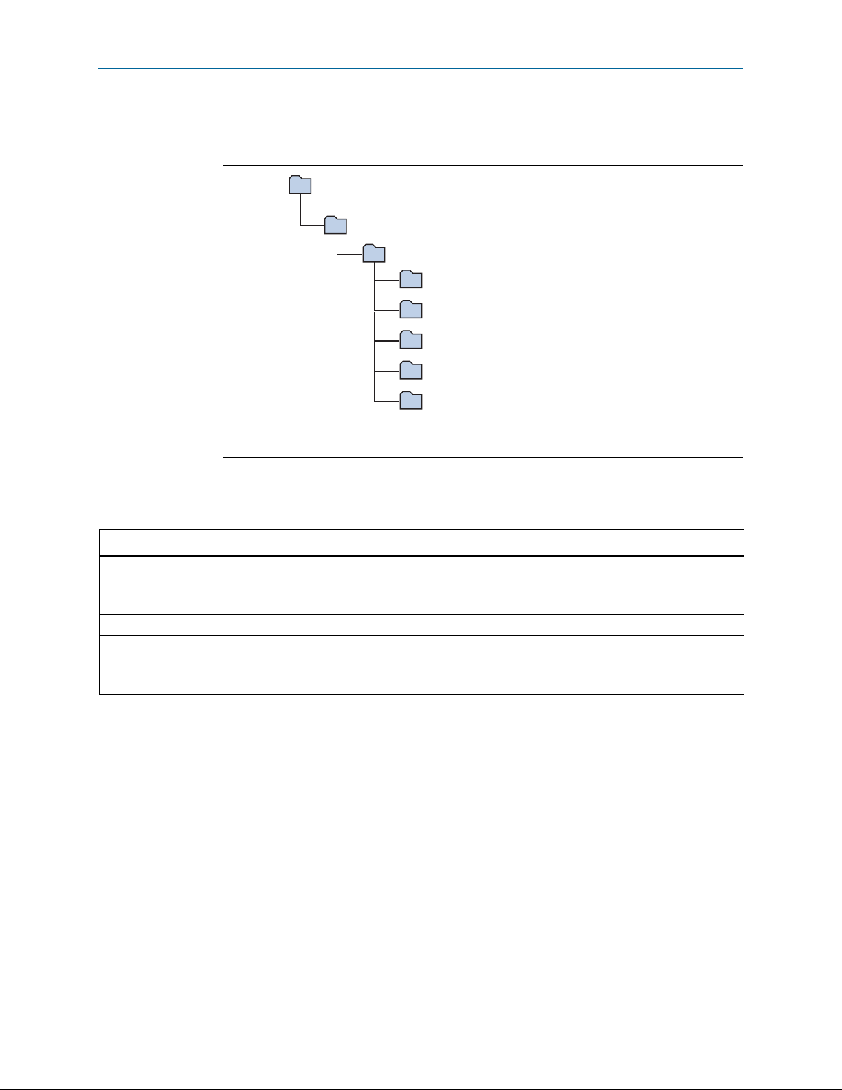
The installation program creates the Stratix V GX FPGA Development Kit directory
structure shown in Figure 3–1.
Figure 3–1. Stratix V GX FPGA Development Kit Installed Directory Structure
Note to Figure 3–1:
(1) Early-release versions might have slightly different directory names.
Tab le 3– 1 lists the file directory names and a description of their contents.
Table 3–1. Installed Directory Contents
Directory Name Description of Contents
board_design_files
Contains schematic, layout, assembly, and bill of material board design files. Use these files as a
starting point for a new prototype board design.
demos Contains demonstration applications when available.
documents Contains the kit documentation.
examples Contains the sample design files for the Stratix V GX FPGA Development Kit.
factory_recovery
Contains the original data programmed onto the board before shipment. Use this data to restore
the board with its original factory contents.
(1)
Installing the USB-Blaster II Driver
The Stratix V GX FPGA development board includes integrated On-Board
USB-Blaster II circuitry for FPGA programming. However, for the host computer and
board to communicate, you must install the USB-Blaster II driver on the host
computer.
f Installation instructions for the USB-Blaster II driver for your operating system are
July 2012 Altera Corporation Stratix V GX FPGA Development Kit
f For USB-Blaster II configuration details, refer to the On-Board USB-Blaster II page.
available on the Altera website. On the Altera Programming Cable Driver Information
page of the Altera website, locate the table entry for your configuration and click the
link to access the instructions.
User Guide

3–4 Chapter 3: Software Installation
Installing the USB-Blaster II Driver
Stratix V GX FPGA Development Kit July 2012 Altera Corporation
User Guide

The instructions in this chapter explain how to set up the Stratix V GX FPGA
development board.
Setting Up the Board
To prepare and apply power to the board, perform the following steps:
1. The Stratix V GX FPGA development board ships with its board switches
preconfigured to support the design examples in the kit. If you suspect your board
might not be currently configured with the default settings, follow the instructions
in “Factory Default Switch Settings” on page 4–2 to return the board to its factory
settings before proceeding.
2. The FPGA development board ships with design examples stored in the flash
memory device. Verify the DIP switch SW5.3 is set to the off position to load the
design stored in the factory portion of flash memory. Figure 4–2 shows the DIP
switch location on the back of the Stratix V GX FPGA development board.
4. Development Board Setup
3. Verify that the HSMC card is installed on port A (connector J1) of the board.
4. Verify that the HSMC card is installed on port B (connector J2) of the board.
5. Ensure that the power switch SW2 is in the off position.
6. Connect the Power Adpater +19 V, 6.32 A to the DC Power Jack (J4) on the FPGA
board and plug the cord into a power outlet.
c Use only the supplied power supply. Power regulation circuitry on the
board can be damaged by power supplies with greater voltage.
7. Set the POWER switch (SW2) to the on position. When power is supplied to the
board, Power blue LED (D24) illuminates indicating that the board has power.
The MAX V device on the board contains (among other things) a parallel flash loader
(PFL) megafunction. When the board powers up, the PFL reads a design from flash
memory and configures the FPGA. The DIP switch SW5.3 controls which design to
load. When the switch is in the off position, the PFL loads the design from the factory
portion of flash memory.
1 The kit includes a MAX V design which contains the MAX V PFL megafunction. The
design resides in the <install
dir>\kits\stratixVGX_5sgxea7kf40_fpga\examples\max5 directory.
When configuration is complete, the Config Done LED (D17) illuminates, signaling
that the Stratix V GX device configured successfully.
f For more information about the PFL megafunction, refer to AN 386: Parallel Flash
Loader Megafunction User Guide.
July 2012 Altera Corporation Stratix V GX FPGA Development Kit
User Guide
4–2 Chapter 4: Development Board Setup
SW1
12345678
ON
ON = 0
OFF = 1
J8
2.5 V
1.8 V
1.5 V
Default: no jumper
installed for
2.5 V VCCIO
HSMB
VCCIO
User DIP
Switch
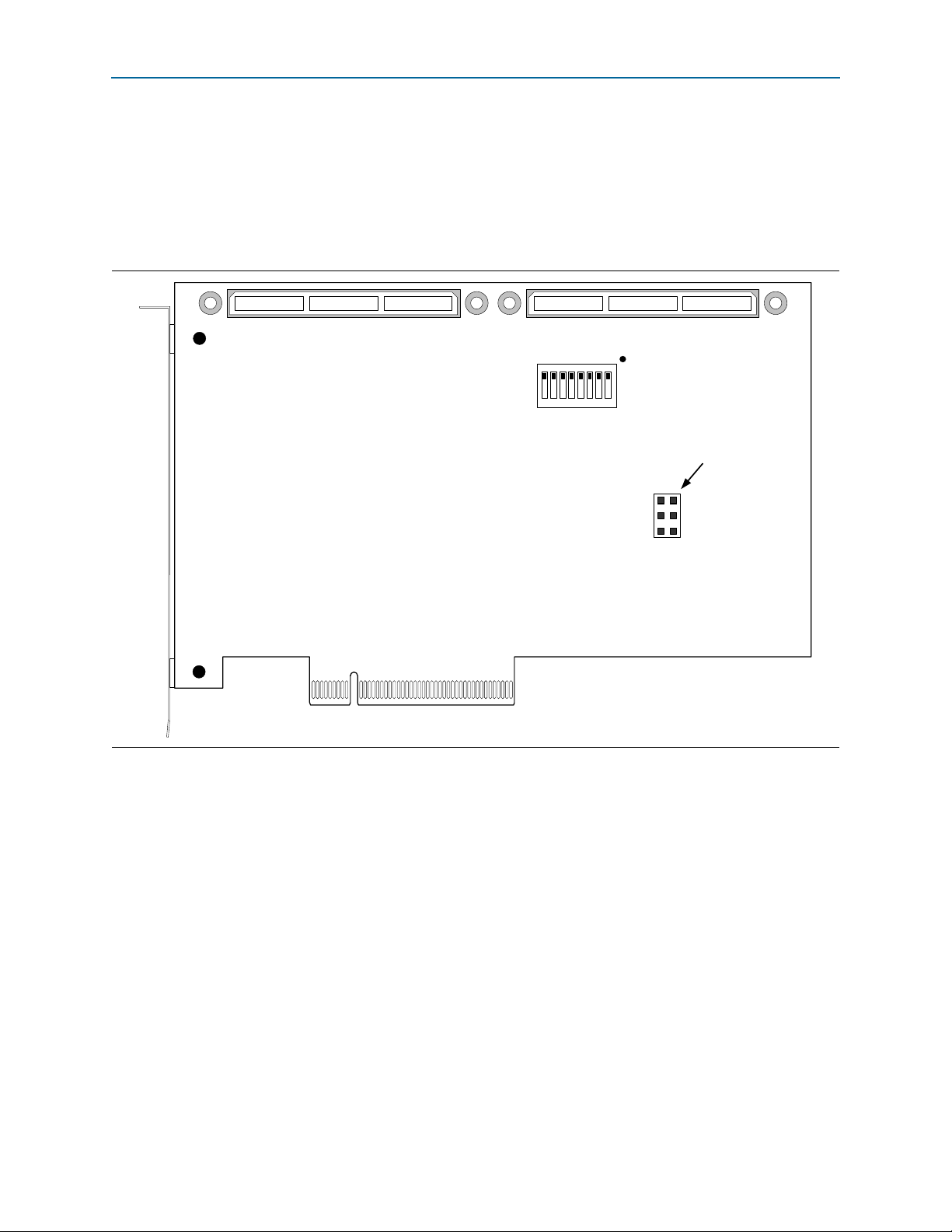
Factory Default Switch Settings
Factory Default Switch Settings
This section shows the factory switch settings for the Stratix V GX FPGA development
board.
Figure 4–1 shows the switch locations and the default position of each switch on the
top side of the board.
Figure 4–1. Switch Locations and Default Settings on the Board Top
Stratix V GX FPGA Development Kit July 2012 Altera Corporation
User Guide
 Loading...