

Page 1

Altera SoC Embedded Design Suite User
Guide
Subscribe
Send Feedback
ug-1137
2014.12.15
101 Innovation Drive
San Jose, CA 95134
www.altera.com
Page 2

TOC-2
Contents
Introduction to SoC Embedded Design Suite.................................................... 1-1
Installing the Altera SoC Embedded Design Suite.............................................2-1
Licensing..............................................................................................................3-1
Overview....................................................................................................................................................... 1-1
Device Tree Binary...........................................................................................................................1-2
Hardware and Software Development Roles........................................................................................... 1-3
Hardware – Software Development Flow.................................................................................................1-5
Installation Folders......................................................................................................................................2-1
Installing the SoC EDS................................................................................................................................2-1
Installing the ARM DS-5 Altera Edition Toolkit.....................................................................................2-2
Getting the License...................................................................................................................................... 3-1
Activating the License................................................................................................................................. 3-2
Getting Started Guides........................................................................................4-1
Getting Started with Board Setup..............................................................................................................4-1
External Connections......................................................................................................................4-1
Dual in-line package (DIP) Switch Settings.................................................................................4-2
Jumper Settings................................................................................................................................ 4-2
Getting Started with Running Linux.........................................................................................................4-2
Getting Started with Preloader...................................................................................................................4-3
Getting Started with GCC Bare-Metal Project Management................................................................ 4-6
Start Eclipse.......................................................................................................................................4-6
Create New Project.......................................................................................................................... 4-6
Set the Linker Script.........................................................................................................................4-9
Write Application Source Code...................................................................................................4-12
Build Application...........................................................................................................................4-15
Debug Application.........................................................................................................................4-17
Getting Started with ARM Compiler Bare-Metal Project Management............................................4-25
Start Eclipse.....................................................................................................................................4-25
Create a New Project.....................................................................................................................4-26
Create a Linker Script....................................................................................................................4-29
Set the Linker Script.......................................................................................................................4-34
Write Application Source Code...................................................................................................4-37
Build Application...........................................................................................................................4-40
Debug Application.........................................................................................................................4-42
Getting Started with Bare-Metal Debugging..........................................................................................4-51
Bare-Metal Debugging Sample Application Overview.............................................................4-51
Starting the Eclipse IDE................................................................................................................4-52
Altera Corporation
Page 3

TOC-3
Importing the Bare-Metal Debugging Sample Application.....................................................4-52
Compiling the Bare-Metal Debugging Sample Application....................................................4-54
Running the Bare-Metal Debugging Sample Application........................................................4-54
Getting Started with the Hardware Library........................................................................................... 4-58
Hardware Library Sample Application Overview.....................................................................4-58
Starting the Eclipse IDE................................................................................................................4-59
Importing the Hardware Library Sample Application............................................................. 4-59
Compiling the Hardware Library Sample Application.............................................................4-62
Running the Hardware Library Sample Application................................................................4-62
Getting Started with Peripheral Register Visibility...............................................................................4-67
Getting Started with Linux Kernel and Driver Debugging..................................................................4-72
Linux Kernel and Driver Debugging Prerequisites...................................................................4-72
Starting Eclipse with the Embedded Command Shell..............................................................4-73
Debugging the Kernel....................................................................................................................4-73
Getting Started with Linux Application Debugging.............................................................................4-78
Configuring Linux......................................................................................................................... 4-78
Starting Eclipse with the Embedded Command Shell..............................................................4-79
Importing the Linux Application Debugging Sample Application........................................ 4-79
Compiling the Linux Application Debugging Sample Application........................................4-82
Setting up Remote System Explorer............................................................................................4-82
Running the Linux Application Debugging Sample Application...........................................4-88
Getting Started with Tracing....................................................................................................................4-92
Getting Started with Cross Triggering....................................................................................................4-96
Cross-triggering Prerequisites......................................................................................................4-96
Enabling Cross-triggering on HPS..............................................................................................4-98
FPGA Triggering HPS Example................................................................................................ 4-100
Enabling Cross-triggering on FPGA.........................................................................................4-103
HPS Triggering FPGA Example................................................................................................ 4-104
ARM DS-5 Altera Edition................................................................................... 5-1
Starting Eclipse.............................................................................................................................................5-1
Bare-metal Project Management...............................................................................................................5-2
Bare-metal Project Management using Makefiles.......................................................................5-2
GCC-Based Bare-Metal Project Management.............................................................................5-5
ARM Compiler Bare-Metal Project Management.................................................................... 5-11
Debugging...................................................................................................................................................5-22
Accessing Debug Configurations................................................................................................ 5-22
Creating a New Debug Configuration........................................................................................5-23
Debug Configuration Options.....................................................................................................5-25
DTSL Options.................................................................................................................................5-34
Embedded Command Shell.................................................................................6-1
HPS Preloader User Guide..................................................................................7-1
HPS Configuration...................................................................................................................................... 7-1
Preloader Support Package Generator......................................................................................................7-2
Altera Corporation
Page 4

TOC-4
Hardware Handoff Files..................................................................................................................7-3
Using the Preloader Support Package Generator GUI...............................................................7-3
Preloader Support Package Files and Folders..............................................................................7-4
Command-Line Tools for the Preloader Support Package Generator.....................................7-5
BSP Settings...................................................................................................................................... 7-9
Preloader Compilation..............................................................................................................................7-15
Configuring FPGA from Preloader.........................................................................................................7-15
RBF File Stored in QSPI Flash Memory..................................................................................... 7-16
RBF File Stored on SD/MMC Card.............................................................................................7-16
Preloader Image Tool................................................................................................................................7-16
Operation of the Preloader Image Tool......................................................................................7-17
Tool Usage...................................................................................................................................... 7-18
Output Image Layout.................................................................................................................... 7-19
mkimage Tool.............................................................................................................................................7-20
mkimage Tool Options................................................................................................................. 7-21
mkimage Tool Image Creation.................................................................................................... 7-21
Hardware Library................................................................................................ 8-1
Feature Description..................................................................................................................................... 8-2
SoC Abstraction Layer (SoCAL)....................................................................................................8-2
Hardware Manager (HW Manager)..............................................................................................8-2
Hardware Library Reference Documentation..........................................................................................8-3
HPS Flash Programmer User Guide...................................................................9-1
HPS Flash Programmer Command-Line Utility.....................................................................................9-1
How the HPS Flash Programmer Works..................................................................................................9-1
Using the Flash Programmer from the Command Line........................................................................ 9-2
HPS Flash Programmer...................................................................................................................9-2
HPS Flash Programmer Command Line Examples....................................................................9-4
Supported Memory Devices.......................................................................................................................9-6
Bare-Metal Compiler.........................................................................................10-1
SD Card Boot Utility......................................................................................... 11-1
Usage Scenarios..........................................................................................................................................11-1
Tool Options...............................................................................................................................................11-2
Linux Software Development Tools..................................................................12-1
Linux Compiler..........................................................................................................................................12-1
SD Card Boot Utility................................................................................................................................. 12-2
Usage Scenarios..............................................................................................................................12-2
Tool Options...................................................................................................................................12-2
Device Tree Generator..............................................................................................................................12-4
Yocto Plugin............................................................................................................................................... 12-5
Altera Corporation
Page 5

TOC-5
Support and Feedback.......................................................................................13-1
Altera Corporation
Page 6

2014.12.15
www.altera.com
101 Innovation Drive, San Jose, CA 95134
Introduction to SoC Embedded Design Suite
1
ug-1137
The Altera® system on a chip (SoC) Embedded Design Suite (EDS) provides the tools needed to develop
embedded software for Altera's SoC devices.
The Altera SoC EDS is a comprehensive tool suite for embedded software development on Altera SoC
devices. The Altera SoC EDS contains development tools, utility programs, run-time software, and
application examples that enable firmware and application software development on the Altera SoC
hardware platform.
Overview
The Altera SoC EDS enables you to perform all required software development tasks targeting the Altera
SoCs, including:
• Board bring-up
• Device driver development
• Operating system (OS) porting
• Bare-metal application development and debugging
• OS- and Linux-based application development and debugging
• Debug systems running symmetric multiprocessing (SMP)
• Debug software targeting soft IP residing on the FPGA portion of the device
Subscribe
Send Feedback
©
2014 Altera Corporation. All rights reserved. ALTERA, ARRIA, CYCLONE, ENPIRION, MAX, MEGACORE, NIOS, QUARTUS and STRATIX words and logos are
trademarks of Altera Corporation and registered in the U.S. Patent and Trademark Office and in other countries. All other words and logos identified as
trademarks or service marks are the property of their respective holders as described at www.altera.com/common/legal.html. Altera warrants performance
of its semiconductor products to current specifications in accordance with Altera's standard warranty, but reserves the right to make changes to any
products and services at any time without notice. Altera assumes no responsibility or liability arising out of the application or use of any information,
product, or service described herein except as expressly agreed to in writing by Altera. Altera customers are advised to obtain the latest version of device
specifications before relying on any published information and before placing orders for products or services.
ISO
9001:2008
Registered
Page 7

1-2
Device Tree Binary
The major components of the SoC EDS include:
• ARM® Development Studio 5 (DS-5™) Altera Edition (AE) Toolkit
• Compiler tool chains:
• Bare-metal GNU Compiler Collection (GCC) tool chain from Mentor Graphics
®
• ARM Bare-metal compiler tool chain.
• Linux GCC compiler tool chain from Linaro
• Pre-built Linux package including:
• Linux kernel executable
• Linux kernel U-boot image
• Device tree blob
• Secure Digital (SD) card image
• Script to download Linux source code from the Git tree on the Rocketboards website
(www.rocketboards.org). The script downloads the sources corresponding to the pre-built Linux
package.
• SoC Hardware Library (HWLIB)
• Hardware-to-software interface utilities:
• Preloader generator
• Device tree generator
• Sample applications
• Golden Hardware Reference Design (GHRD) including:
ug-1137
2014.12.15
• FPGA hardware project
• FPGA hardware SOF file
• Precompiled preloader
• Embedded command shell allowing easy invocation of the included tools:
• SD Card Boot Utility
• Yocto Eclipse plugin
• Quartus® II Programmer and SignalTap II
The Linux package included in the SoC EDS is not an official release and is intended to be used
Note:
only as an example. Use the official Linux release described in the Golden System Reference Design
(GSRD) User Manual available on the Rocketboards website or a specific release from the Git trees
located on the Gitweb page of the Rocketboards website for development.
Note: The SoC EDS is tested only with the Linux release that comes with it. Newer Linux releases may
not be fully compatible with this release of SoC EDS.
Note: The Golden Hardware Reference Design (GHRD) included with the SoC EDS is not an official
release and is intended to be used only as an example. For development purposes, use the official
GHRD release described in the GSRD User Manual available on the Rocketboards website.
Related Information
RocketBoards Website
Device Tree Binary
There are two device tree binary (DTB) files delivered as part of the SoC EDS:
Altera Corporation
Introduction to SoC Embedded Design Suite
Send Feedback
Page 8
ug-1137
2014.12.15
• The socfpga_cyclone5.dtb file is a generic DTB file which does not have any dependency on soft IP.
FPGA programming and bridge releasing are not required before Linux starts running using this DTB.
This DTB file is intended for customers interested in bringing up a new board or just wanting to
simplify their boot flow until they get to the Linux prompt. If what is being developed or debugged
does not involve the FPGA, it is better to remove the FPGA complexities.
• The soc_system.dtb file is based on the GHRD design, which is part of the GSRD. Since the GHRD
does contain soft IPs, this DTB notifies Linux to load the soft IP drivers. Therefore, the FPGA needs to
be programmed and the bridges released before booting Linux.
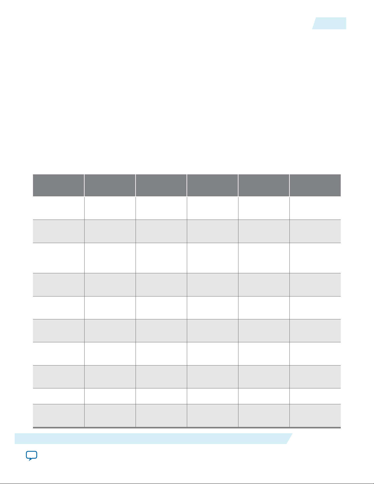
Hardware and Software Development Roles
Depending on your role in hardware or software development, you need a different subset of the SoC EDS
toolkit. The following table lists some typical engineering development roles and indicates which tools
each role typically requires.
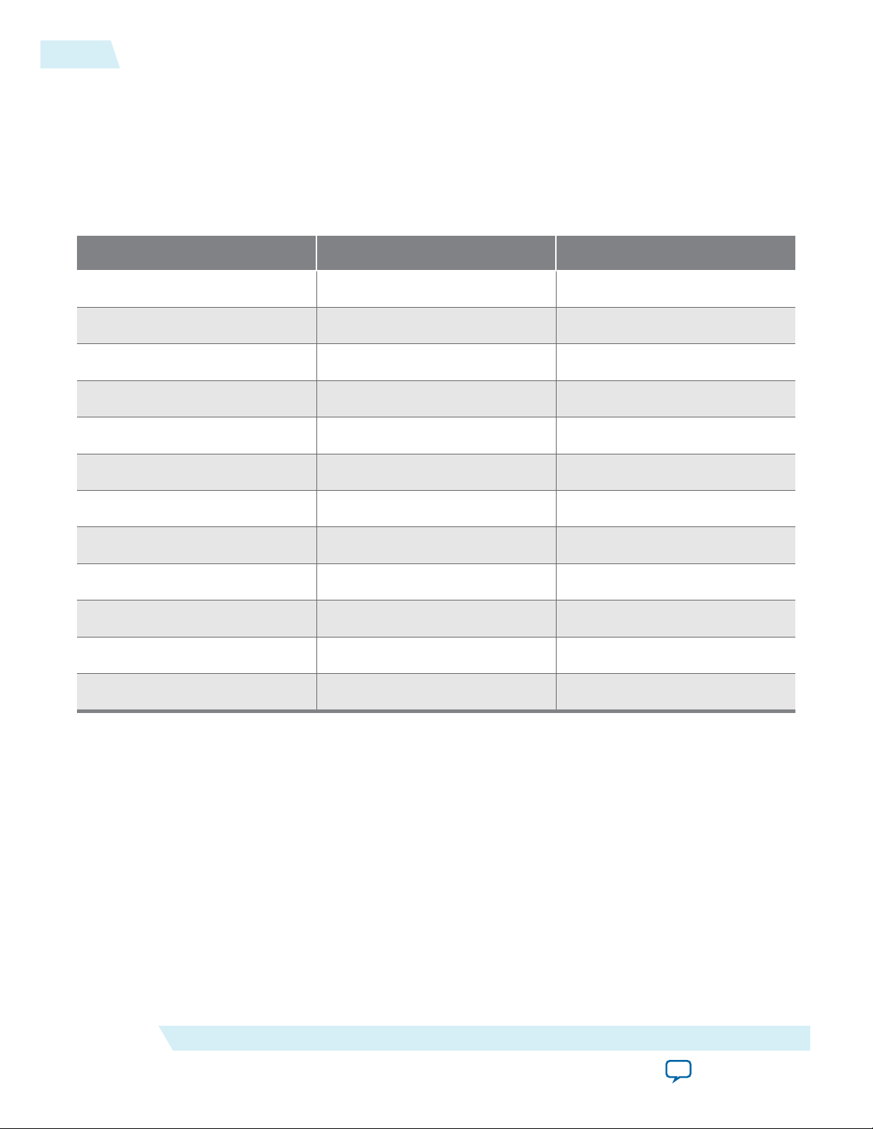
Table 1-1: Hardware and Software Development Roles
Hardware and Software Development Roles
1-3
Tool Hardware
Engineer
ARM DS-5
Debugging
ARM DS-5
Tracing
ARM DS-5
Cross
Triggering
Hardware
Libraries
Preloader
Generator
Flash
Programmer
Bare-Metal
Compiler
Bare-Metal
Developer
RTOS Developer Linux Kernel and
Driver Developer
Linux Application
Developer
√ √ √ √ √
√ √ √
√ √ √
√ √ √
√ √ √ √
√ √ √ √
√ √ √ √
Linux
√ √
Compiler
Yocto Plugin
Device Tree
√
Generator
Introduction to SoC Embedded Design Suite
Send Feedback
√ √
Altera Corporation
Page 9

1-4
Hardware and Software Development Roles
This table lists typical tool usage, but your actual requirements depend on your specific project and
organization.
Hardware Engineer
As a hardware engineer, you typically design the FPGA hardware in Qsys. You can use the debugger of
the ARM DS-5 Altera Edition to connect to the ARM cores and test the hardware. A convenient feature of
the DS-5 debugger is the soft IP register visibility, using Cortex Microcontroller Software Interface
Standard (CMSIS) System View Description (.svd) files. With this feature, you can easily read and modify
the soft IP registers from the ARM side.
As a hardware engineer, you may generate the Preloader for your hardware configuration. The Preloader
is a piece of software that configures the HPS component according to the hardware design.
As a hardware engineer, you may also perform the board bring-up. You can use the ARM DS-5 debugger
to verify that they can connect to the ARM and the board is working correctly.
These tasks require JTAG debugging, which is enabled only in the Subscription Edition. For more
information, see the Licensing section.
Bare-Metal and RTOS Developer
As either a bare-metal or a RTOS developer, you need JTAG debugging and low-level visibility into the
system.
ug-1137
2014.12.15
Use the bare-metal compiler to compile your code and the SoC Hardware Library to control the hardware
in a convenient and consistent way.
Use the Flash Programmer to program the flash memory on the target board.
These tasks require JTAG debugging, which is enabled only in the Subscription Edition. For more
information, see the Licensing section.
Linux Kernel and Driver Developer
As a Linux kernel or driver developer, you may use the same tools the RTOS developers use, because you
need low-level access and visibility into the system. However, you must use the Linux compiler instead of
the bare-metal compiler. You can use the Yocto plugin to manage the project and the device tree
generator to generate device trees.
These tasks require JTAG debugging, which is enabled only in the Subscription Edition. For more
information, see the Licensing section.
Linux Application Developer
As a Linux application developer, you write code that targets the Linux OS running on the board. Because
the OS provides drivers for all the hardware, you do not need low-level visibility over JTAG. DS-5 offers a
very detailed view of the OS, showing information such as which threads are running and which drivers
are loaded.
You can use the Yocto plugin to manage the application build.
These tasks do not require JTAG debugging. You can perform them both in the Web and Subscription
editions. For more information, see the Licensing section.
Related Information
Licensing on page 3-1
For more information about .svd files, refer to the Hardware - Software Development Flow section.
Altera Corporation
Introduction to SoC Embedded Design Suite
Send Feedback
Page 10
ug-1137
2014.12.15
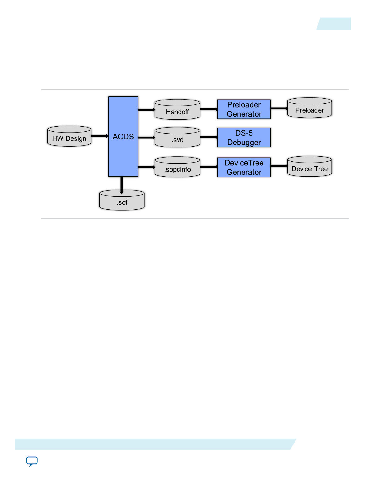
Hardware – Software Development Flow
The Altera hardware-to-software handoff utilities allow hardware and software teams to work independ‐
ently and follow their respective familiar design flows.
Figure 1-1: Altera Hardware-to-Software Handoff
Hardware – Software Development Flow
1-5
The following handoff files are created when the hardware project is compiled:
• Handoff folder – contains information about how the HPS component is configured, including things
like which peripherals are enabled, the pin MUXing and IOCSR settings, and memory parameters
• .svd file – contains descriptions of the HPS registers and of the soft IP registers on FPGA side
• .sopcinfo file – contains a description of the entire system
The handoff folder is used by the preloader generator to create the Preloader. For more information about
the handoff folder, refer to the HPS Preloader User Guide.
The .svd file contains the description of the registers of the HPS peripheral registers and registers for soft
IP components in the FPGA portion of the SoC. This file is used by the ARM DS-5 Debugger to allow
these registers to be inspected and modified by the user.
SOPC Information (.sopcinfo) file, containing a description of the entire system, is used by the Device
Tree Generator to create the Device Tree used by the Linux kernel. For more information, refer to the
Device Tree Generator chapter.
The soft IP register descriptions are not generated for all soft IP cores.
Note:
Related Information
• HPS Preloader User Guide on page 7-1
• Device Tree Generator
Introduction to SoC Embedded Design Suite
Send Feedback
Altera Corporation
Page 11

Installing the Altera SoC Embedded Design
www.altera.com
101 Innovation Drive, San Jose, CA 95134
2014.12.15
ug-1137
You must install the Altera SoC Embedded Design Suite (EDS) and the ARM Development Studio 5
(DS-5) Altera Edition (AE) Toolkit to run the SoC EDS on an Altera SoC hardware platform.
Subscribe
Installation Folders
The default installation folder for SoC EDS is:
• <SoC EDS installation directory>
• c:\altera\14.1\embedded on Windows
• ~/altera/14.1/embedded on Linux
The default installation folder for Quartus Programmer is:
• <Quartus installation directory>
• c:\altera\14.1\qprogrammer on Windows
• ~/altera/14.1/qprogrammer on Linux
Send Feedback
Suite
2
Note:
The installation directories are defined, as follows:
• <Altera installation directory> to denote the location where Altera tools are installed.
• <SoC EDS installation directory> to denote the location where SoC EDS is installed.
Installing the SoC EDS
Perform the following steps to install the SoC EDS Tool Suite in a Windows-based system:
1. Download the latest installation program from the SoC Embedded Design Suite page of the Altera
website.
2. Run the installer to open the Installing SoC Embedded Design Suite (EDS) dialog box, and click Next
to start the Setup Wizard.
3. Accept the license agreement, and click Next.
4. Accept the default installation directory or browse to another installation directory, and click Next.
Note: If you have previously installed the Quartus® II software, accept the default SoC EDS installation
directory to allow the Quartus II software and the SoC EDS Tool Suite to operate together.
©
2014 Altera Corporation. All rights reserved. ALTERA, ARRIA, CYCLONE, ENPIRION, MAX, MEGACORE, NIOS, QUARTUS and STRATIX words and logos are
trademarks of Altera Corporation and registered in the U.S. Patent and Trademark Office and in other countries. All other words and logos identified as
trademarks or service marks are the property of their respective holders as described at www.altera.com/common/legal.html. Altera warrants performance
of its semiconductor products to current specifications in accordance with Altera's standard warranty, but reserves the right to make changes to any
products and services at any time without notice. Altera assumes no responsibility or liability arising out of the application or use of any information,
product, or service described herein except as expressly agreed to in writing by Altera. Altera customers are advised to obtain the latest version of device
specifications before relying on any published information and before placing orders for products or services.
ISO
9001:2008
Registered
Page 12

2-2
Installing the ARM DS-5 Altera Edition Toolkit
5. Select All the components to be installed, and click Next. The installer displays a summary of the
installation.
6. Click Next to start the installation process. The installer displays a separate dialog box with the
installation progress of the component installation.
7. When the installation is complete, turn on Launch DS-5 Installation to start the ARM DS-5 installa‐
tion, and click Finish.
Note: On some Linux-based machines, you can install the SoC EDS with a setup GUI similar to the
Windows-based setup GUI. Because of the variety of Linux distributions and package require‐
ments, not all Linux machines can use the setup GUI. If the GUI is not available, use an equivalent
command-line process. Download the Linux installation program from the SoC Embedded
Design Suite page on the Altera website.
Installing the ARM DS-5 Altera Edition Toolkit
For the last step of the SoC EDS installation process, start the ARM DS-5 AE Toolkit installer.
Note: Make sure you have the proper setting to access the internet.
1. When the Welcome message is displayed, click Next.
2. Accept the license agreement and click Next.
3. Accept the default installation path, to ensure proper interoperability between SoC EDS and
ARM DS-5 AE, and click Next.
4. Click Install to start the installation process. The progress bar is displayed.
5. When a driver installation window appears, click Next.
6. Accept the driver installation and click Install.
7. After successful installation, click Finish. ARM DS-5 AE installation is complete.
8. Click Finish.
ug-1137
2014.12.15
Altera Corporation
Installing the Altera SoC Embedded Design Suite
Send Feedback
Page 13
2014.12.15
www.altera.com
101 Innovation Drive, San Jose, CA 95134
Licensing
3
ug-1137
Subscribe
Send Feedback
The SoC EDS is available with three different licensing options:
• Subscription edition
• Free web edition
• 30-day evaluation of subscription edition
The only tool impacted by the selected licensing option is the ARM DS-5 Altera Edition. All the other
tools offer the same level of features in all licensing options; for example, the preloader generator and the
bare-metal compiler offer the same features no matter which licensing option is used.
The main difference between the licensing options depends on which types of debugging scenarios are
enabled:
Licensing Option Debugging Scenarios Enabled
Web edition • Linux application debugging over ethernet
Subscription edition
30-day evaluation of the subscription edition
• JTAG-based Bare-Metal Debugging
• JTAG-based Linux Kernel and Driver
Debugging
• Linux Application Debugging over Ethernet
Getting the License
Depending on the licensing option, it is necessary to follow the steps detailed for each option to obtain the
license.
Subscription Edition - If you have purchased the SoC EDS Subscription Edition, then you have already
received an ARM license serial number. This is a 15-digit alphanumeric string with two dashes in
between. You will need to use this number to activate your license in DS-5, as shown in the Activating the
License section.
Free Web Edition - For the free SoC EDS Web Edition, you will be able to use DS-5 perpetually to debug
Linux applications over an Ethernet connection. Get your ARM license activation code from the SoC
Embedded Design Suite download page on the Altera website (http://dl.altera.com/soceds) and then
activate your license in DS-5, as shown in the Activating the License section.
30-Day Evaluation of Subscription Edition - If you want to evaluate the SoC EDS Subscription Edition,
you can get a 30-Day Evaluation activation code from the SoC Embedded Design Suite download page on
©
2014 Altera Corporation. All rights reserved. ALTERA, ARRIA, CYCLONE, ENPIRION, MAX, MEGACORE, NIOS, QUARTUS and STRATIX words and logos are
trademarks of Altera Corporation and registered in the U.S. Patent and Trademark Office and in other countries. All other words and logos identified as
trademarks or service marks are the property of their respective holders as described at www.altera.com/common/legal.html. Altera warrants performance
of its semiconductor products to current specifications in accordance with Altera's standard warranty, but reserves the right to make changes to any
products and services at any time without notice. Altera assumes no responsibility or liability arising out of the application or use of any information,
product, or service described herein except as expressly agreed to in writing by Altera. Altera customers are advised to obtain the latest version of device
specifications before relying on any published information and before placing orders for products or services.
ISO
9001:2008
Registered
Page 14
3-2
Activating the License
the Altera website (http://dl.altera.com/soceds) and then activate your license in DS-5, as shown in the
Activating the License section.
Related Information
• SoC EDS Download Page
• Activating the License on page 3-2
Activating the License
This section presents the steps required for activating the license in DS-5 Altera Edition by using the serial
license number or activation code that were mentioned in the "Getting the License" section.
Note:
An active user account is required to activate the DS-5 Altera Edition license. If you do not have an
active user account, it can be created on the ARM Self-Service page available on the ARM website
(silver.arm.com).
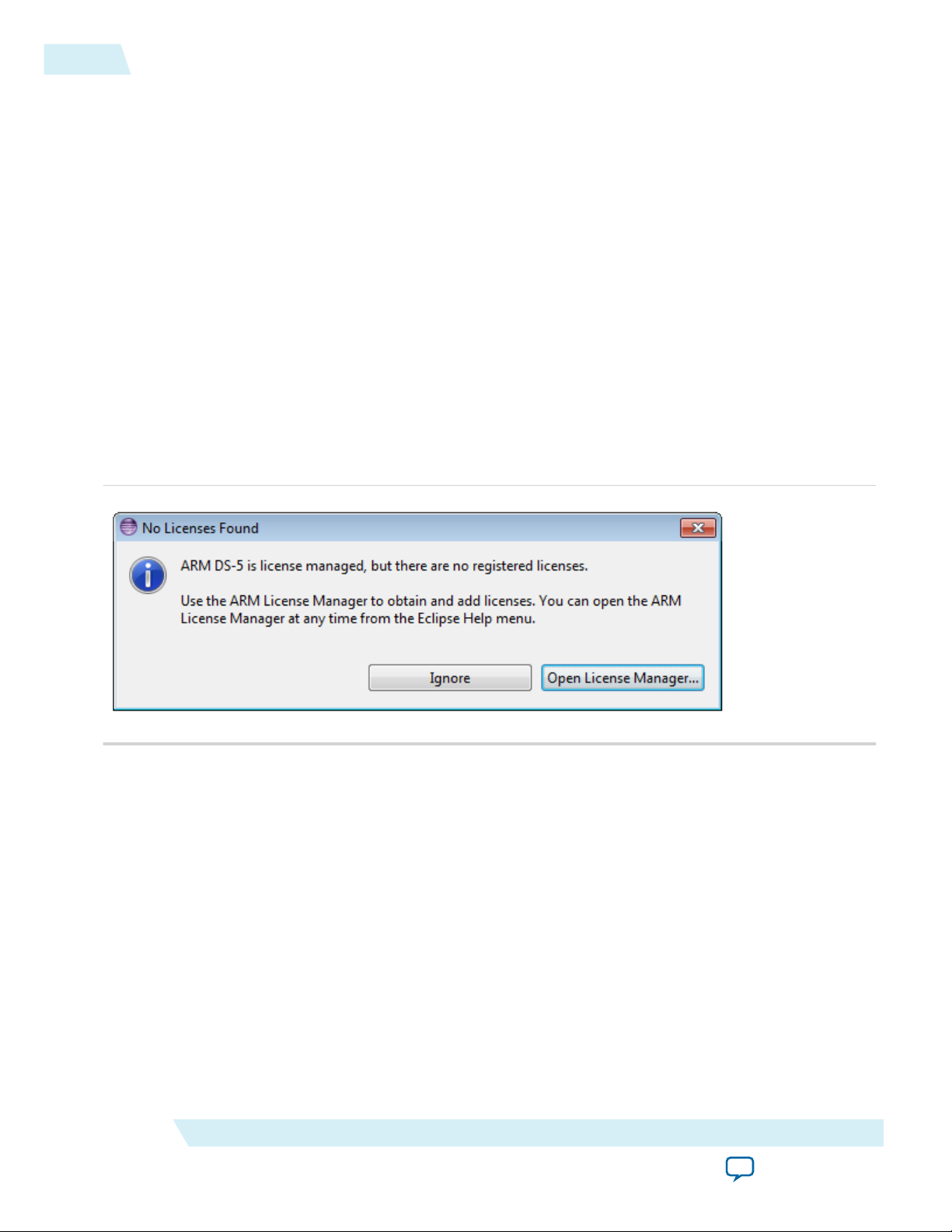
The first time the Eclipse IDE from the ARM DS-5 is run, it notifies you that it requires a license. Click
1.
the Open License Manager button.
Figure 3-1: No License Found
ug-1137
2014.12.15
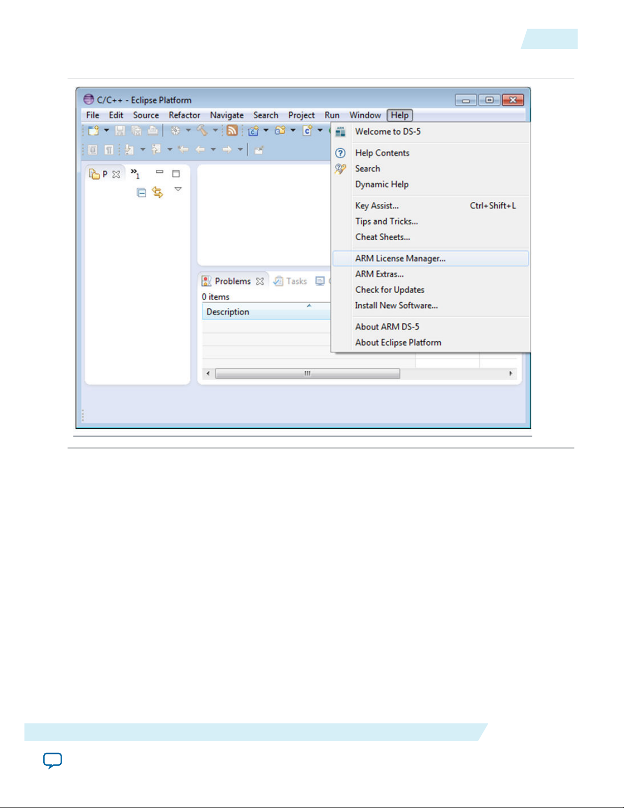
2. If at any time it is required to change the license, select Help > ARM License Manager to open the
Altera Corporation
License Manager.
Licensing
Send Feedback
Page 15
ug-1137
2014.12.15
Figure 3-2: Accessing ARM License Manager
Activating the License
3-3
Licensing
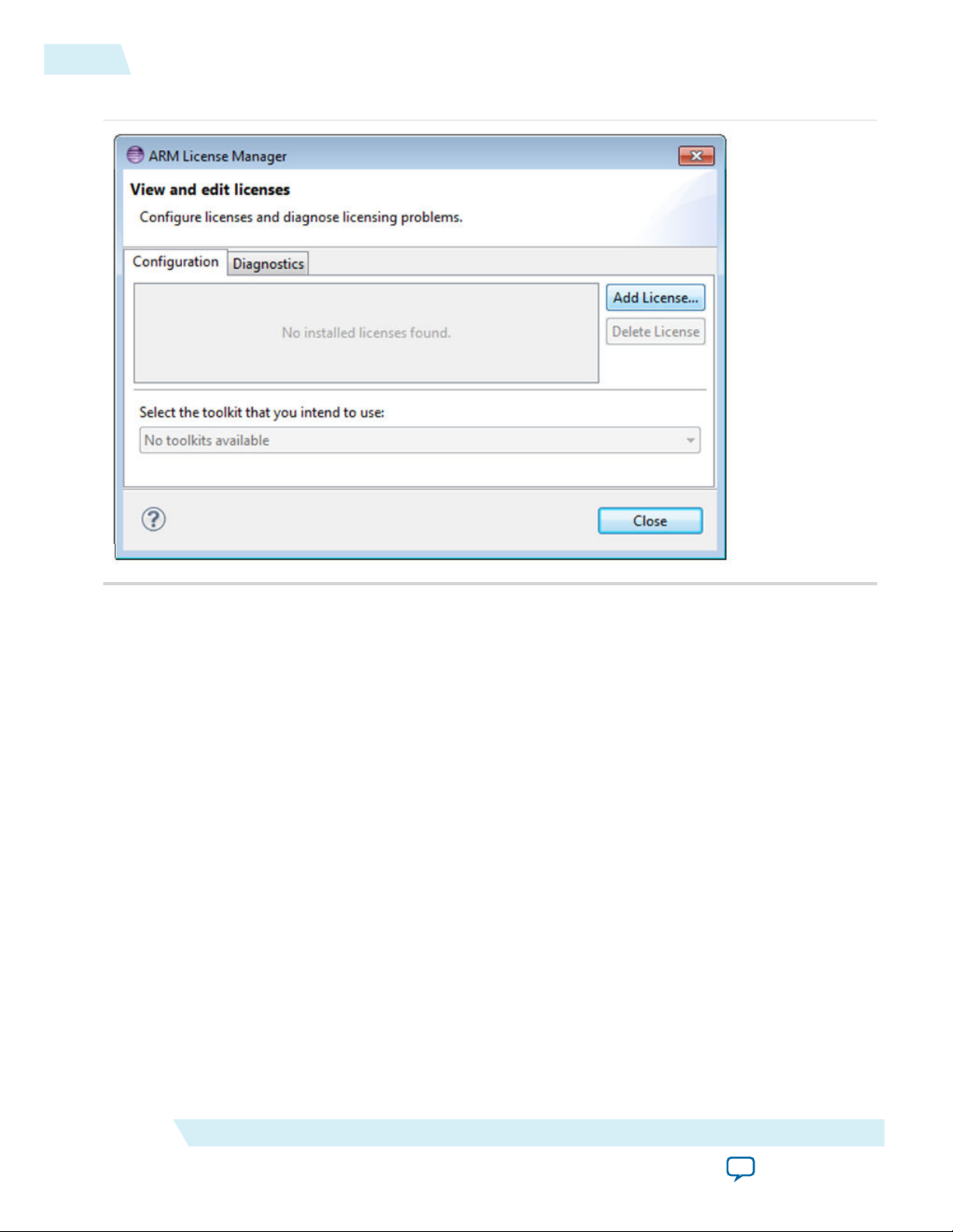
3. The License Manager - View and edit licenses dialog box opens and shows that a license is not
available. Click the Add License button.
Altera Corporation
Send Feedback
Page 16
3-4
Activating the License
Figure 3-3: ARM License Manager
ug-1137
2014.12.15
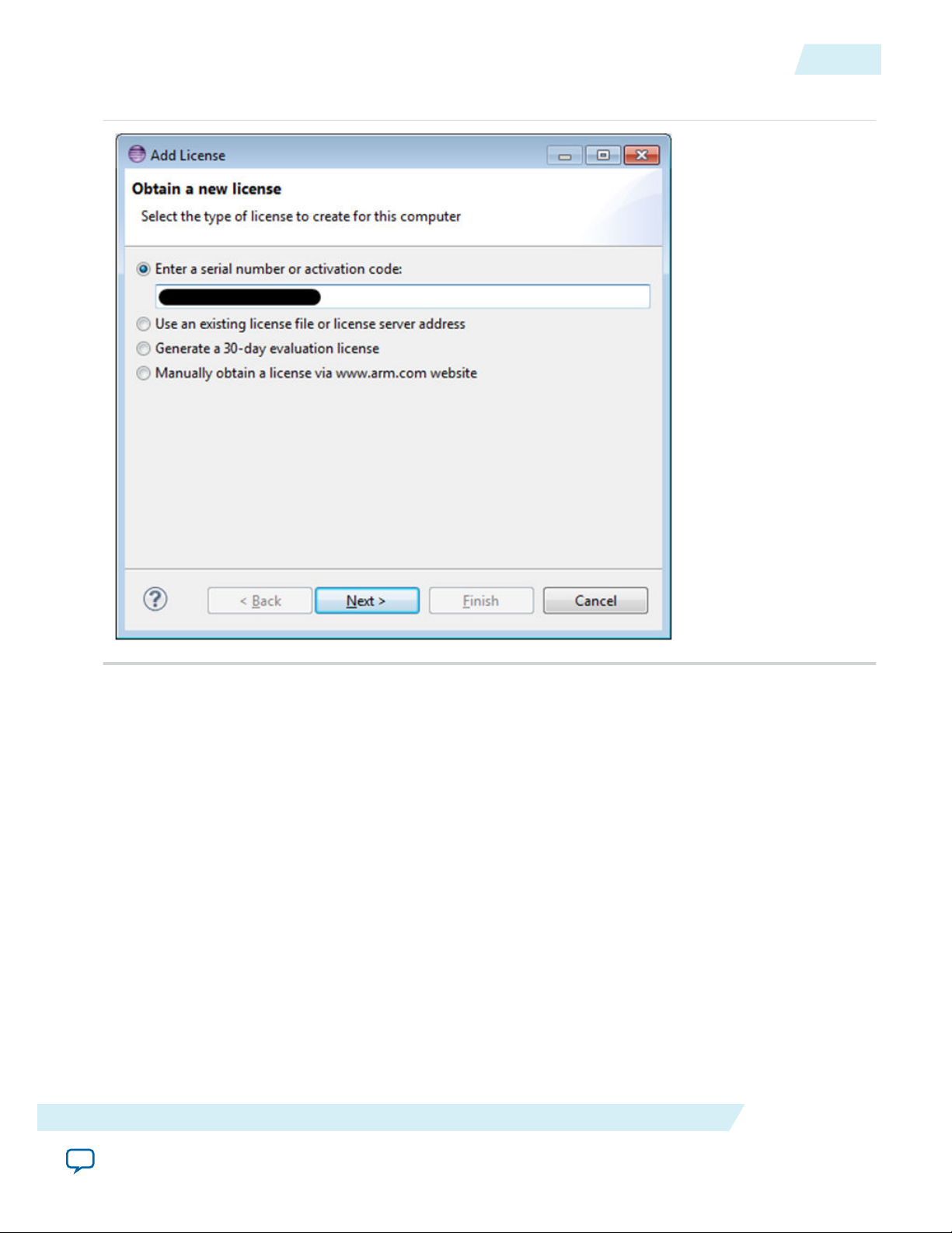
4. In the Add License - Obtain a new licenses dialog box, select the type of license to enter. In this
example, select the radio button, “Enter a serial number or activation code to obtain a license” to
enter the choices listed, below. When done, click Enter.
a. ARM License Number for Subscription Edition.
b. ARM License Activation Code for Web Edition and 30-Day Evaluation.
Altera Corporation
Licensing
Send Feedback
Page 17
ug-1137
2014.12.15
Figure 3-4: Add License - Obtain a New License
Activating the License
3-5
Licensing
5. Click Next.
6. In the Add License - Choose Host ID dialog box, select the Host ID (Network Adapter MAC address)
to tie the license to. If there are more than one option, select the one you desire to lock the license to,
and click Next.
Altera Corporation
Send Feedback
Page 18

3-6
Activating the License
Figure 3-5: Add License - Choose host ID
ug-1137
2014.12.15
7. In the Add License - Developer account details dialog box, enter an ARM developer (Silver) account.
If you do not have an account, it can be created easily by clicking the provided link. After entering the
account information, click Finish.
Figure 3-6: Add License - Developer Account Details
Altera Corporation
Note:
The License Manager needs to be able to connect to the Internet in order to activate the license.
If you do not have an Internet connection, you will need to write down your Ethernet MAC
Licensing
Send Feedback
Page 19
ug-1137
2014.12.15
Activating the License
address and generate the license directly from the ARM Self-Service web page on the ARM
website (silver.arm.com), then select the "Already have a license" option in the License Manger.
Note: Only the Subscription Edition, with an associated license number can be activated this way. The
Web Edition and Evaluation edition are based on activation codes, and these codes cannot be
used on the ARM Self-Service web page on the ARM website (silver.arm.com). They need to be
entered directly in the License Manager; which means an Internet connection is a requirement
for licensing.
The ARM License Manager uses the Eclipse settings to connect to the Internet. The default Eclipse
settings is to use the system-wide configuration for accessing the Internet. In case the License Manager
cannot connect to the Internet, you can try to change the Proxy settings by going to Window >
Preferences > General > Network Connections. Ensure that "HTTPS" proxy entry is configured and
enabled.
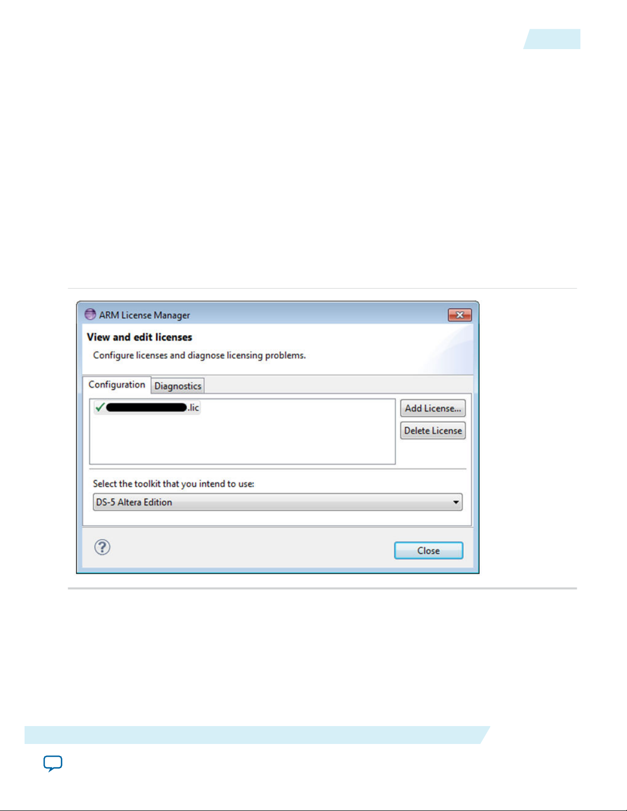
8. After a few moments, the ARM DS-5 will activate the license and display it in the License Manager.
Click Close.
Figure 3-7: ARM License Manager
3-7
Licensing
Related Information
• ARM website
• Getting the License on page 3-1
Altera Corporation
Send Feedback
Page 20

2014.12.15
www.altera.com
101 Innovation Drive, San Jose, CA 95134
Getting Started Guides
4
ug-1137
Subscribe
Send Feedback
This chapter presents a series of getting started guides aimed at enabling you to quickly get accustomed to
doing the basic SoC software development tasks.
The following items are covered:
• Preloader
• Bare-Metal debugging
• SoC Hardware library (HWLIB)
• Peripheral register visibility
• Linux application debugging
• Linux Kernel and driver debugging
• Tracing
• Cross Triggering
The following additional topics are covered to support the above scenarios:
• Board setup – needed for all the scenarios
• Running Linux – needed for the scenarios that use Linux
The guides presented in this chapter are intedned to be run on a Cyclone V SoC Development board.
Getting Started with Board Setup
This section presents the necessary Altera Cyclone V Development Kit board settings in order to run
Linux and the Getting Started examples.
External Connections
• External 19V power supply connected to J22 – DC Input
• Mini USB cable connected from host PC to J37 – Altera USB Blaster II connector. This is used for
connecting the host PC to the board for debugging purposes.
• Mini USB cable connected from host PC to J8 – UART USB connector. This is used for exporting the
UART interface to the host PC.
• Ethernet cable from connector J3 to local network. This is used if Linux network connectivity is
desired.
©
2014 Altera Corporation. All rights reserved. ALTERA, ARRIA, CYCLONE, ENPIRION, MAX, MEGACORE, NIOS, QUARTUS and STRATIX words and logos are
trademarks of Altera Corporation and registered in the U.S. Patent and Trademark Office and in other countries. All other words and logos identified as
trademarks or service marks are the property of their respective holders as described at www.altera.com/common/legal.html. Altera warrants performance
of its semiconductor products to current specifications in accordance with Altera's standard warranty, but reserves the right to make changes to any
products and services at any time without notice. Altera assumes no responsibility or liability arising out of the application or use of any information,
product, or service described herein except as expressly agreed to in writing by Altera. Altera customers are advised to obtain the latest version of device
specifications before relying on any published information and before placing orders for products or services.
ISO
9001:2008
Registered
Page 21
4-2
Dual in-line package (DIP) Switch Settings
Dual in-line package (DIP) Switch Settings
• SW1 = all switches OFF
• SW2 = all switches OFF
• SW3 = ON-OFF-OFF-OFF-ON-ON. This selects the proper FPGA configuration option (MSEL).
• SW4 = OFF-OFF-ON-ON. This selects both HPS and FPGA to be in the JTAG scan chain.
Jumper Settings
Number Name Setting
J5 9V Open
J6 JTAG_HPS_SEL Shorted
J8 JTAG_SEL Shorted
J9 UART Signals Open
J13 OSC1_CLK_SEL Shorted
ug-1137
2014.12.15
J15 JTAG_MIC_SEL Open
J26 CLKSEL0 2-3 Shorted
J27 CLKSEL1 2-3 Shorted
J28 BOOTSEL0 1-2 Shorted
J29 BOOTSEL1 2-3 Shorted
J30 BOOTSEL2 1-2 Shorted
J31 SPI_I2C Open
Getting Started with Running Linux
This section presents how to run the provided Linux image on the board, to be able to run the Getting
Started sections related to Linux.
The provided Linux image is an example only; use the latest version from the Rocketboards website
Note:
for your development.
Altera Corporation
Getting Started Guides
Send Feedback
Page 22
ug-1137
2014.12.15
Getting Started with Preloader
The steps are:
1. Setup the board as described in Board Setup section.
2. Extract the SD card image from the archive <SoC EDS installation directory>\embeddedsw\socfpga\
prebuilt_images\sd_card_linux_boot_image.tar.gz. The file is named sd_card_linux_boot_image.img.
The command tar -xzf<filename> can be used from Embedded Command Shell to achieve this.
3. Write the SD card image to a micro SD card using the free tool Win32DiskImager from the
Sourceforge Projects website (sourceforge.net) on Windows or the dd utility on Linux.
4. Power up the board using the PWR switch.
5. Connect a serial terminal from the host PC to the serial port corresponding to the UART USB
connection; and use 115,200 baud, no parity, 1 stop bit, no flow control settings.
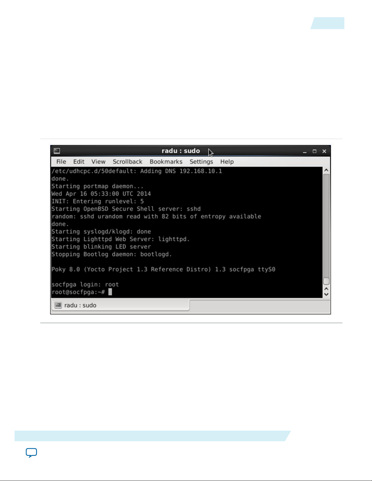
6. After successful boot, Linux will ask for the login name. Enter root and click Enter.
Figure 4-1: Linux Booted
4-3
Related Information
• Rocket Boards
For more information about the latest Linux version, refer to the Rocketboards website.
• Sourceforge Projects
To obtain the free tool - Win32DiskImager, refer to the Projects section of the Sourceforge website.
Getting Started with Preloader
This section presents an example of how to generate and compile the Preloader for the Cyclone V SoC
Golden Hardware Reference Design (GHRD) that is provided with SoC EDS.
Getting Started Guides
Send Feedback
Altera Corporation
Page 23
4-4
Getting Started with Preloader
ug-1137
2014.12.15
The Preloader is an essential tool for SoC software. It performs the low-level initialization, brings up
SDRAM memory, loads the next boot stage from flash to SDRAM and executes it.
The Preloader is already delivered as part of the GHRD in the <SoC EDS installation directory>/examples/
hardware/cv_soc_devkit_ghrd/software/preloader folder.
In this example, you will re-create the Preloader in the folder <SoC EDS installation directory>/examples/
hardware/cv_soc_devkit_ghrd/software/spl_bsp.
The screen snapshots presented in this section were created using the Windows version of SoC EDS, but
the example can be run in a very similar way on a Linux host PC.
The steps to create the Preloader are:
1. Start an Embedded Command Shell by executing <SoC EDS installation directory>\Embedded_Command_
Shell.bat.
2.
Run the command, bsp-editor. The BSP Editor dialog box appears.
Note: The tool that generates a preloader support package is the BSP Editor, also used to generate
BSPs for other Altera products.
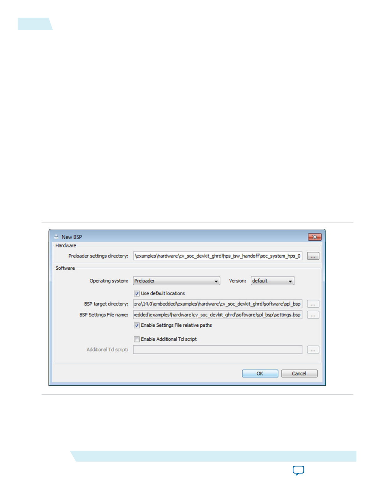
3. Select File > New BSP.The New BSP dialog opens.
4.
Click the “…” button to browse for the Preloader settings directory in the New BSP dialog box.
5. Browse <SoCEDS folder>\examples\hardware\cv_soc_devkit_ghrd\hps_isw_handoff\soc_system_hps_0 for the
hardware handoff folder. The rest of the Preloader settings are populated automatically.
Figure 4-2: Populated Options in the New BSP Window
6. Click OK to close the New BSP dialog box. This will populate the BSP Editor dialog box with the
Altera Corporation
default settings.
Getting Started Guides
Send Feedback
Page 24
ug-1137
2014.12.15
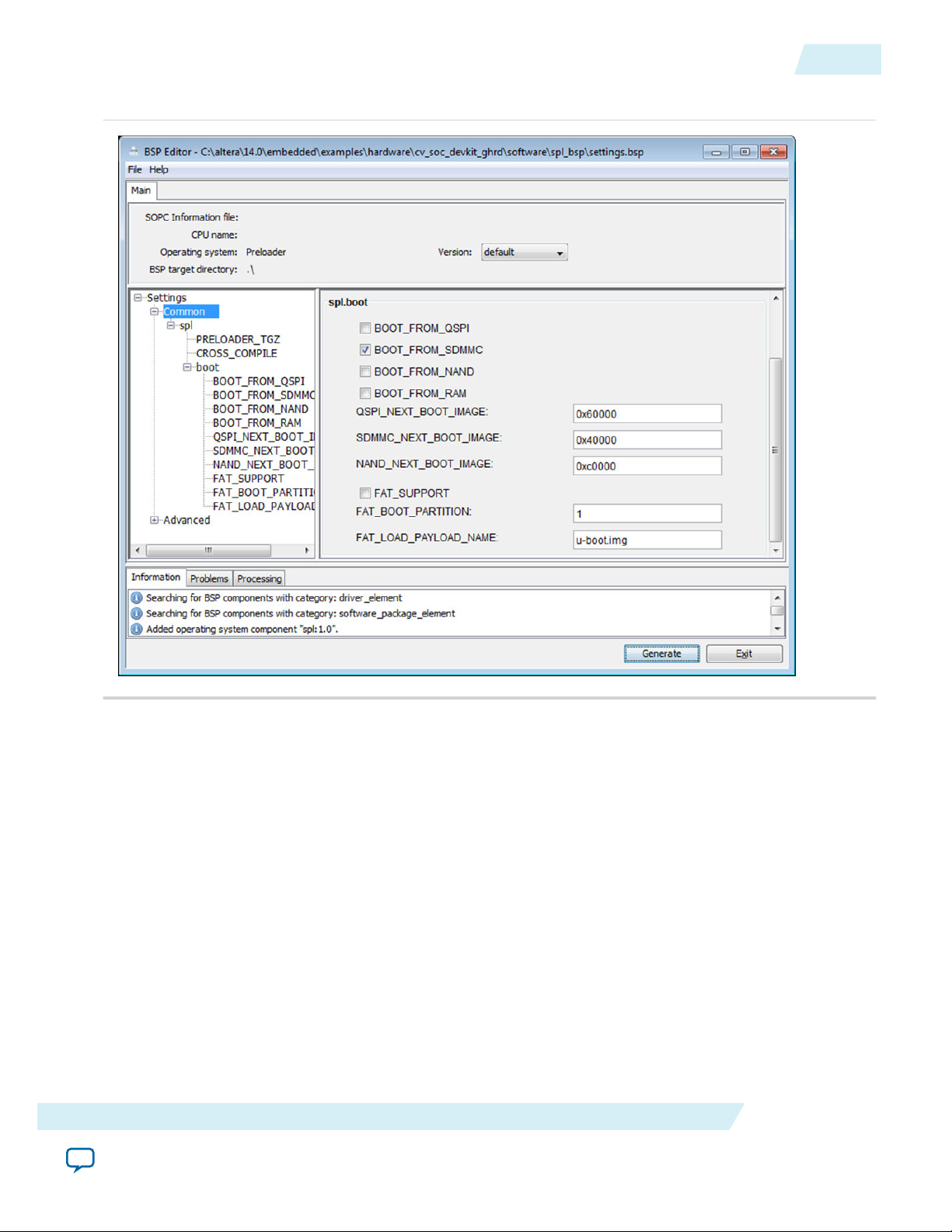
Figure 4-3: Default Options in the BSP Editor window
Getting Started with Preloader
4-5
7. Click Generate in the BSP Editor dialog box to generate the Preloader files.
8. Click Exit in the BSP Editor dialog box to exit the application.
9. In the Embedded Command Shell, execute the following commands:
• cd <SoC EDS installation directory>\examples\hardware\cv_soc_devkit_ghrd\software\spl_bsp
• make
10.The Preloader is ready to be used in the above folder. Some of the more relevant files that are created:
• preloader-mkpimage.bin – Preloader with the proper header to be loaded by BootROM
• uboot-socfpga \ spl \ u-boot- spl – Preloader ELF file, to be used for debugging purposes
• uboot-socfpga \tools\mkimage.exe – Utility to add the header needed by the Preloader to
Related Information
• Preloader
For more information about the Preloader, refer to the Preloader section.
Getting Started Guides
Send Feedback
recognize the next boot stage
Altera Corporation
Page 25
4-6
Getting Started with GCC Bare-Metal Project Management
• Cyclone V Device Handbook: Booting and Configuration
For more information about Booting and Configuration with regards to Preloader, refer to the Booting
and Configuration appendix in volume 3 of the Cyclone V Device Handbook.
• Arria V Device Handbook: Booting and Configuration
For more information about Booting and Configuration with regards to Preloader, refer to the Booting
and Configuration appendix in volume 3 of the Arria V Device Handbook.
Getting Started with GCC Bare-Metal Project Management
This section presents a complete bare-metal example demonstrating the GCC bare-metal project
management features of the ARM DS-5 Altera Edition.
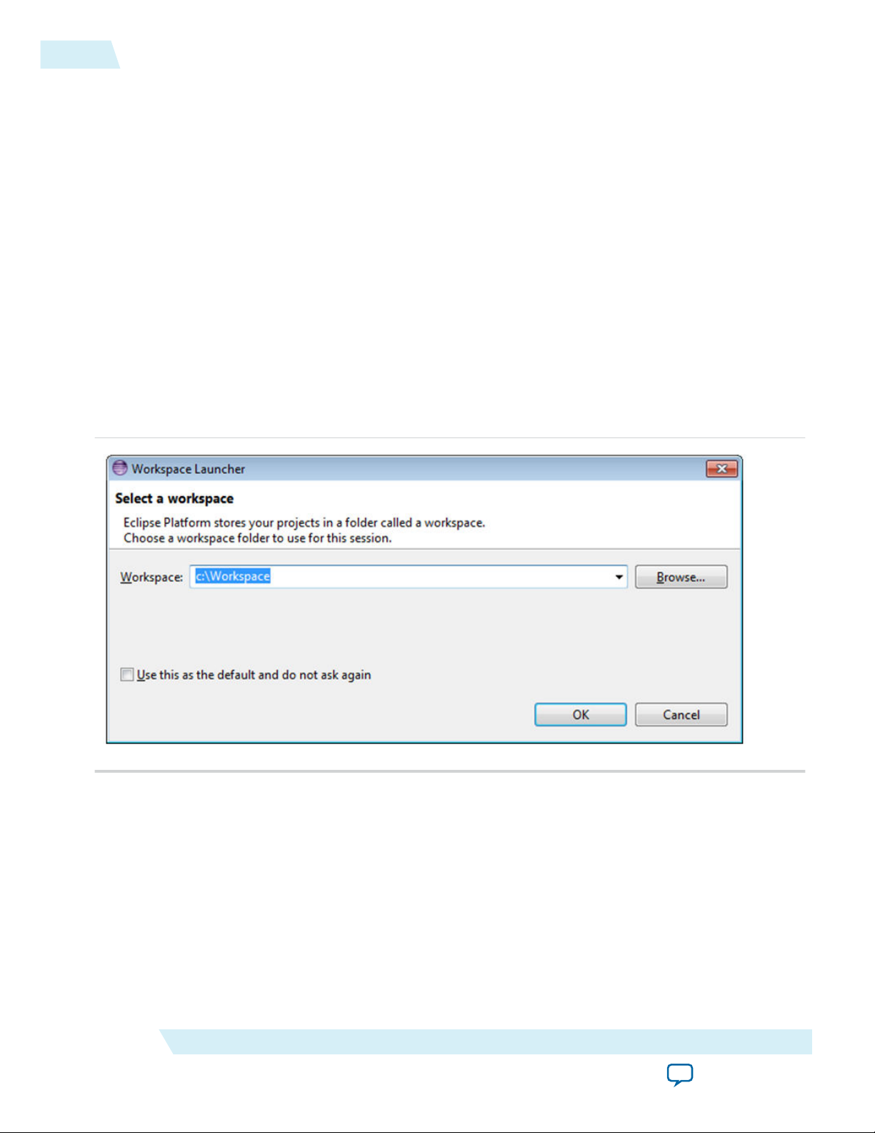
Start Eclipse
1. Start Eclipse
The Workspace Launcher dialog box appears.
Figure 4-4: Select a Workspace
ug-1137
2014.12.15
2.
Select a new workspace to use. For example, you can enter c:\Workspace and click OK.
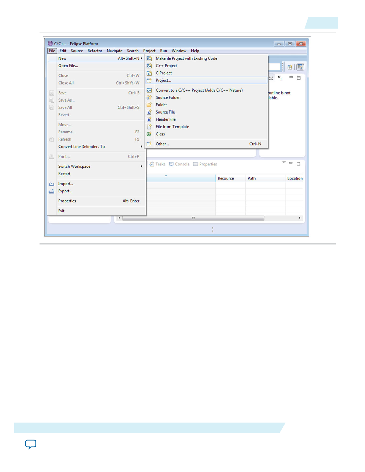
Create New Project
1. Go to File > New > Project...
Altera Corporation
Getting Started Guides
Send Feedback
Page 26
ug-1137
2014.12.15
Create New Project
4-7
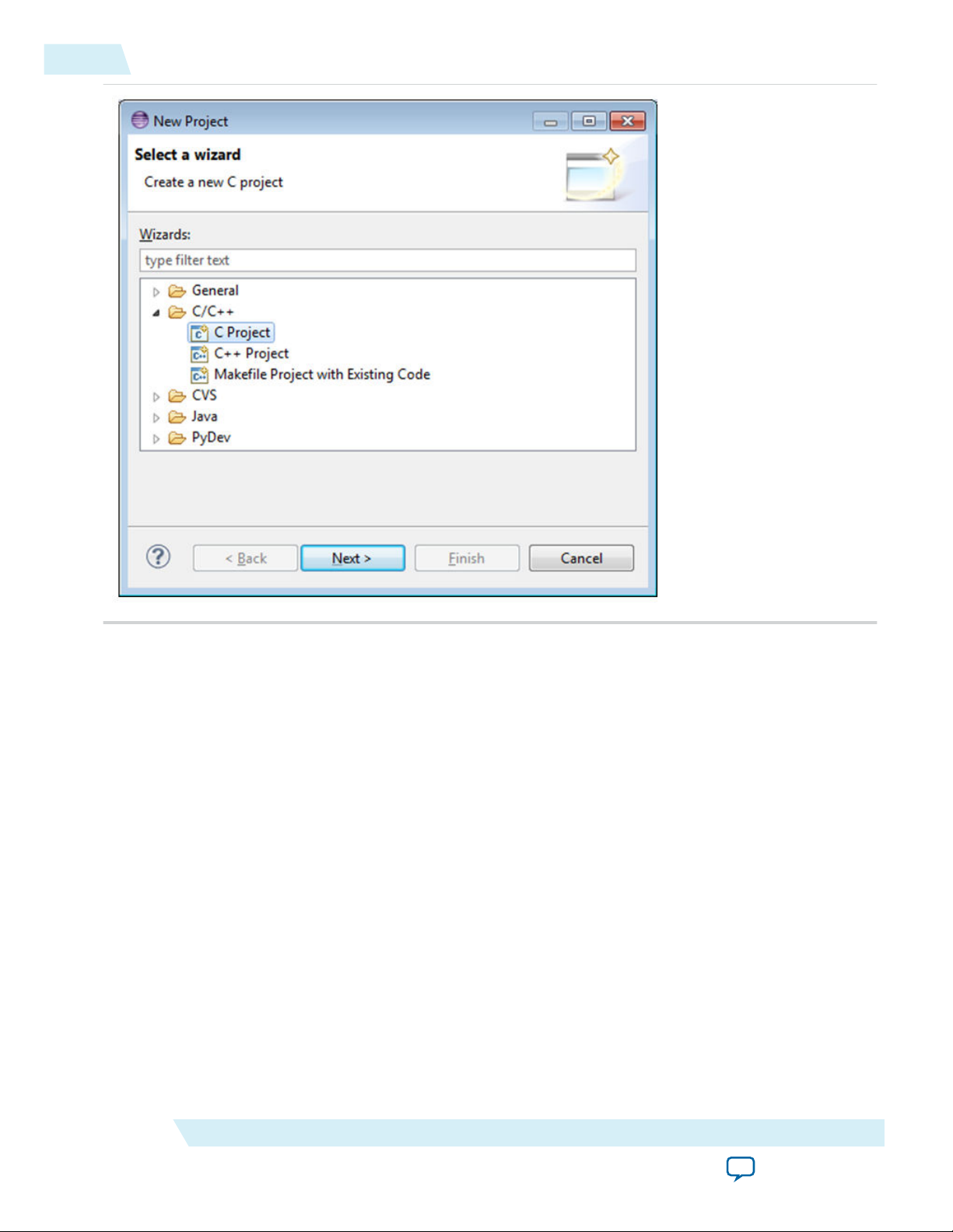
2. Select C/C++ > C Project and click Next.
Getting Started Guides
Send Feedback
Altera Corporation
Page 27
4-8
Create New Project
ug-1137
2014.12.15
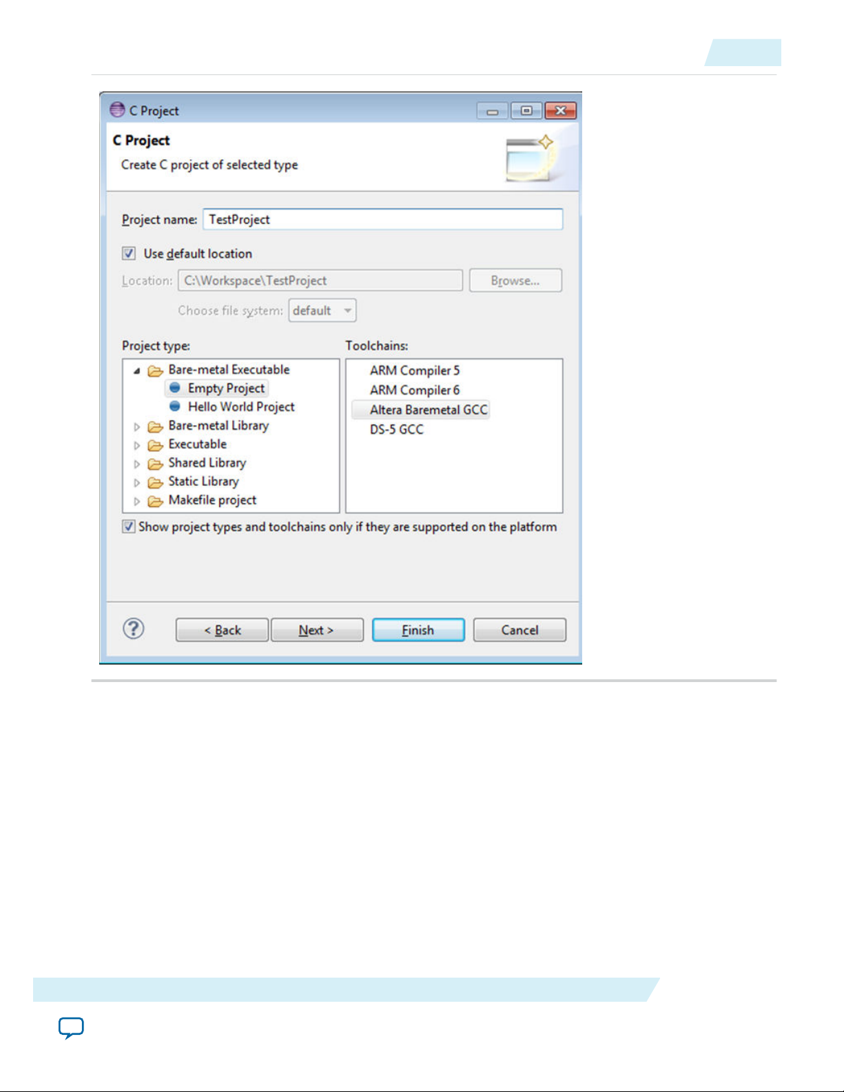
3.
Edit Project Name to be TestProject, select Project Type to be Bare-metal Executable > Empty
Project, and select Toolchains to be Altera Baremetal GCC. Click Finish.
Altera Corporation
Getting Started Guides
Send Feedback
Page 28
ug-1137
2014.12.15
Set the Linker Script
4-9
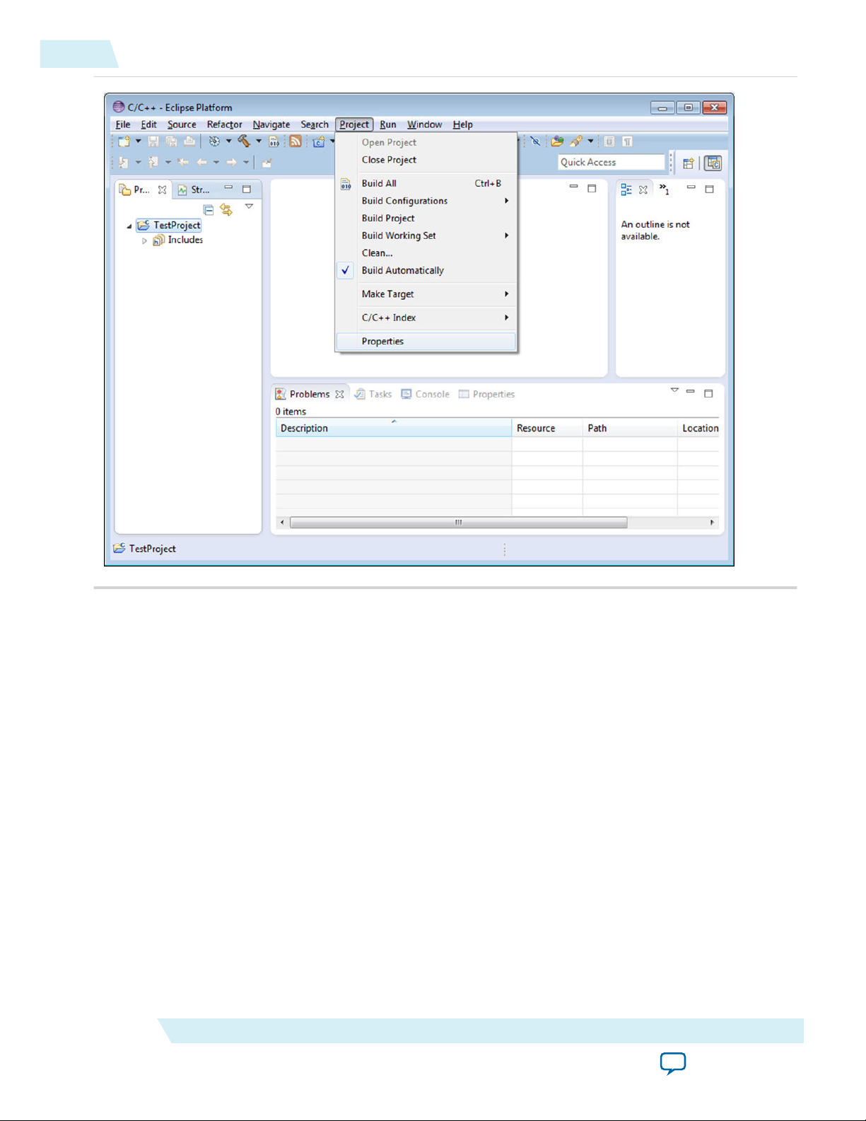
Set the Linker Script
1. Go to Project > Properties
Getting Started Guides
Send Feedback
Altera Corporation
Page 29
4-10
Set the Linker Script
ug-1137
2014.12.15
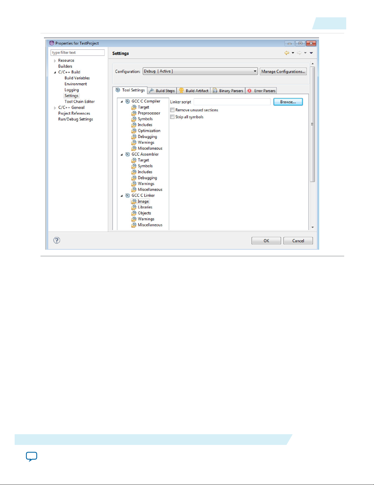
2. Go to C/C++ Build > Settings > GCC Linker > Image and then click Linker Script.
Altera Corporation
Getting Started Guides
Send Feedback
Page 30
ug-1137
2014.12.15
Set the Linker Script
4-11
3. Browse to <SoC EDS installation directory>\host_tools\mentor\gnu\arm\baremetal\arm-altera-eabi\lib\
cycloneV-dk-oc-ram-hosted.ld, select cycloneV-dk-oc-ram-hosted.ld, and click on the Open
button.
This will instruct the Linker to use a linker script that targets the 64 KB Internal RAM and also to use
semihosting operations.
Getting Started Guides
Send Feedback
Altera Corporation
Page 31

4-12
Write Application Source Code
ug-1137
2014.12.15
4. Click OK to close the Project Properties window.
Write Application Source Code
1. Go to File > New > Source File
Altera Corporation
Getting Started Guides
Send Feedback
Page 32

ug-1137
2014.12.15
Write Application Source Code
4-13
2.
Edit the filename in Source File to be test.c and click Finish.
Getting Started Guides
Send Feedback
Altera Corporation
Page 33

4-14
Write Application Source Code
3.
Edit the test.c file to contain the text shown in the following image.
ug-1137
2014.12.15
Note:
The __auto_semihosting symbol is a convenient way to let Debugger know that the current
executable image requires semihosting services.
Altera Corporation
Getting Started Guides
Send Feedback
Page 34

ug-1137
2014.12.15
Build Application
4-15
Build Application
1. Build the application by going to Project > Build Project.
Getting Started Guides
Altera Corporation
Send Feedback
Page 35

4-16
Build Application
ug-1137
2014.12.15
2. After the project is built, the Console shows the commands and the Project shows the created
TestProject.axf executable.
Altera Corporation
Getting Started Guides
Send Feedback
Page 36

ug-1137
2014.12.15
Debug Application
4-17
Debug Application
1. Setup board.
2. Go to Run > Debug Configurations
Getting Started Guides
Altera Corporation
Send Feedback
Page 37

4-18
Debug Application
ug-1137
2014.12.15
3. Right-click DS-5 Debugger and click New.
Altera Corporation
Getting Started Guides
Send Feedback
Page 38

ug-1137
2014.12.15
Debug Application
4-19
4. Select target to be Altera > Cyclone V SoC (Dual Core) > Bare Metal Debug > Debug Cortex-A9_0
and Target Connection to be USB-Blaster.
Getting Started Guides
Send Feedback
Altera Corporation
Page 39

4-20
Debug Application
ug-1137
2014.12.15
5. Click the Connection > Browse Button to select the connection to the target board.
6. Select the desired target and click Select.
Altera Corporation
Getting Started Guides
Send Feedback
Page 40

ug-1137
2014.12.15
Debug Application
4-21
7. Go to Files tab > Target Configuration > Application on host to download and click the Workspace
button to browse for the executable in the current Workspace:
8. Browse to the executable and click OK.
Getting Started Guides
Send Feedback
Altera Corporation
Page 41

4-22
Debug Application
ug-1137
2014.12.15
9. Click the Debug button to download the application and start the debug session.
Altera Corporation
Getting Started Guides
Send Feedback
Page 42

ug-1137
2014.12.15
Debug Application
4-23
10.When Eclipse asks you if you want to switch to Debug perspective, accept by clicking Yes.
11.Application will be downloaded and stopped at entry to main function:
Getting Started Guides
Altera Corporation
Send Feedback
Page 43

4-24
Debug Application
ug-1137
2014.12.15
12.Click the Continue button or press F8. The application runs to completion and exits. The Application
console shows the message printed by application.
Altera Corporation
Getting Started Guides
Send Feedback
Page 44

ug-1137
2014.12.15
Getting Started with ARM Compiler Bare-Metal Project Management
4-25
Getting Started with ARM Compiler Bare-Metal Project Management
This section presents a complete bare-metal example demonstrating the ARM Compiler bare-metal
project management features of the ARM DS-5 Altera Edition.
Start Eclipse
1. Start Eclipse.
2. Select a new workspace to use, for example c:\Workspace and press OK.
Getting Started Guides
Altera Corporation
Send Feedback
Page 45

4-26
Create a New Project
Figure 4-5: Select a Workspace
ug-1137
2014.12.15
Create a New Project
1. Go to File > New > Project...
Altera Corporation
Getting Started Guides
Send Feedback
Page 46

ug-1137
2014.12.15
Figure 4-6: New Project
Create a New Project
4-27
2. Select C/C++ > C Project and click Next.
Getting Started Guides
Altera Corporation
Send Feedback
Page 47

4-28
Create a New Project
Figure 4-7: Create a New C Project
ug-1137
2014.12.15
3.
Altera Corporation
Edit Project Name to be TestProject. Select Project Type to be Executable > Empty Project; then
Toolchains to be "ARM Compiler 5 (DS-5 built-in); then click Finish.
Getting Started Guides
Send Feedback
Page 48

ug-1137
2014.12.15
Figure 4-8: Create C Project
Create a Linker Script
4-29
Create a Linker Script
1. Go to File > New > Other....
Getting Started Guides
Send Feedback
Altera Corporation
Page 49

4-30
Create a Linker Script
ug-1137
2014.12.15
2. Select Scatter File Editor > Scatter File and press Next.
Altera Corporation
Getting Started Guides
Send Feedback
Page 50

ug-1137
2014.12.15
Figure 4-9: Create a Scatter File
Create a Linker Script
4-31
3.
Select the Test Project, edit the file name to be scatter.scat and click Finish.
Getting Started Guides
Send Feedback
Altera Corporation
Page 51

4-32
Create a Linker Script
Figure 4-10: Scatter File Resource
ug-1137
2014.12.15
4. Edit the file "scatter.scat" to contain the following:
Altera Corporation
Getting Started Guides
Send Feedback
Page 52

ug-1137
2014.12.15
Figure 4-11: Contents of "scatter.scat"
Create a Linker Script
4-33
The above linker script instructs the linker on how to link the application:
• Defines OCRAM base address (0xFFFF0000) and size (0x10000)
• Loads all application sections in the OCRAM
• Allocates a maximum of 16K (0x4000) for stack an heap
5. If desired, click on the "Regions/Section" tab and you will see a graphical view of the linker script.
Getting Started Guides
Send Feedback
Altera Corporation
Page 53

4-34
Set the Linker Script
Figure 4-12: Graphical View of the Linker Script
ug-1137
2014.12.15
Set the Linker Script
1. Go to Project > Properties.
Altera Corporation
Getting Started Guides
Send Feedback
Page 54

ug-1137
2014.12.15
Figure 4-13: Test Project Properties
Set the Linker Script
4-35
2. Go to C/C++ Build > Settings > ARM Linker 5 > Image Layout and then click Browse:
Getting Started Guides
Send Feedback
Altera Corporation
Page 55

4-36
Set the Linker Script
Figure 4-14: Settings
ug-1137
2014.12.15
3. Select the newly created file "scatter.scat" and click Open.
Altera Corporation
Getting Started Guides
Send Feedback
Page 56

ug-1137
2014.12.15
Figure 4-15: Opening the Newly Created File
Write Application Source Code
4-37
4. Click OK to close the Project Properties window.
Write Application Source Code
1. Go to File > New > Source File.
Getting Started Guides
Send Feedback
Altera Corporation
Page 57

4-38
Write Application Source Code
Figure 4-16: New Source File
ug-1137
2014.12.15
2. Edit the file name to be "test.c" and click Finish.
Altera Corporation
Getting Started Guides
Send Feedback
Page 58

ug-1137
2014.12.15
Figure 4-17: New Source File
Write Application Source Code
4-39
3. Edit the "test.c" file to contain the text shown in the following image:
Getting Started Guides
Send Feedback
Altera Corporation
Page 59

4-40
Build Application
Figure 4-18: Text for Test .c
ug-1137
2014.12.15
Build Application
1. Build the application by going to Project > Build Project.
Altera Corporation
Getting Started Guides
Send Feedback
Page 60

ug-1137
2014.12.15
Figure 4-19: Build Project
Build Application
4-41
2. The project is built. The console shows the commands, and the project shows the "TestProject.axf"
executable that was created.
Getting Started Guides
Send Feedback
Altera Corporation
Page 61

4-42
Debug Application
Figure 4-20: Console and Project Views Created
ug-1137
2014.12.15
Debug Application
1. Setup board.
2. Go to Run > Debug Configurations
Altera Corporation
Getting Started Guides
Send Feedback
Page 62

ug-1137
2014.12.15
Figure 4-21: Debug Configurations
Debug Application
4-43
3. Right-click DS-5 Debugger and click New.
Getting Started Guides
Send Feedback
Altera Corporation
Page 63

4-44
Debug Application
Figure 4-22: New DS-5 Debugger
ug-1137
2014.12.15
4. Select the "Target" to be Altera > Cyclone V SoC (Dual Core) > Bare Metal Debug > Debug Cortex-
Altera Corporation
A9_0 and "Target Connection" to be USB-Blaster.
Getting Started Guides
Send Feedback
Page 64

ug-1137
2014.12.15
Figure 4-23: Debug Configuration - Connection Tab
Debug Application
4-45
5. Click the Connection > Browse button to select the connection to the target board.
6. Select the desired target and click Select.
Getting Started Guides
Altera Corporation
Send Feedback
Page 65

4-46
Debug Application
Figure 4-24: Target Connection
ug-1137
2014.12.15
7. Go to Files tab > Target Configuration > Application on the host to download and click the
Workspace buton to browse for the executable in the current workspace:
Altera Corporation
Getting Started Guides
Send Feedback
Page 66

ug-1137
2014.12.15
Figure 4-25: Target Configuration
Debug Application
4-47
8. Browse to the executable and click OK.
Getting Started Guides
Altera Corporation
Send Feedback
Page 67

4-48
Debug Application
Figure 4-26: Open "TestProject.axf"
ug-1137
2014.12.15
9. Click the Debug button to download the application and start the debug session.
Altera Corporation
Getting Started Guides
Send Feedback
Page 68

ug-1137
2014.12.15
Figure 4-27: Debug Session Started
Debug Application
4-49
10.Eclipse will ask whether to switch to the "Debug" perspective. Accept by clicking Yes.
Figure 4-28: Confirm Perspective Switch
11.The application will be downloaded and stopped at entry to main function:
Getting Started Guides
Altera Corporation
Send Feedback
Page 69

4-50
Debug Application
Figure 4-29: DS-5 Debug Window
ug-1137
2014.12.15
12.Click the Continue button or press F8. The application will run to completion and exit. The applica‐
tion console will show the message printed by the application.
Altera Corporation
Getting Started Guides
Send Feedback
Page 70

ug-1137
2014.12.15
Figure 4-30: Application Console
Getting Started with Bare-Metal Debugging
4-51
Getting Started with Bare-Metal Debugging
The ARM DS-5 Altera Edition provides very powerful bare metal debugging capabilities.
This section presents running the ARM DS-5 Altera Edition for the first time, importing, compiling and
running the Hello World bare-metal example application provided as part of SoC EDS.
Sample Application Overview
Related Information
• ARM DS-5 Altera Edition on page 5-1
For more information, refer to the ARM DS-5 Altera Edition section.
• Online ARM DS-5 Documentation
The ARM DS-5 Altera Edition reference material can be accessed online on the documentation page of
the ARM website (www.arm.com); and from Eclipse by navigating to Help > Help Contents > ARM
DS-5 Documentation.
Bare-Metal Debugging Sample Application Overview
Getting Started Guides
Altera Corporation
Send Feedback
Page 71

4-52
Starting the Eclipse IDE
The provided sample application prints a “Hello” message on the debugger console, by using semihosting.
This way no pins are used and all communication happens through JTAG.
The application is located in the 64 KB On-Chip RAM, and therefore does not require the SDRAM
memory on the board to be configured.
This application can run on any board supporting the SoC device because of its simplicity, and it does not
require pins or external resources to be configured.
Note: Make sure that Linux (or another OS) is not running on the board prior to doing this example. An
OS can interfere with the feature of downloading and debugging bare-metal applications.
Note: The screen snapshots and commands presented in this section were created using the Windows
version of SoC EDS, but the example can be run in a very similar way on a Linux host PC.
Starting the Eclipse IDE
1. Select Start Menu > Programs > ARM DS-5 > Eclipse for DS-5 to start Eclipse. Alternatively, you can
run eclipse command from the Embedded Command Shell.
2. The Eclipse tool, part of ARM DS-5 AE, prompts for the workspace folder to be used. Use the
suggested folder and click OK.
3. The ARM DS-5 AE "Welcome" screen appears. It is instructive, and can be used to access documenta‐
tion, tutorials and videos.
4. Select Window > Open Perspective > DS-5 Debug to open the Workbench. Alternatively, you can
Click on the link Go to the Workbench located under the list of "DS-5 Resources".
ug-1137
2014.12.15
Importing the Bare-Metal Debugging Sample Application
1. In Eclipse, select File > Import. The Import dialog box displays.
2. In the Import dialog box, select General > Existing Projects into Workspace and click Next. This will open
the Import Projects dialog box.
Altera Corporation
Getting Started Guides
Send Feedback
Page 72

ug-1137
2014.12.15
Figure 4-31: Import Existing Project
Importing the Bare-Metal Debugging Sample Application
4-53
3. In the Import Projects dialog box, select the Select Archive File option.
4. Click Browse, then navigate to <SoC EDS installation directory>\embedded\examples\software\, select the
file Altera-SoCFPGA-HelloWorld-Baremetal-GNU.tar.gz and click Open.
5. Click Finish. The project is imported. The project files are displayed in the Project Explorer panel.
The following files are part of the project:
Table 4-1: Project Files
File Name Description
hello.c Sample application source code
Altera-SoCFPGA-HelloWorld-Baremetal-GNU-
Debug.launch
Launcher file used to run or debug the sample
application from within Eclipse
altera-socfpga-hosted.ld Linker script
semihost_setup.ds Debugger script use to load the sample application
makefile Makefile used to compile the sample application
Getting Started Guides
Send Feedback
Altera Corporation
Page 73

4-54
Compiling the Bare-Metal Debugging Sample Application
Compiling the Bare-Metal Debugging Sample Application
The sample application is compiled using the Mentor bare-metal GCC tool chain invoked by the
Makefile.
1. To compile the application, select the project in Project Explorer.
2. Select Project > Build Project.
Figure 4-32: Project Compiled
ug-1137
2014.12.15
3. The project compiles and the Project Explorer shows the newly created hello.axf executable file as
shown in the above figure. The Console dialog box shows the commands and responses that were
executed.
Running the Bare-Metal Debugging Sample Application
Before running the sample application, perform the following setup:
• Setup the board as described in Getting Started with Board Setup
• Connect mini USB cable from DevKit board connector J37 to PC
• Connect 19V power supply to the DevKit
• Turn on the board using the PWR switch
1. Select Run > Debug Configurations.. to access the launch configurations. The sample project comes
with a pre-configured launcher that allows the application to be run on the board.
2. In the Debug Configurations dialog box, on the left panel, select DS-5 Debugger > Altera-SoCFPGA-
HelloWorld-Baremetal-Debug.
Altera Corporation
Getting Started Guides
Send Feedback
Page 74

ug-1137
2014.12.15
The Target is already pre-configured to be Altera > Cyclone VSoC > Bare Metal Debug > Debug Cortex-A9_0
via Altera USB-Blaster.
3. Click Browse to select the USB Blaster connection.
Figure 4-33: Debug Configuration
Running the Bare-Metal Debugging Sample Application
4-55
4. In the Select Debug Hardware dialog box, select the desired USB Blaster and click OK.
Getting Started Guides
Send Feedback
Altera Corporation
Page 75

4-56
Running the Bare-Metal Debugging Sample Application
Figure 4-34: Select Debug Hardware
ug-1137
2014.12.15
5. Click the Debug button from the bottom of the Debug Configurations dialog box.
6. Eclipse ask whether to switch to Debug Perspective. Click Yes to accept it.
The debugger downloads the application on the board through JTAG, enables semi-hosting using the
provided script, and runs the application until the PC reaches the main function.
At this stage, all the debugging features of DS-5 can be used: viewing and editing registers and
variables, looking at the disassembly code.
Altera Corporation
Getting Started Guides
Send Feedback
Page 76

ug-1137
2014.12.15
Figure 4-35: Program Downloaded
Running the Bare-Metal Debugging Sample Application
4-57
7. Click Continue green button (or press F8) to run the application. It displays the hello message in the
Application Console.
Getting Started Guides
Send Feedback
Altera Corporation
Page 77

4-58
Getting Started with the Hardware Library
Figure 4-36: Debugging Session window
ug-1137
2014.12.15
8. Click Disconnect from Target button to close the debugging session.
Getting Started with the Hardware Library
The SoC Hardware Libraries example program is part of the Altera
You can run the sample program on a Cyclone V SoC development kit board.
The example program demonstrates using the Hardware Library to programmatically configure the
FPGA and exercise soft IP control from the hard processor system (HPS).
Hardware Library Sample Application Overview
The Bare Metal sample application uses the HWLIB API to:
• Programmatically configure the FPGA from the HPS
• Initialize and bring up the Advanced eXtensible Interface (AXI) bridge interfaces between the HPS and
the FPGA
• Exercise the FPGA soft IP parallel I/O (PIO) core from the HPS to toggle the development board LEDs
The sample application uses the development kit Golden System Reference Design (GSRD) FPGA
configuration. The sample application uses the following files:
• FPGA configuration SRAM Object File (.sof)
• Preloader executable file for proper initialization of the GSRD HPS component
®
SoC Embedded Design Suite (EDS).
Altera Corporation
Getting Started Guides
Send Feedback
Page 78

ug-1137
2014.12.15
Starting the Eclipse IDE
4-59
The sample application is built with a makefile that performs the following steps:
1. Copies Hardware Libraries source code from installation folder to the current project folder.
2. Compiles the example C source code files with the GNU Compiler Collection (GCC) tool chain from
Mentor Graphics
3. Copies the .sof file from the GSRD folder
4. Converts the .sof file to a compressed Raw Binary File (.rbf) format with the quartus_cpf utility
available in the Altera Complete Design Suite or the Quartus II software programmer.
5. Converts the .rbf to an equivalent Executable and Linking Format File (.elf) object file with the GCC
objcopy utility.
6. Links the example program and the FPGA configuration resource object files into the HWLIB example
executable file.
A debugger script performs the following steps to help execute the sample application:
1. Loads the preloader image and places a breakpoint at the end of the image
2. Runs the preloader image until it reaches the breakpoint. This properly configures the HPS component
according to the GSRD
3. Loads the HWLIB sample application
Related Information
• Hardware Library on page 8-1
For more information, refer to the Hardware Libs Overview section in this document.
• Mentor Code Sourcery
For more information about the Sourcery CodeBench Lite Edition including ARM GCC IDE, refer to
the Embedded Software page on the Mentor Graphics website.
• Online ARM DS-5 Documentation
The ARM DS-5 Altera Edition reference material can be accessed online on the documentation page of
the ARM website (www.arm.com); and from Eclipse by navigating to Help > Help Contents > ARM
DS-5 Documentation.
Starting the Eclipse IDE
1. Select Start Menu > Programs > ARM DS-5 > Eclipse for DS-5 to start Eclipse. Alternatively, you can
run eclipse command from the Embedded Command Shell.
2. The Eclipse tool, part of ARM DS-5 AE, prompts for the workspace folder to be used. Use the
suggested folder and click OK.
3. The ARM DS-5 AE "Welcome" screen appears. It is instructive, and can be used to access documenta‐
tion, tutorials and videos.
4. Select Window > Open Perspective > DS-5 Debug to open the Workbench. Alternatively, you can
Click on the link Go to the Workbench located under the list of "DS-5 Resources".
Importing the Hardware Library Sample Application
1. In Eclipse, select File > Import. The Import dialog box displays.
2. In the Import dialog box, select General > Existing Projects into Workspace and click Next. This will open
the Import Projects dialog box.
Getting Started Guides
Altera Corporation
Send Feedback
Page 79

4-60
Importing the Hardware Library Sample Application
Figure 4-37: Import Existing Project
ug-1137
2014.12.15
3. In the Import Projects dialog box, select the Select Archive File option.
4. Click Browse, then navigate to <SoC EDS installation directory>\embedded\examples\software\, select the
file Altera-SoCFPGA-HardwareLib-FPGA-CV-GNU.tar.gz and click Open.
Altera Corporation
Getting Started Guides
Send Feedback
Page 80

ug-1137
2014.12.15
Figure 4-38: Select Imported File
Importing the Hardware Library Sample Application
4-61
5. Click Finish. The project will be imported. The project files will be displayed in the Project Explorer
panel. The following files are part of the project:
Table 4-2: Project Files
hwlib.c Sample application source code
Altera-SoCFPGA-HardwareLib-GNU-
Debug.launch
Getting Started Guides
Send Feedback
File Name Description
Launcher file used to run/debug the sample applica‐
tion from within Eclipse
Altera Corporation
Page 81

4-62
Compiling the Hardware Library Sample Application
File Name Description
altera-socfpga-hosted.ld Linker script
debug-hosted.ds Debugger script use to load the sample application
Makefile Makefile used to compile the sample application
Compiling the Hardware Library Sample Application
1. To compile the application, select the project in Project Explorer.
2. Select Project > Build Project.
3. The project compiles and the Project Explorer shows the newly created hwlib.axf executable file as
shown in the above figure. The Console dialog box shows the commands and responses that were
executed.
Figure 4-39: Project Compiled
ug-1137
2014.12.15
Running the Hardware Library Sample Application
The bare-metal sample application comes with a pre-configured Eclipse Workspace Launcher that allows
you to load, run, and debug the sample application.
The Workspace Launcher uses the Altera USB-Blaster II board connection. It uses a debugger script to
load and run the Preloader to configure the HPS component, and then loads the sample application.
Altera Corporation
Getting Started Guides
Send Feedback
Page 82

ug-1137
2014.12.15
Running the Hardware Library Sample Application
To run the sample application, perform the following steps:
1. In the Eclipse IDE, click Run > Debug Configurations... to open the Debug Configurations dialog
box.
2. In the Connection tab in the Debug Configurations dialog box, ensure the selected target is Altera >
Cyclone V > Bare Metal Debug > Debug Cortex-A9_0 via Altera USB-Blaster.
3. Under Connections tab, click Browse to select the USB Blaster connection.
Figure 4-40: Debug Configurations
4-63
4. In the Select Debug Hardware dialog box, select the desired USB Blaster and click OK.
Getting Started Guides
Send Feedback
Altera Corporation
Page 83

4-64
Running the Hardware Library Sample Application
Figure 4-41: Select USB Blaster
ug-1137
2014.12.15
5. Click the Debug button from the bottom of the Debug Configurations dialog box.
6. Eclipse ask whether to switch to Debug Perspective. Click Yes to accept it.
The debugger downloads the application on the board through JTAG, enables semi-hosting using the
provided script, and runs the application until the PC reaches the main function.
At this stage, all the debugging features of DS-5 can be used, such as viewing and editing registers and
variables, looking at the disassembly code.
Altera Corporation
Getting Started Guides
Send Feedback
Page 84

ug-1137
2014.12.15
Figure 4-42: Application Downloaded
Running the Hardware Library Sample Application
4-65
7. Click Continue green button (or press F8) to run the application. It displays a log of activities it
performs in the Application Console.
Getting Started Guides
Send Feedback
Altera Corporation
Page 85

4-66
Running the Hardware Library Sample Application
Figure 4-43: Application Completed
ug-1137
2014.12.15
8. Click Disconnect from Target button to close the debugging session.
Sequence Sample Application
Function
1
2 alt_dma_channel_
socfpga_dma_setup
3 alt_dma_channel_
Used Hardware
Libraries APIs
alt_dma_init Init DMA module driver
Allocate DMA channel
alloc_any
Check state of DMA channel
state_get
4
alt_fpga_init Init FPGA manager driver
5 alt_fpga_state_get Query the FPGA state
6 alt_fpga_control_
socfpga_fpga_setup
enable
7 alt_fpga_cfg_mode_
Enable controlling the FPGA
Query the configuration mode
get
8 alt_fpga_configure_
Configure the FPGA using the DMA
dma
9
10 alt_addr_space_remap Remap address space
socfpga_bridge_
setup
alt_bridge_init Initialize bridges
Description
11 socfpga_bridge_io N/A Application accesses Soft IP directly
Altera Corporation
Getting Started Guides
Send Feedback
Page 86

ug-1137
2014.12.15
Getting Started with Peripheral Register Visibility
4-67
Sequence Sample Application
Function
12 socfpga_bridge_
Used Hardware
Libraries APIs
alt_bridge_uninit Deinitialize bridges
cleanup
13
socfpga_fpga_
alt_fpga_control_
disable
Disable control of FPGA
cleanup
14 alt_fpga_uninit Close the FPGA driver
15
16 alt_dma_uninit Close the DMA driver
socfpga_dma_
cleanup
alt_dma_channel_free Deallocate the DMA channel
Getting Started with Peripheral Register Visibility
The ARM DS-5 Altera Edition allows you to specify the peripheral IP register descriptions using .svd files.
The .svd files are resulted from the hardware project compilation using ACDS.
The .svd files contain the description of both HPS peripheral registers, such as UART, EMAC, and timers;
and the Soft IP peripheral registers residing on FPGA side.
This section presents the necessary steps in order to view the HPS registers and the Soft IP registers using
the Getting Started with Hardware Library example.
Description
The soft IP register descriptions are not generated for all soft IP cores. Do not expect to have
Note:
registers for all the cores they use on FPGA. Some may have it, some may not.
1. Perform the steps described in the Getting Started with Hardware Library section up to and including
configuring the USB Blaster connection.
2. In the Eclipse IDE, click Run > Debug Configurations... to open the Debug Configurations dialog
box.
3. In the Debug Configurations dialog box, go to the Files panel and under the Files panel:
a. Select Add peripheral description files from directory from the drop down box
b. Use the browse File System button to browse to the folder <SoC EDS Folder>\examples\hardware
\cv_soc_devkit_ghrd\soc_system\synthesis. This is where the .svd file generated by Quartus II is
located.
Getting Started Guides
Send Feedback
Altera Corporation
Page 87

4-68
Getting Started with Peripheral Register Visibility
Figure 4-44: Configue Peripheral Register Visibility
ug-1137
2014.12.15
4. Click the Debug button to download the application to the target board.
5. Select the Registers view and maximize it. It shows the Core, Coprocessor, VFP, NEON and Peripheral
Registers. Under the Peripherals group, the DS-5 displays both the HPS peripheral registers and the
Soft IP registers. The figure below shows some of the HPS modules, with the EMAC one expanded.
Altera Corporation
Getting Started Guides
Send Feedback
Page 88

ug-1137
2014.12.15
Figure 4-45: Peripheral Registers
Getting Started with Peripheral Register Visibility
4-69
6. Put a breakpoint in the source code file named hwlib.c at the line where the soft IP GPIO module data
register is written to turn LEDs ON or OFF. The breakpoint is added by simply double-clicking to the
left of the line number in the dialog box.
Getting Started Guides
Send Feedback
Altera Corporation
Page 89

4-70
Getting Started with Peripheral Register Visibility
Figure 4-46: Breakpoint Added
ug-1137
2014.12.15
7. Let the program run by clicking the green Continue button or by pressing F8. The code will stop at the
8. Maximize the Registers dialog box and expand the Peripherals register group
9. Scroll to the end of the list and expand the altera_avalon_pio_led_pio_s1 group. It corresponds to the
10.Expand the DATA register. This register contains the values that are driven on the GPIO pins to
Altera Corporation
breakpoint.
Note:
This ensures that when you try to access the soft IP registers, they are already available. If you
try to access the soft IP registers before the FPGA is programmed or before the bridges are
open, the debugger generates a memory access abort and the debugging session fails.
soft IP GPIO module that controls the FPGA LEDs on the board.
control the LEDs.
Getting Started Guides
Send Feedback
Page 90

ug-1137
2014.12.15
Figure 4-47: Soft IP Registers
Getting Started with Peripheral Register Visibility
4-71
11.You can resume the code several times by pressing F8, and you will see how the DATA register
changes and the HPS LEDs on the board are lighted accordingly.
12.You can also change the DATA register, manually and see the LEDs being lighted accordingly.
13.Collapse the soft IP register group to avoid the debugger accessing them on the next debugging session
before they are accessible.
14.Click Disconnect from Target button to close the debugging session.
Note:
Related Information
• Getting Started with the Hardware Library on page 4-58
For more information, refer to the Getting Started with the Hardware Library section.
Getting Started Guides
Do not try to access the soft IP registers before the FPGA is programmed or before the bridges are
open. Otherwise, the debugger will generate a memory access abort and the debugging session will
fail. This includes having any soft IP registers groups expanded in the Registers dialog box. The
debugger will try to access them in order to refresh the view and it will generate a memory access
abort if they are not accessible. Always collapse the soft IP register view after usage if there is any
chance they will not be available to the debugger.
Altera Corporation
Send Feedback
Page 91

4-72
Getting Started with Linux Kernel and Driver Debugging
• Online ARM DS-5 Documentation
The ARM DS-5 Altera Edition reference material can be accessed online on the documentation page of
the ARM website (www.arm.com); and from Eclipse by navigating to Help > Help Contents > ARM
DS-5 Documentation.
Getting Started with Linux Kernel and Driver Debugging
The ARM DS-5 Altera Edition provides very powerful Linux Kernel and Driver debugging capabilities.
This section presents an example on of how to debug the Linux kernel and drivers using DS-5. The
software engineers can use the dedicated Linux debugging features presented in this section together with
the basic debugging features such as viewing registers, inspecting variables and setting breakpoints.
Note:
In the scenario presented here the Linux kernel is already running on the board, but it can also be
downloaded through the debugger.
Note: This scenario uses the pre-built Linux images and Linux source code included in the SoC EDS.
These are examples only; use the latest sources from the Rocketboards website for development.
Note: This section uses a Linux host computer, as can be seen from the screenshots and the issued
commands. However, the scenario can also be run on a Windows machine, although it is not usual
for Linux development to be done on Windows.
ug-1137
2014.12.15
Note: The paths presented in this section assume the default installation paths were used. Adjust
accordingly if non-standard location is used.
Related Information
• ARM DS-5 Altera Edition on page 5-1
For more information, refer to the ARM DS-5 Altera Edition section.
• Online ARM DS-5 Documentation
The ARM DS-5 Altera Edition reference material can be accessed online on the documentation page of
the ARM website (www.arm.com); and from Eclipse by navigating to Help > Help Contents > ARM
DS-5 Documentation.
• Rocket Boards
For more information about Linux, refer to the Rocketboards website.
Linux Kernel and Driver Debugging Prerequisites
• Make sure the desired Linux kernel version is already running on the board. See the Getting Started
with Running Linux section for instructions on how to run the provided Linux binaries on the board.
• Make sure the Linux kernel executable file is accessible on the host computer. The kernel executable
for the pre-built Linux image is located at <SoC EDS installation directory>/embeddedsw/socfpga/prebuilt_
images/vmlinux.
• Make sure the source code corresponding to the kernel running on the board are accessible on the host
computer. The sources for the pre-built Linux image can be obtained by:
Altera Corporation
Getting Started Guides
Send Feedback
Page 92

ug-1137
2014.12.15
Starting Eclipse with the Embedded Command Shell
1. Start Embedded Command Shell by running <SoC EDS installation directory>/embedded_command_
shell.sh
2. Run the following command: cd <SoC EDS installation directory>/embeddedsw/socfpga/sources/
3. If your computer connects to the Internet using a proxy, you may need to use the following command
to tell the Git utility about the proxy: git config --global http.proxy <proxy_name>
4.
Run the following command: ./git_clone.sh
Related Information
• Getting Started with Running Linux on page 4-2
For more information, refer to the Getting Started with Running Linux section in this document.
• Rocket Boards
For more information about Linux and the latest source releases, refer to the Rocketboards website.
Starting Eclipse with the Embedded Command Shell
1. Start an Embedded Command Shell by running <SoC EDS installation directory>/embedded_command_
shell.sh.
2.
Start Eclipse by running the eclipse command from the Embedded Command Shell.
3. The Eclipse tool, part of the ARM DS-5 AE, prompts for the workspace folder to be used. Accept the
suggested folder and click OK.
4. The ARM DS-5 AE "Welcome" screen appears. It can be used to access documentation, tutorials, and
videos.
5. Select Window > Open Perspective > DS-5 Debug to open the Workbench. Alternatively, you can
Click on the link Go to the Workbench located under the list of "DS-5 Resources".
4-73
Debugging the Kernel
This section presents how to create a Debug Configuration that is then used to debug the Linux kernel.
1. Select Run > Debug Configurations… to open the Debug Configurations dialog box.
2. In the Debug Configurations dialog box, right-click DS-5 Debugger on the left panel and select New.
3. In the Debug Configurations dialog box, perform the following:
a. Rename the configuration to DebugLinux_DevKit using the Name edit box
b. Select the Target to be Altera > CycloneVSoC >Linux Kernel and/or Device Driver Debug >Debug Cortex-
A9x2 SMP via Altera USB-Blaster
c. Click the Browse button near the Connection edit box and select the desired USB Blaster instance
Getting Started Guides
Send Feedback
Altera Corporation
Page 93

4-74
Debugging the Kernel
Figure 4-48: Configure Connection
ug-1137
2014.12.15
4. Click on the Debugger and perform the following steps:
a. Select option Connect Only for Run Control
b. Check Execute debugger commands check box
c.
Add the debugger commands to stop cores and load image symbols for the Linux executable, as
shown in the following figure
d. Add the path to the Linux source files on the host machine to allow the debugger to locate them
Altera Corporation
Getting Started Guides
Send Feedback
Page 94

ug-1137
2014.12.15
Figure 4-49: Debugger Settings
Debugging the Kernel
4-75
5. Click the Debug button. The debugger connects to the board, stops the cores as instructed and loads
the kernel symbols. It determines where the cores are stopped, and highlights it in the source code.
The following figure shows the debugger stopped in the idle instruction.
Getting Started Guides
Send Feedback
Altera Corporation
Page 95

4-76
Debugging the Kernel
Figure 4-50: Linux Kernel Stopped
ug-1137
2014.12.15
6. To view the running threads, maximize the top left panel. It shows Active Threads with the two
Altera Corporation
currently executing threads. Also the All Threads can be expanded to show all threads in the system.
Getting Started Guides
Send Feedback
Page 96

ug-1137
2014.12.15
Figure 4-51: Linux Threads
Debugging the Kernel
4-77
7. Minimize the Debug Control panel and maximize the Functions panel from top right. All of the
functions in the kernel are displayed. The Functions panel supports the following operations for each
function:
a. Run up to the function
b. Set PC to function
c. Locate in source code, memory, or disassembly
d. Set breakpoints to software or hardware
e. Set trace points to enable, disable, or toggle
8. Select Modules panel to view the currently loaded modules. In the example below only the ipv6
module is loaded.
9. Add breakpoints at the module load and module unload functions. As modules are loaded with
insmod, and removed with rmmod, the DS-5 AE will reflect the changes.
Getting Started Guides
Send Feedback
Altera Corporation
Page 97

4-78
Getting Started with Linux Application Debugging
Figure 4-52: Kernel Debugger Breakpoints
Getting Started with Linux Application Debugging
ug-1137
2014.12.15
The ARM DS-5 Altera Edition provides very powerful Linux application debugging capabilities.
This section presents running the ARM DS-5 Altera Edition for the first time, importing, compiling and
running the Hello World Linux example application provided as part of SoC EDS.
This section uses a Linux host computer, as can be seen from the screen shots and the issued
Note:
commands. However, the scenario can also be run on a Windows machine, although it is not usual
for Linux development to be done on Windows.
Related Information
• ARM DS-5 Altera Edition on page 5-1
For more information, refer to the ARM DS-5 Altera Edition section.
• Online ARM DS-5 Documentation
The ARM DS-5 Altera Edition reference material can be accessed online on the documentation page of
the ARM website (www.arm.com); and from Eclipse by navigating to Help > Help Contents > ARM
DS-5 Documentation.
• Rocket Boards
For more information about Linux, refer to the Rocketboards website.
Configuring Linux
For this getting started scenario we need Linux to be running on the target board and be connected to the
local network. The local network has to have a DHCP server that will allocate an IP address to the board.
Eclipse needs an account with a password to be able to connect to the target board. The root account does
not have a password by default, so one needs to be set up.
Altera Corporation
Getting Started Guides
Send Feedback
Page 98

ug-1137
2014.12.15
Starting Eclipse with the Embedded Command Shell
The required steps are:
1. Setup the board as described in the Getting Started with Board Setup section; and connect the HPS
Ethernet Connector J2 to the local network.
2. Start Linux on the target board, as described in the Getting Started with Running Linux section.
3.
On the Linux console, run the command ifconfig to determine the IP address of the board.
4.
On the Linux console, change the root password by running the passwd command. Ignore the
warnings about a weak password.
Related Information
• Getting Started with Board Setup on page 4-1
For more information, refer to the Getting Started with Board Setup section.
• Getting Started with Running Linux on page 4-2
For more information, refer to the Getting Started with Running Linux section.
Starting Eclipse with the Embedded Command Shell
1. Start an Embedded Command Shell by running <SoC EDS installation directory>/embedded_command_
shell.sh.
2.
Start Eclipse by running the eclipse command from the Embedded Command Shell.
3. The Eclipse tool, part of the ARM DS-5 AE, prompts for the workspace folder to be used. Accept the
suggested folder and click OK.
4. The ARM DS-5 AE "Welcome" screen appears. It can be used to access documentation, tutorials, and
videos.
5. Select Window > Open Perspective > DS-5 Debug to open the Workbench. Alternatively, you can
Click on the link Go to the Workbench located under the list of "DS-5 Resources".
4-79
Importing the Linux Application Debugging Sample Application
1. In Eclipse, select File > Import. The Import dialog box displays.
2. In the Import dialog box, select General > Existing Projects into Workspace and click Next. This will open
the Import Projects dialog box.
Getting Started Guides
Send Feedback
Altera Corporation
Page 99

4-80
Importing the Linux Application Debugging Sample Application
Figure 4-53: Import Existing Project
ug-1137
2014.12.15
3. In the Import Projects dialog box, select the Select Archive File option.
4. Click Browse, then navigate to <SoC EDS installation directory>\embedded\examples\software\, select the
file Altera-SoCFPGA-HelloWorld-Linux-GNU.tar.gz and click OK.
Altera Corporation
Getting Started Guides
Send Feedback
Page 100

ug-1137
2014.12.15
Figure 4-54: Select Imported File
Importing the Linux Application Debugging Sample Application
4-81
5. Click Finish. The project is imported. The project files are displayed in the Project Explorer panel.
The following files are part of the project:
Table 4-3: Project Files
hello.c Sample application source code
Makefile Makefile used to compile the sample application
Getting Started Guides
Send Feedback
File Name Description
Altera Corporation
 Loading...