

Page 1
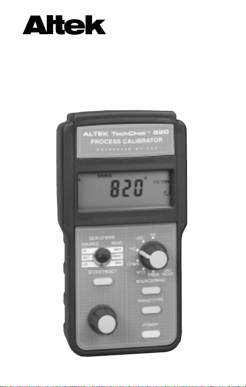
Process Calibrator
TechChek™ 820
Page 2

1
GENERAL INFORMATION
Lighten your load by taking the TechChek to every site. It’s like
bringing a cartload of test equipment from the shop to the control
room or the field. The TechChek 820 sources & reads DC like a
milliamp or voltage calibrator, simulates and measures T/Cs &
RTDs like a temperature calibrator and generates and counts
frequency & Counts-Per-Minute like a frequency calibrator. Your
TechChek can also help you trouble shoot like a multimeter! It
checks continuity and measures AC line voltage without carrying
a seperate instrument.
The TechChek 820 is easy to use. Select a function, choose a
range, and turn the knob for the precise output you need. Plus,
you can store three output values per range for instant recall with
the QUIK-CHEK®switch.
MILLIAMP CALIBRATION
Use at every point in your 4 to 20 mA loop. You can Source &
Read 0.00 to 24.00 mA, Simulate a Two-Wire Transmitter or the
use the TechChek 820 to simultaneously Power & Measure your
Two-Wire Transmitters.
VOLTAGE CALIBRATION
Calibrate all your DC millivolt and voltage instrumentation. Source
from 0.00 to 110.00 mV and 0.00 to 10.25 V. Read up to 110.00 mV,
11.00 V and 200.0 VDC.
THERMOCOUPLE CALIBRATION
Source and read directly in °C and °F for T/C types J, K, T& E with
1° resolution. Cold junction compensation automatically adjusts
for ambient temperature changes.
RTD CALIBRATION
Built-in Platinum 100 Ohm DIN/IEC 751 table displays in °C or °F.
No more decade box and hard-to-read tables. Also reads and
sources in Ohms.
GENERAL OPERATING INSTRUCTIONS...........................3
TURN ON.........................................................................3
CONNECTIONS...............................................................3
TILT STAND......................................................................4
CHANGING BATTERIES..................................................4
RESTORING DEFAULT SETTINGS ................................5
CONFIGURING TEMPERATURE SCALES ...............5
ENABLING AUTO-OFF ..............................................5
SELECTING RANGES.....................................................6
SOURCE MODE OPERATING INSTRUCTIONS .................7
STORING & RECALLING QUIK-CHEK
®
OUTPUTS .......7
SOURCE MODE CONNECTION INSTRUCTIONS
CALIBRATE MILLIAMP INPUTS................................8
SIMULATE 2-WIRE TRANSMITTERS .......................9
POWER & MEASURE 2-WIRE TRANSMITTERS...10
CALIBRATE VOLTAGE INPUTS...............................11
CHECK 1-5 VOLT INPUTS WITHOUT
DISCONNECTING WIRES.......................................12
CALIBRATE THERMOCOUPLE INPUTS................13
CALIBRATE RESISTANCE INPUTS ........................14
CALIBRATE RTD INPUTS .......................................15
CALIBRATE FREQUENCY INPUTS ........................16
READ MODE OPERATING INSTRUCTIONS....................17
MIN/MAX ..................................................................17
OUT OF RANGE SIGNALS......................................17
READ MODE CONNECTION INSTRUCTIONS
READ MILLIAMP OUTPUTS ....................................18
READ VOLTAGE OUTPUTS ....................................19
MEASURE THERMOCOUPLE SENSORS..............20
READ RESISTANCE................................................21
CHECK CONTINUITY..............................................22
MEASURE RTD SENSORS .....................................23
COUNT FREQUENCIES..........................................24
READ AC VOLT AGES..............................................25
SPECIFICATIONS...............................................................26
WARRANTY........................................................................30
CONTENTS
Page 3
2 3
OPERATING INSTRUCTIONS
GENERAL
TURN-ON
Each time you turn on the TechChek 820
the LCD will display all segments for about
1 second. It then displays the most recently selected Source or Read Setting.
SOURCE - The three QUIK-CHEK outputs
will be the same as previously stored. Each
time a different function is selected, the
three QUIK-CHEK outputs will be recalled.
READ - The 820 is ready to measure the
same signal as the last time it was turned
on and is automatically updating the MAX &
MIN readings for recall at any time.
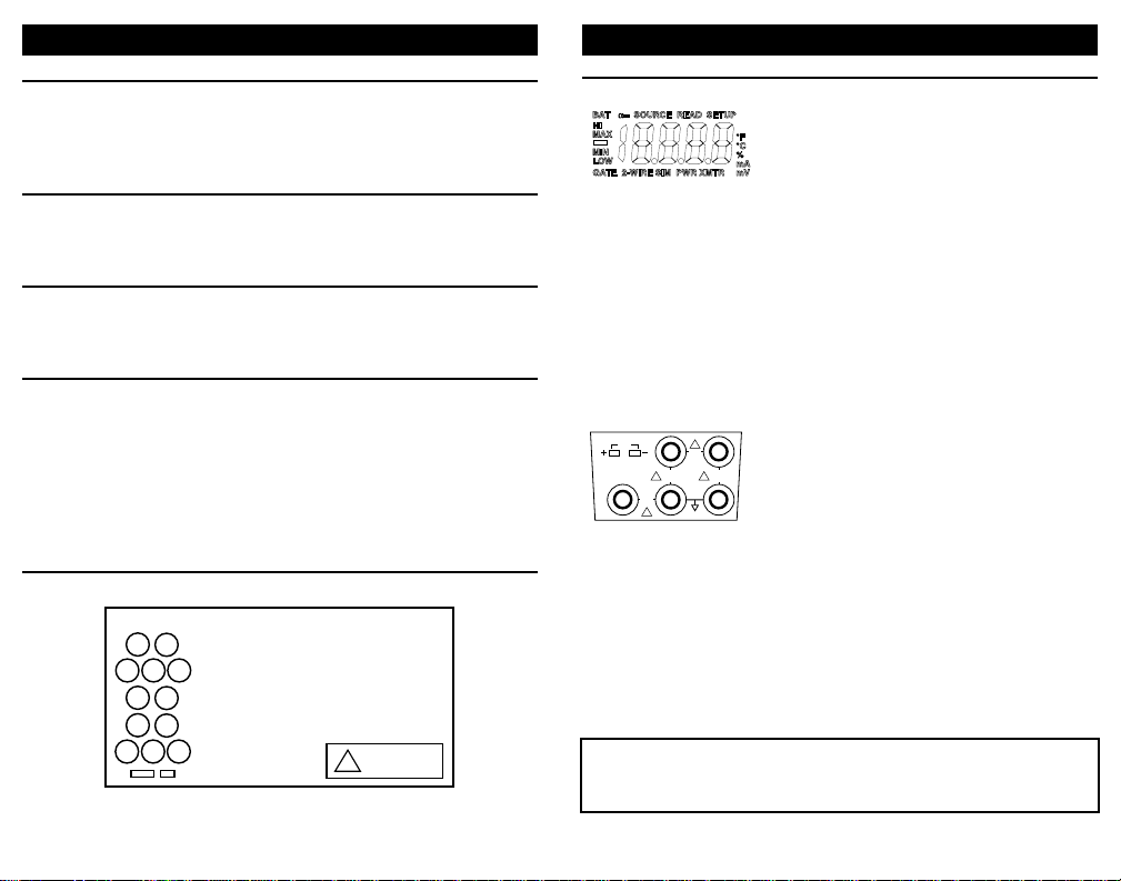
CONNECTIONS
TechChek 820 has protected banana jacks
compatible with standard and safety
banana plugs. Included with your
TechChek are: a pair of safety test leads
with test probes, safety alligator clips
standard alligator clips and spade lugs for
attachment to a wide variety of instruments.
An additional safety test lead and spade lug
are also included for 3-Wire RTD connections.
Thermocouple connections are made
through a miniature thermocouple socket.
Optional KIT-1 includes T/C wires for Type
J, T, E & K with miniature T/C plugs (not
included).
To prevent accidently overloading the instrument being tested, it
is important to correctly set up the outputs before connecting
TechChek 820 to any instruments to be calibrated.
GENERAL INFORMATION
FREQUENCY CALIBRATION
Generate Zero Crossing square waves from 1 to 1000 Hz, 0.01 to
10.00 kHz and from 1 to 1000 CPM (Counts-Per-Minute). Also
measures as a frequency counter.
MEASURE AC VOLTAGE
Check your line voltage or mains from 0.0 to 250.0 volts AC. Great
for troubleshooting power problems.
CHECK CONTINUITY
Locate pairs of wire, open connections and shorts with the built-in
beeper.
TECHNICIAN’S LEAD KIT
Included with the TechChek 820 is a test lead kit which consists of
three safety test leads with alligator clips, test probes and spade
lugs.
Rear Label - Condensed Operation Guide
SOURCE & READ T/C
TERMINALS FUNCTION
– +
SOURCE 3-Wire RTD
1– 4–
2+
READ 3-Wire RTD
1+ 2–
3–
READ Freq & VAC to 250V, VDC to 200V
4– 5+
READ mA, mVDC, Freq & VDC to 10.25V
SIMULATE 2-Wire Transmitters
4– 3+
SOURCE mA, mV, V, Ω, 2-Wire RTD, Freq
PWR/MEAS mA READ Ω CONTINUITY
1– 2+
!
See manual
for details.
T/C
23
!
45V
MAX
INPUT
45V MAX
5V MAX
!!
INPUT
300V
MAX
INPUT
INPUT
!
145
Page 4
GENERAL
CONFIGURING TEMPERATURE SCALES
The thermocouple and RTD ranges may be configured for full time
use of °C, full time use of °F or selectable °C and °F operation.
This configuration is part of the DEFAULT SETTINGS below.
AUTO-OFF
TechChek 820 can be set up to turn itself off after 30 minutes of
inactivity. The internal timer is reset to 30 minutes each time the
digital pot is turned or a pushbutton is pressed.
DEFAULT SETTINGS
TechChek 820 may be restored to the factory default setting. This
will reset the HI and LO “QUIK-CHEK” memories according to the
table below and the SET memory to midrange between HI and LO.
OPERATING INSTRUCTIONS
1) Press and hold the STORE/RESET push-button while turning
the 820 on.
2) Keep pressing the push-button until the display flashes (about
5 seconds) then release.
3) The °C & °F symbols will flash on the display.
4) Press the RANGE/TYPE push-button to make your selection.
With °C flashing the unit will only display in °C, With °F flashing the unit will only display in °F and with both flashing you can
select °C and °F for each T/C & RTD type. °C/°F is selected if
no push-buttons are pressed.
5) After five seconds the 820 will automatically store your choice
and the words BAT and ON will appear on the display indicating that AUTO-OFF is selected.
6) To toggle the AUTO-OFF function
on and off press the RANGE/TYPE
push-button and the words oN and
oFF will display.
7) After five seconds the 820 will
automatically store your choice.
8) All segments on the LCD will remain
displayed until the 820 has been
reset.
4
OPERATING INSTRUCTIONS
GENERAL
FIELD & BENCH USE
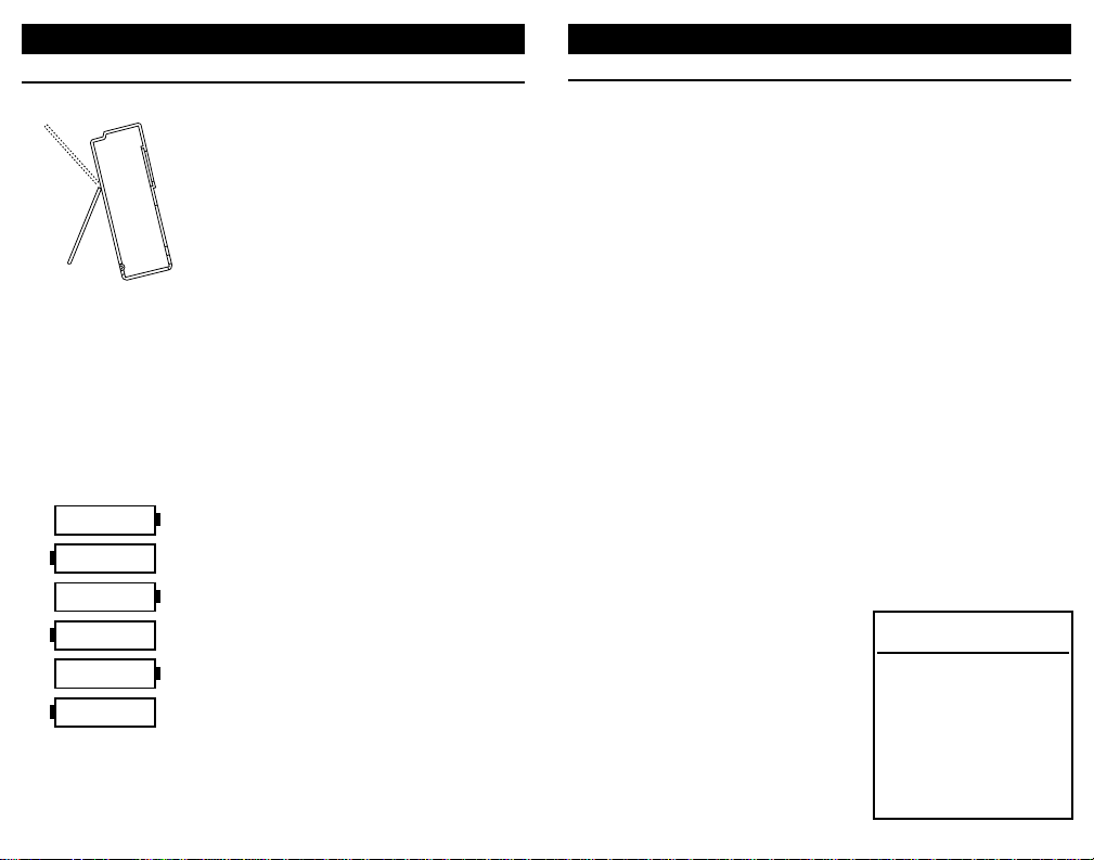
TechChek 820 comes with a carrying case
and a built-in tilt stand/hanger. The 820 is
held securely in the case by VELCRO® for
use with the carrying case open. The carrying case also has a snap-on belt loop which
can be looped around a pipe or rail.
The tilt stand is easily raised by pulling the
stand until it locks into place. The stand can
also be reversed for use as a hanger to
suspend the 820.
AUTOCAL
To maintain accuracy the TechChek periodically recalibrates its measuring circuitry
against internal references. While this is
occuring the word CAL will appear on the
display for less than 2 seconds.
CHANGING BATTERIES
Low battery is indicated by BAT on the
display. Approximately four hours of operation remain before the LCD blanks and
TechChek 820 shuts itself down. Turn the
820 off, loosen the captive screw securing
the battery compartment and lift off the
cover from the bottom of the case. The six
“AA” batteries are easily removed and
replaced (alkaline supplied and recommended). Replace the battery compartment
cover by inserting the tabs and tightening
the screw.
5
QUIK-CHEK
DEFAULTS
RANGE LO SET HI
mA 4.00 12.00 20.00
mV 1.00 5.00 10.00
V 1.00 5.00 10.00
T/C All points 0°C/32°F
Ohms 100.0 200.0 400.0
RTD All points 0°C/32°F
kHz 1.00 5.00 10.00
Hz 100 500 1000
CPM 100 500 1000
CAL
Page 5
7
SOURCE MODE
Select source by pressing the SOURCE/READ pushbutton until
the word SOURCE appears on the LCD display. To change the
output value, turn the speed sensitive digital pot. Turning the knob
slowly will cause a gradual change in the output. A faster rate of
change will occur when the knob is turned faster. This function
operates in all three output positions (HI, SET & LO).
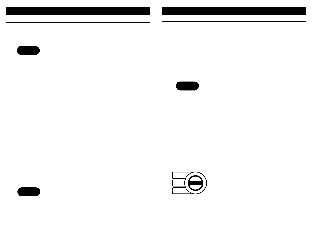
STORING QUIK-CHEK OUTPUTS
1) Switch to HI or LO
2) Turn the knob to desired value
3) Press the STORE push-button
The LCD will flash once to show that the
value was saved
If a value is in the SET position and you
want that value stored in HI or LO, press
and hold the STORE push-button while
moving the switch to HI or LO. The display
will flash once to indicate the value has
been stored. Then release the STORE
push-button.
RECALLING QUIK-CHEK OUTPUTS
When you need a stored value just flip the
QUIK-CHEK switch. Any value for the
selected range may be stored in HI & LO.
The TechChek 820 remembers the HI, LO
and SET values for each function with the
power on or off. Each time a different
function is selected, the last three QUIKCHEK values for that function will be
recalled.
OPERATING INSTRUCTIONS
6
OPERATING INSTRUCTIONS
GENERAL
SELECTING RANGES
Press the RANGE/TYPE pushbutton to
select the desired range and scale.
SOURCE RANGES
Milliamp: mA, %mA, 2-Wire Sim, %2-Wire Sim, Pwr Xmtr, %Pwr Xmtr
VDC: mV, V
T/C: J°F, J°C, T°F, T°C, E°F, E°C, K°F, K°C
Ohms: Ohms
RTD: Pt °F, Pt °C
Frequency: KHz, Hz, CPM
READ RANGES
Milliamp: mA, %mA
VDC: mV, 10V, 200V
T/C: J°F, J°C, T°F, T°C, E°F, E°C, K°F, K°C
Ohms: Ohms, Continuity
RTD: Pt °F, Pt °C
Frequency: KHz, Hz, CPM
VAC: VAC
TURN OFF
Press the POWER push-button to turn the
820 off. If AUTO-OFF is enabled the 820
will turn itself off after 30 minutes of inactivity.
RANGE/TYPE
POWER
STORE/RESET
SOURCE
HI
SET
LO
Page 6
9
OPERATING INSTRUCTIONS
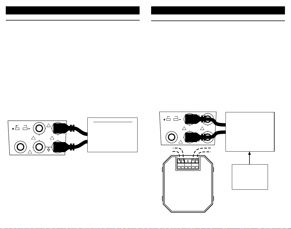
SIMULATE 2-WIRE TRANSMITTERS
2-WIRE SIM mA, 2-WIRE SIM % (Percent of 4 to 20 mA)
Choose this function to simulate a 2-Wire Transmitter output from
1.00 to 24.00 milliamps. Operates in loops with power supply
voltages from 3 to 45 VDC.
1) Disconnect existing 2-Wire Transmitter from the loop
2) Connect the red SOURCE lead of the calibrator to the plus (+)
input of the field connections and the black SOURCE lead to
the minus (-)
3) Repeatedly press the RANGE/TYPE push-button until the words
SOURCE, 2-WIRE SIM and mA or SOURCE, 2-WIRE SIM and
% are displayed.
The simulated output of the 2-Wire Transmitter is continuously
adjustable from 1.00 to 24.00 mA with the "QUIK-CHEK" switch in
the SET position. Zero & Span (or any other values) are available
by using the LO and HI "QUIK-CHEKs".
8
CALIBRATE MILLIAMP INPUTS
mA, mA % (Percent of 4 to 20 mA)
Choose this function to provide an output from 0.00 to 24.00
milliamps. The compliance voltage is a nominal 25 VDC to provide
the driving power to your milliamp receivers.
1) Disconnect one or both input wires from the device to be
calibrated.
2) Connect the red SOURCE lead of the calibrator to the plus (+)
input of the device and the black SOURCE lead to the minus (-).
3) Repeatedly press the RANGE/TYPE push-button until the word
SOURCE and mA or SOURCE and % are displayed.
Output current is continuously adjustable with the "QUIK-CHEK"
switch in the SET position. Zero & Span (or any other values) are
available by using the LO and HI "QUIK-CHEKs".
OPERATING INSTRUCTIONS
T/C
23
!
45V
RED
MAX
INPUT
300V
MAX
INPUT
45V MAX
INPUT
!
5V MAX
!!
INPUT
BLACK
145
Milliamp Receiver Input
Controller
Transmitter
Computer
Logger
I/P
DCS
Sensor
RED
45V MAX
INPUT
BLACK
REF +OUT-
45V
MAX
INPUT
23
!
5V MAX
!!
INPUT
145
T/C
300V
MAX
INPUT
!
To
+IN-
Receiver
(Powers external
2-Wire Transmitter)
Typical
2-Wire
Transmitter
(Disconnected)
Power Supply
2 to 45 VDC
Page 7
11
CALIBRATE VOLTAGE INPUTS
V, mV
Choose this function to provide an output from 0.00 mV to 110.00
mV and from 0.00 to 10.25 VDC. Source current is a nominal 20
mA to provide the driving power to your voltage receivers.
1) Disconnect one or both input wires from the device to be
calibrated
2) Connect the red SOURCE lead of the calibrator to the plus (+)
input of the device and the black SOURCE lead to the minus (-)
3) Press the RANGE/TYPE push-button to switch the display
between mV and V.
Output voltage is continuously adjustable with the "QUIK-CHEK"
switch in the SET position. Zero & Span (or any other values) are
available by using the LO and HI "QUIK-CHEKs".
OPERATING INSTRUCTIONS
10
OPERATING INSTRUCTIONS
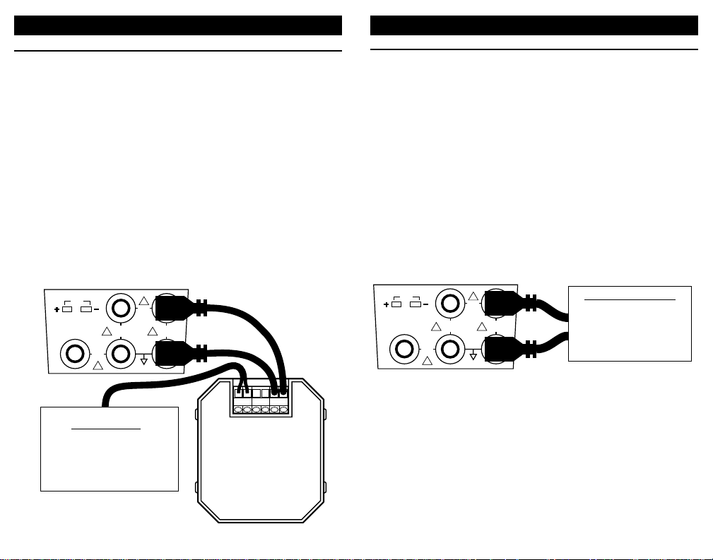
POWER & MEASURE 2-WIRE TRANSMITTERS
PWR XMTR mA, PWR XMTR %
Choose this function to simultaneously supply power to a 2-Wire
transmitter while displaying the 4-20 mA output of the transmitter.
1) Disconnect one or both input wires from the 2-Wire Transmitter
to be calibrated
2) Connect the red SOURCE lead of the calibrator to the plus (+)
input of the device and the black SOURCE lead to the minus (-)
3) Connect an appropriate sensor or calibrator to the input of the
2-Wire Transmitter
3) Repeatedly press the RANGE/TYPE push-button until the words
SOURCE, PWR XMTR and mA or SOURCE, PWR XMTR and
% are displayed.
TechChek 820 supplies a nominal 24 Volts DC at 24 mAto the 2Wire transmitter. The current passed by the transmitter will be
accurately displayed by the 820. Calibrate the Transmitter in the
usual manner and disconnect the 820.
+IN-
REF +OUT-
!!
145
23
5V MAX
INPUT
45V MAX
INPUT
!
300V
MAX
INPUT
45V
MAX
INPUT
!
T/C
RED
BLACK
Transmitter Input
Sensor
Process Signal
Simulated Input
Typical
2-Wire
Transmitter
T/C
23
!
45V
RED
MAX
INPUT
300V
MAX
INPUT
45V MAX
INPUT
!
5V MAX
!!
INPUT
BLACK
145
Voltage Receiver Input
Controller
Transmitter
Computer
Logger
DCS
Page 8
13
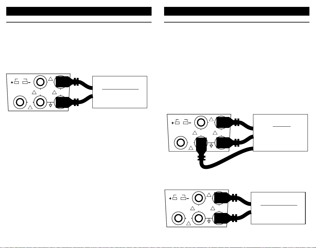
CALIBRATE THERMOCOUPLE INPUTS
Choose this function to simulate a thermocouple signal into any
instrument requiring a thermocouple input. The output of the 820
is automatically cold junction compensated.
1) Disconnect the thermocouple from the instrument being
calibrated.
2) Press the RANGE/TYPE push-button until the desired T/C type
and temperature scale appear.
3) Use a thermocouple wire and corresponding miniature thermocouple connector to connect the TechChek 820 to the instrument.
Output temperature is continuously adjustable with the "QUIKCHEK" switch in the SET position. Zero & Span (or any other
values) are available by using the LO and HI "QUIK-CHEKs"
OPERATING INSTRUCTIONS
12
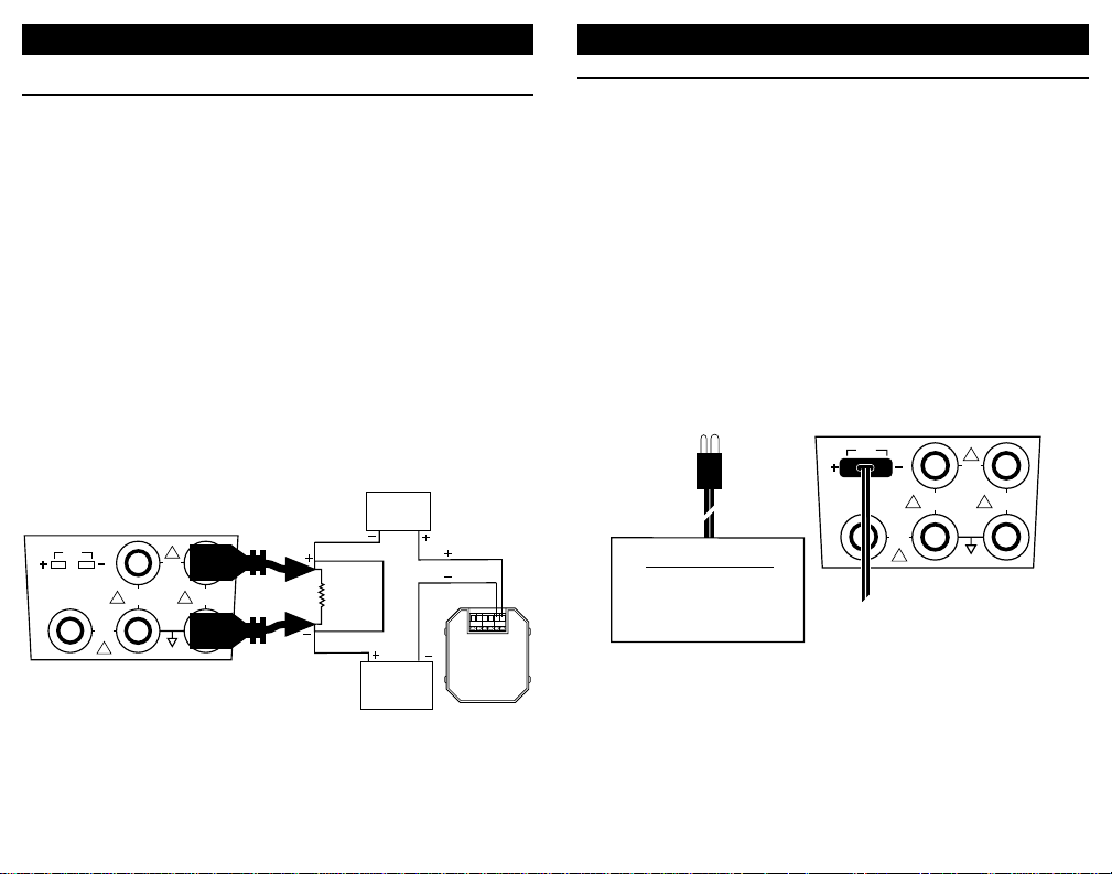
CHECK 1-5 VOLT INPUTS
WITHOUT DISCONNECTING WIRES
Most 1-5 Volt receivers in 4-20mAloops have a 250 Ohm resistor across the input of the receiver. This resistor may be mounted
internally or externally. TechChek 820 is connected directly across
the input of the 1-5 Volt receiver without disconnecting any field
wiring. This saves a great deal of time when a large number of
voltage receivers, such as chart recorders or computer systems,
require calibration.
Make certain that changing the signal input will not disturb the
process or cause unexpected alarms when checking on-line
instruments. It is important to remember the 820 drives only the
device to which it is connected. It has no effect on other devices
in the 4 to 20 mA loop. TechChek 820 will clamp the selected
value in the mV and V Ranges to the maximum sink current of >16
mA.
1) Connect the red SOURCE lead of the calibrator to the plus (+)
input of the device and the black SOURCE lead to the minus (-).
OPERATING INSTRUCTIONS
45V MAX
INPUT
MAX
INPUT
45V
!
23
RED
5V MAX
!!
INPUT
BLACK
145
T/C
300V
MAX
INPUT
!
250Ω
RECORDER
COMPUTER
LOGGER
ETC,
1-5V DC
CONTROLLER
(TYPICAL)
ADDITIONAL
4-20 mA OR 1-5V
INSTRUMENTS
+IN-
REF +OUT-
Typical
2-Wire
Transmitter
-
+
Instrument with
Thermocouple Input
Controller
Temperature Indicator
Temperature Trip or Alarm
Temperature T ransmitter
T/C
5
300V
MAX
INPUT
23
!
45V
MAX
INPUT
45V MAX
INPUT
!
4
!!
1
5V MAX
INPUT
Page 9
15
CALIBRATE RTD INPUTS
Choose this function to simulate a temperature signal into any
instrument requiring an RTD input.
1) Disconnect the sensing RTD from the instrument being
calibrated.
2) Press the RANGE/TYPE push-button until the desired RTD
type and temperature scale appear.
3) Connect using 3 or 2 wires as in the diagrams below. Spade
lugs are recommended to minimize any contact resistance.
Output temperature is continuously adjustable with the "QUIKCHEK" switch in the SET position. Zero & Span (or any other
values) are available by using the LO and HI "QUIK-CHEK”
positions.
OPERATING INSTRUCTIONS
14
CALIBRATE RESISTANCE INPUTS
Choose this function to simulate a resistance into a variety of
instruments.
1) Disconnect one or both input wires from the device to be
calibrated.
2) Connect the red SOURCE lead of the calibrator to the plus (+)
input of the device and the black SOURCE lead to the minus (-).
OPERATING INSTRUCTIONS
Three Wire RTD Connection
Two Wire RTD Connection
T/C
23
!
45V
RED
MAX
INPUT
300V
MAX
INPUT
45V MAX
INPUT
!
5V MAX
!!
INPUT
BLACK
145
Receiver Input
Ohms or 2-Wire RTD
Controller
Transmitter
Computer
T/C
300V
MAX
INPUT
5
T/C
300V
MAX
INPUT
!
23
!
45V
RED
MAX
INPUT
45V MAX
INPUT
!
4
BLACK
5V MAX
!!
INPUT
BLACK
1
23
!
45V
RED
MAX
INPUT
45V MAX
INPUT
!!
5V MAX
INPUT
BLACK
145
Instrument with
RTD Input
Controller
Temperature T ransmitter
Temperature Indicator
Temperature Trip or Alarm
Receiver Input
Ohms or 2-Wire RTD
Controller
Transmitter
Computer
Page 10
1716
READ FUNCTIONS
Select read by pressing the SOURCE/READ pushbutton until the
word READ appears on the LCD display. The READ functions
measure the desired signal. Multiple scales are available for some
functions.
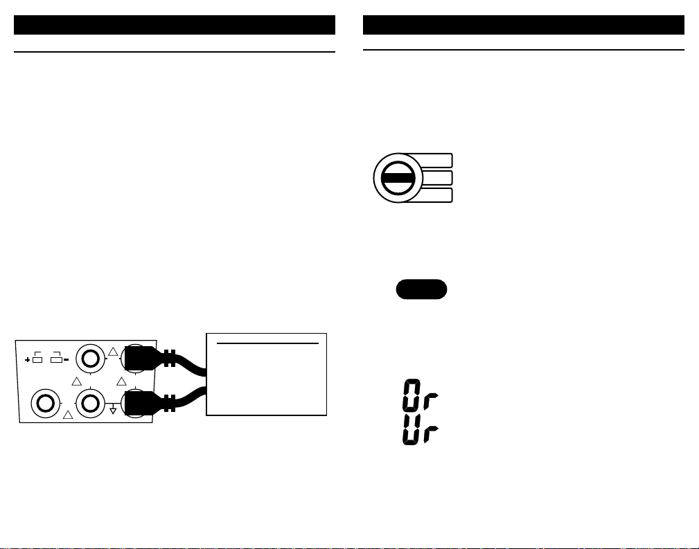
MIN/MAX
To read the Maximum or Minimum INPUT
since READ mode was entered, simply
switch to MAX or MIN. The value will
appear on the LCD along with the word
MAX or MIN. The MAX/MIN values are
automatically updated and may be viewed
at any time without disturbing the other
values.
RESTARTING
MIN/MAX
Pressing the STORE/RESET push-button
will cause the 820 to store the present
reading into the MAX and MIN memories.
Upon releasing the STORE/RESET pushbutton the 820 will resume reading the input
and update the MAX & MIN values as the
measured signal changes.
OUT OF RANGE
SIGNALS
Signals above or below those available for
the currently selected range will be indicated by Or and Ur on the display.
OPERATING INSTRUCTIONS
CALIBRATE FREQUENCY INPUTS
Choose this function to provide pulses into frequency measuring
instruments. The 820 output is a zero crossing square wave from
-1V to +5V amplitude. Available ranges are from 0.01 to 10.00
kHz, 1 to 1000 Hz and from 1 to 1000 CPM (Counts-Per-Minute).
CPM is used to simulate extremely slow frequency signals with
greater resolution. For example, 10 Hz is equivalent to 600 CPM.
To convert from CPM to Hz Divide by 60. To convert from Hz to
CPM multiply by 60.
1) Disconnect any input from the instrument being calibrated.
2) Press the RANGE/TYPE push-button until the desired frequency range appears.
3) Connect the red SOURCE lead of the 820 to the plus (+) input of
the device and the black SOURCE lead to the minus (-).
Output frequency is continuously adjustable with the "QUIKCHEK" switch in the SET position. Zero & Span (or any other
values) are available by using the LO and HI "QUIK-CHEKs"
OPERATING INSTRUCTIONS
READ
MAX
READ
MIN
Frequency Receiver Input
Flowmeter
Controller
Transmitter
Computer
Logger
DCS
45V MAX
INPUT
45V
MAX
INPUT
!
23
RED
5V MAX
!!
INPUT
BLACK
145
T/C
300V
MAX
INPUT
!
STORE/RESET
Page 11
19
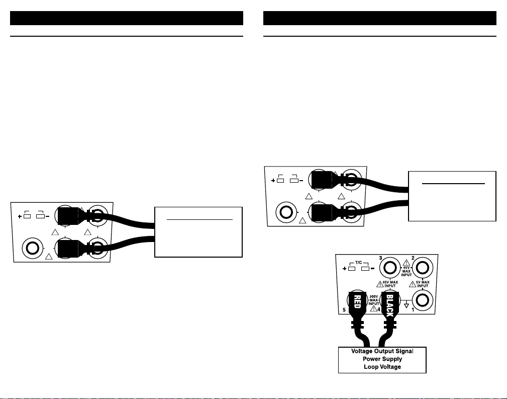
READ DC VOLTAGE OUTPUTS
V, mV
Choose this function to measure from 0.00 to 10.25 DC Volts. For
checking low level sensor outputs and other low levels change the
input range to display from 0.00 to 110.00 millivolts. Use the high
voltage connection to read from 0.0 to 200.0 VDC
1) Connect the red READ (+) lead and the black READ (-) lead of
the calibrator across the voltage to be measured.
Signals above or below those available for the currently selected
range will be indicated by OVER and UNDER on the display.
OPERATING INSTRUCTIONS
Connection for millivolts and Volts below 10.25 VDC
Connection for Volts to 200.0 VDC
18
READ MILLIAMP OUTPUTS
mA, mA % (Percent of 4 to 20 mA)
Choose this function to measure from 0.00 to +24.00 milliamps or
-25.0 to 125.0%.
1) Open the current loop at any convenient point along the signal
path
2) Connect the red READ (+) lead of the calibrator to the more
positive point of the break and the black READ lead (-) to the
more negative
Display the present reading, Maximum or Minimum by moving the
toggle switch from READ to MAX or MIN. If TechChek 820 is
connected in the wrong polarity, the word POLARITY will appear
in the display. Simply reverse the leads for correct indication.
OPERATING INSTRUCTIONS
T/C
300V
MAX
INPUT
23
!
45V
RED
MAX
INPUT
!
45V MAX
INPUT
BLACK
!!
145
5V MAX
INPUT
Milliamp Output Signal
Controller
Transmitter
P/I
DCS
T/C
23
!
45V
RED
MAX
INPUT
300V
MAX
INPUT
!
45V MAX
INPUT
BLACK
!!
145
5V MAX
INPUT
Voltage Output Signal
Controller
Transmitter
Power Supply
Page 12
21
READ RESISTANCE
Ohms
Choose this function to measure resistance from 0.0 to 1000.0
Ohms.
1) Connect the red READ (+) lead and the black READ (-) lead of
the calibrator across the resistance to be measured.
Signals above or below those available for the currently selected
range will be indicated by OVER and UNDER on the display.
OPERATING INSTRUCTIONS
20
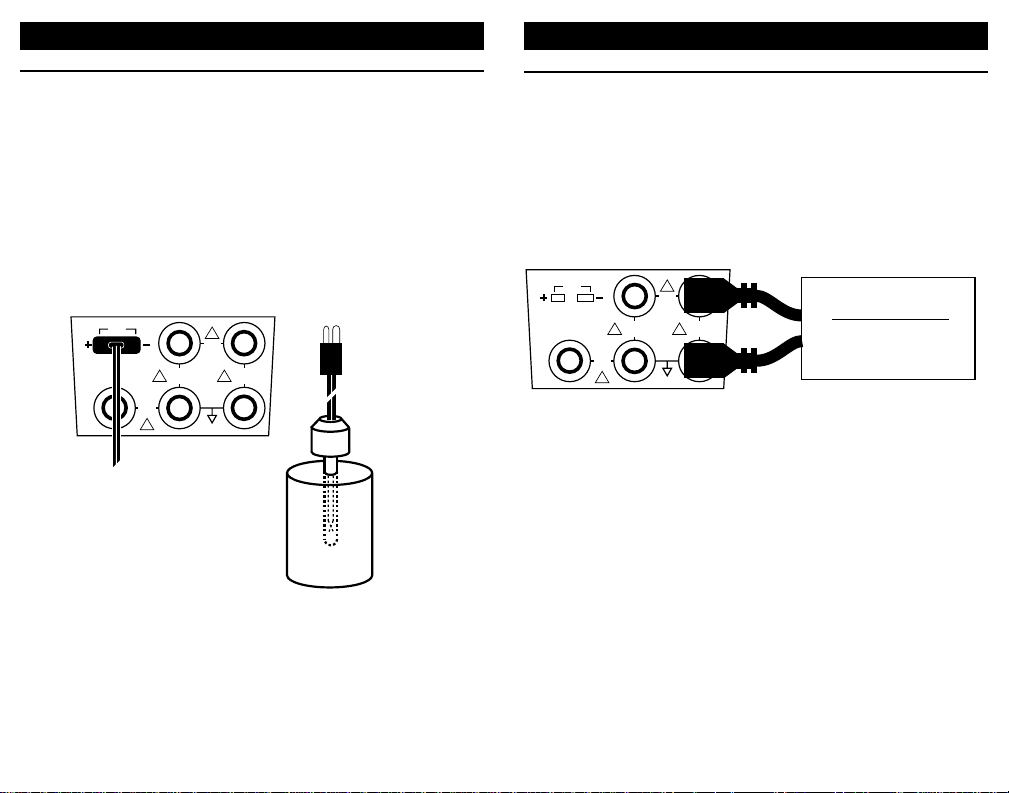
MEASURE THERMOCOUPLE SENSORS
Choose this function to read a thermocouple. The input of the
TechChek 820 is automatically cold junction compensated.
1) Disconnect the thermocouple from any instrument.
2) Press the RANGE/TYPE push-button until the desired T/C type
and temperature scale appear.
3) Use the proper thermocouple wire and corresponding miniature thermocouple connector to connect TechChek 820 to the
thermocouple.
OPERATING INSTRUCTIONS
45V MAX
INPUT
45V
MAX
INPUT
!
23
RED
5V MAX
!!
INPUT
BLACK
145
Receiver Input
Ohms or 2-Wire RTD
Controller
Transmitter
Computer
T/C
45V MAX
INPUT
45V
MAX
INPUT
23
!
5V MAX
!!
INPUT
1
-
+
300V
MAX
INPUT
!
T/C
300V
MAX
INPUT
!
5
4
Page 13
23
MEASURE RTD SENSORS
Choose this function to read an RTD. Three wires must be use for
both 2 and three wire RTDs.
1) Disconnect the RTD from any instrument.
2) Press the RANGE/TYPE push-button until the desired RTD
type and temperature scale appear.
3) Connect using 3 wires as in the diagrams below. Spade lugs
are recommended to minimize any contact resistance.
OPERATING INSTRUCTIONS
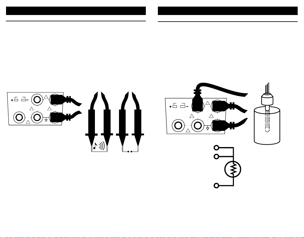
CHECK CONTINUITY
Choose this function to check continuity. A tone will sound and a
sound symbol will appear on the display when the resistance
between the leads is less than 100 Ohms.
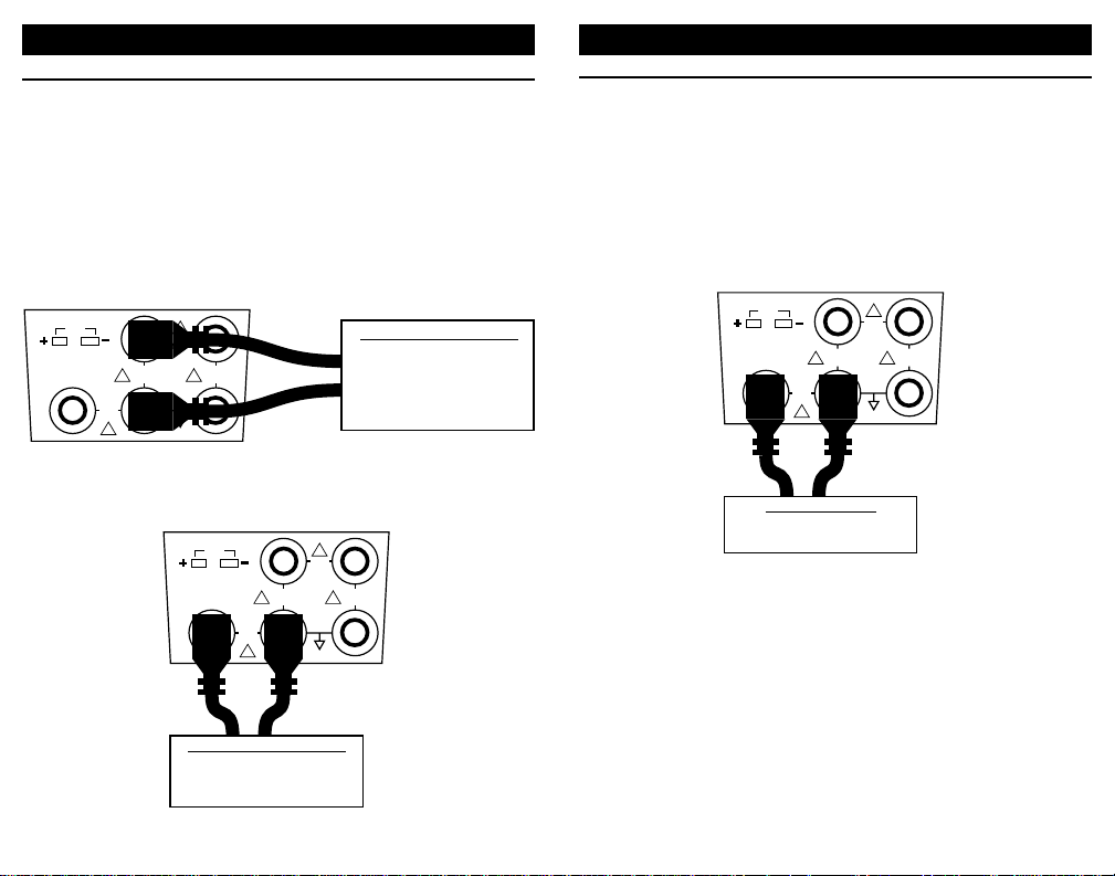
1) Plug the leads into the TechChek 820 as shown below.
2) Turn the selector knob to OHMs
3) Press the SOURCE/READ pushbutton until the word READ
appears on the display.
4) Press the RANGE/TYPE pushbutton until the word
CONTINUITY appears on the display
22
OPERATING INSTRUCTIONS
45V MAX
INPUT
MAX
INPUT
45V
!
23
RED
5V MAX
!!
INPUT
BLACK
145
45V MAX
INPUT
!
45V
MAX
BLACK
INPUT
23
BLACK
5V MAX
!!
INPUT
RED
145
3
2
T/C
300V
MAX
INPUT
!
BLACK
BLACK
T/C
300V
MAX
INPUT
!
RTD Element
RED
1
Page 14
25
READ AC VOLTAGES
Choose this function to measure from 0.0 to 250.0 V True RMS.
CAUTION: Care should be used when measuring AC voltage.
The included safety test probes or safety alligator clips should be
used. Do not exceed voltage limits shown on calibrator.
OPERATING INSTRUCTIONS
24
COUNT FREQUENCIES
Choose this function to use the 820 as a frequecny counter.
Availible ranges are from 0.01 to 10.00 kHz, 1 to 1000 Hz and
from 1 to 1000 CPM (Counts-Per-Minute).
To measure waveforms with amplitudes between 1 V and 10.25 V
RMS use the low level inputs. Use the high voltage connection to
read waveforms with amplitudes from 10.25 to 250.0 V RMS
OPERATING INSTRUCTIONS
Connection for signals with amplitudes below 10.25 V RMS
Connection for signals with amplitudes to 250 V RMS
T/C
300V
MAX
INPUT
!
RED
45V MAX
INPUT
BLACK
45V
MAX
INPUT
23
!
5V MAX
!!
INPUT
145
Frequency Output Signal
Flowmeter
Flow Sensor
Variable Speed Drive
Controller
Transmitter
45V MAX
INPUT
RED
45V
MAX
INPUT
23
!
5V MAX
!!
INPUT
1
T/C
BLACK
300V
MAX
INPUT
!
5
Frequency Output Signal
4
Flow Meter
Line Frequency
Variable Speed Drives
T/C
BLACK
300V
MAX
INPUT
5
AC Voltage Signal
Line Voltage
!
4
Mains
45V MAX
INPUT
RED
45V
MAX
INPUT
23
!
5V MAX
!!
INPUT
1
Page 15
POWER & MEASURE 2-WIRE TRANSMITTERS
RANGES & ACCURACY: Same as for MILLIAMP SOURCE
OUTPUT CURRENT: up to 24.00 mA
TYPICAL DRIVE CAPABILITY:1200 Ohms @ 20.00 mA
COMPLIANCE VOLTAGE: nominal 25 VDC @ 20 mA
2-WIRE TRANSMITTER SIMULATOR
RANGES:
1.00 to 24.00 mA; -18.8 to 125.0% of 4 to 20 mA
ACCURACY: Same as for MILLIAMP SOURCE
LOOP VOLTAGE LIMITS: Mininum, 3 VDC; Maximum 45 VDC
OVERLOAD PROTECTION: Current limited to 25 mA nominal
MILLIAMP READ
RANGES:
0.00 to 24.00 mA; -25.0 to 125.0 % of 4 to 20 mA
ACCURACY: Same as for MILLIAMP SOURCE
OVERLOAD PROTECTION: Current limited to 25 mA nominal
VOLTAGE BURDEN: 0.9V at 4 mA, 1.2V at 20 mA, 1.9V at 24 mA
DC VOLTAGE SOURCE
RANGES:
0.00 to 110.00 mV; 0.00 to 10.25V
ACCURACY:
±(0.05% of 110 mV+ 0.01mV) = ±0.07 mV
±(0.05% of 10.25 V + 0.01V) = ±0.02V
SOURCE CURRENT: >20 mA
SINK CURRENT: >20 mA
OUTPUT IMPEDANCE: <0.3 Ohms
SHORT CIRCUIT DURATION: Infinite
MEASURE AC VOLTS
RANGE: 0.0 to 250.0 V True RMS
ACCURACY:From 10 to 250 V AC ±(2% of 250 V + 0.1 VAC) = ±5.1 VAC
MAXIMUM CREST FACTOR:< 3
FREQUENCY RANGE: 45 to 800 Hz
27
SPECIFICATIONS
26
GENERAL
TYPICAL 90 DAYACCURACY : ± (0.025% of Full Scale + 1 LSD)
1
1 YEAR ACCURACY: ±(0.05% of Full Scale + 1 LSD)
WARM UP TIME: 10 seconds to specified accuracy, 2 minutes to
maximum accuracy
TEMPERATURE EFFECT: ±0.01%/°C based on 23°±25°C
BATTERIES: Six “AA”, (R6) batteries (Alkaline supplied and
recommended)
BATTERY LIFE:
MILLIAMP SOURCE & 2-WIRE MODES: Nominal 50 hours at
12 mA, 20 hours at 20 mA with 250 Ohm load
OTHER FUNCTIONS: Nominal 50 hours
LOW BATTERY INDICATION: “BAT” indication on the display at
approximately 4 hours left
OVERLOAD PROTECTION: Three fuses, 250 mA [need rating]
NOISE: ≤1 LSD at frequencies less than 10 Hz
NORMAL MODE REJECTION RATIO: 50 dB @ 50/60 Hz
OPERATING TEMPERATURE RANGE: -5 to +130 °F (-20 to +55°C)
STORAGE TEMPERATURE RANGE: -13 to +130°F (-25 to +55°C)
RELATIVE HUMIDITY: 10 to 90%, non-condensing for 24 hours
from 0 to 35°C
OVERALL SIZE: 158.1 x 83.1 x 49.3 mm (6.23 x 3.27 x 1.94
inches)
WEIGHT: 0.6 kg (1 lb, 5 oz)
MILLIAMP SOURCE
RANGES:
0.00 to 24.00 mA; -25.0 to 125.0 % of 4 to 20 mA
ACCURACY: ±(0.05% of 24 mA Span + 0.01 mA) = 0.02mA
TYPICAL DRIVE CAPABILITY: 1200 Ohms @ 20.00 mA
COMPLIANCE VOLTAGE: nominal 25 V @ 20 mA
SPECIFICATIONS
1
Typical 90 day accuracy can be estimated by dividing the 1
year % of full scale accuracy by 2. Additions to the specification,
such as + 1 LSD, remain constant.
Page 16

ACCURACY RTD: ±1°C (At 1 mAExcitation Current)
RTD Type: Pt 100 Ohm DIN/IEC 751, Alpha = 1.3850 (0.00385)
RANGE RTD: -100 to 850°C; -148 to 1562°F
TEMPERATURE EFFECT: ±((0.035 mV/°C)*(1/mAExcitation Current))
ALLOWABLE EXCITATION CURRENT: 0.125 to 2.0 mAcontinu-
ous DC
READ RTD & OHMS
RANGE OHMS: 0.0 to 1000.0 Ohms
ACCURACY: ±(0.05% of 1000.0 Ohms + 0.1 Ohm) = ±0.6 Ohms
RTD RANGE & ACCURACY: Same as for SOURCE RTDs
EXCITATION CURRENT SUPPLIED: 1 mA, nominal
FREQUENCY SOURCE
RANGES: 1 to 1000 CPM (Count-Per-Minute); 1 to 1000 Hz,
0.01 to 10.00 kHz
ACCURACY:
±(0.05% of 1000 CPM + 1 CPM) = ±2 CPM
±(0.05% of 1000 Hz + 1 Hz) = ±2 Hz
±(0.05% of 10.00 kHz + 0.01 kHz) = ±0.02 kHz
OUTPUT WAVEFORM: Square Wave, Zero Crossing, -1V to +5V
± 10%
RISETIME: Hz <5 microseconds; CPM <100 microseconds
OUTPUT IMPEDANCE: <100 Ohms
SOURCE CURRENT: >1 mA at 10 kHz
SHORT CIRCUIT DURATION: Infinite
MEASURE FREQUENCY
RANGES & ACCURACY: Same as for FREQUENCY SOURCE
TRIGGER LEVEL: 1 V RMS, DC coupled
INPUT IMPEDANCE: > 1Meg Ohm + 60 pF
CONTINUITY CHECKING
TEST CURRENT: Nominal 1 mA
THRESHOLD: 100 Ohm ±20%
INDICATION: Steady tone & Symbol on LCD plus Ohm Reading
29
SPECIFICATIONS
MEASURE DC VOLTS
RANGES:
0.00 to 110.00 mV; 0.00 to 10.25 V; 0.0 to 200.0 V
ACCURACY:
±(0.05% of 110 mV+ 0.01mV) = ±0.07 mV
±(0.05% of 10.25 V + 0.01V) = ±0.02V
±(2% of 200.0 V + 0.1V) = ±4.1 V
INPUT RESISTANCE: >1 Meg Ohm to 10.25V, >5 Meg Ohm to
200V
SOURCE RESISTANCE EFFECT: 0.01% per 100 Ohms
SOURCE THERMOCOUPLES
RANGES:
Type J -100 to 1200°C; -148 to 2192°F
Type K -100 to 1371°C; -148 to 2500°F
Type T -100 to 400°C; -148 to 752°F
Type E -100 to 1000°C; -148 to 1832°F
ACCURACY:
1°C for temperatures above 0°C
2°C for temperatures below 0°C
COLD JUNCTION ACCURACY: ±1°C
COLD JUNCTION EFFECT: within 0.05°C per °C change
OVERLOAD PROTECTION: Fused
OUTPUT IMPEDANCE: <0.3 Ohms
SOURCE CURRENT: :>20 mA
READ THERMOCOUPLES
RANGES & ACCURACY: Same as for SOURCE THERMOCOUPLES
INPUT IMPEDANCE: > 1 Meg Ohm
OPEN THERMOCOUPLE DETECTION: 450 millisecond pulse.
Nominal threshold, 10 K Ohms.
SOURCE RTD & OHMS
RANGE OHMS: 0.0 to 400.0 Ohms
ACCURACY:±0.05% of Full Scale + 0.075 mV/mAExcitation Current
ACCURACY OHMS: ±(0.05% of 400.0 Ohms + 0.1 Ohm = ±0.3
Ohms (At 1 mA Excitation Current)
28
SPECIFICATIONS
Page 17

3130
NOTES
WARRANTY
Altek products are warranted to be free from defects in material
and workmanship (excluding fuses, batteries and leads) for a
period of three years from the date of shipment. Warranty repairs
can be obtained by returning the equipment prepaid to our factory.
Products will be replaced, repaired, or adjusted at our option. Altek
gives no other warranties, including any implied warranty of fitness
for a particular purpose. Also, Altek shall not be liable for any
special, indirect, incidental or consequential damages or losses
arising from the sale or use of its products.
Page 18

32
ORDERING INFORMATION Part No.
MODEL 820 TechChek 820
PROCESS CALIBRATOR
Included with each Model 820 are:
Carrying Case with belt loop and shoulder strap
Test Lead Kit
NOTES
Page 19

PN 1839053 Rev A April 2002
©2002 Altek Industries, Inc. Specifications subject to change without notice.
All rights reserved. Printed in U.S.A.
 Loading...