

Page 1
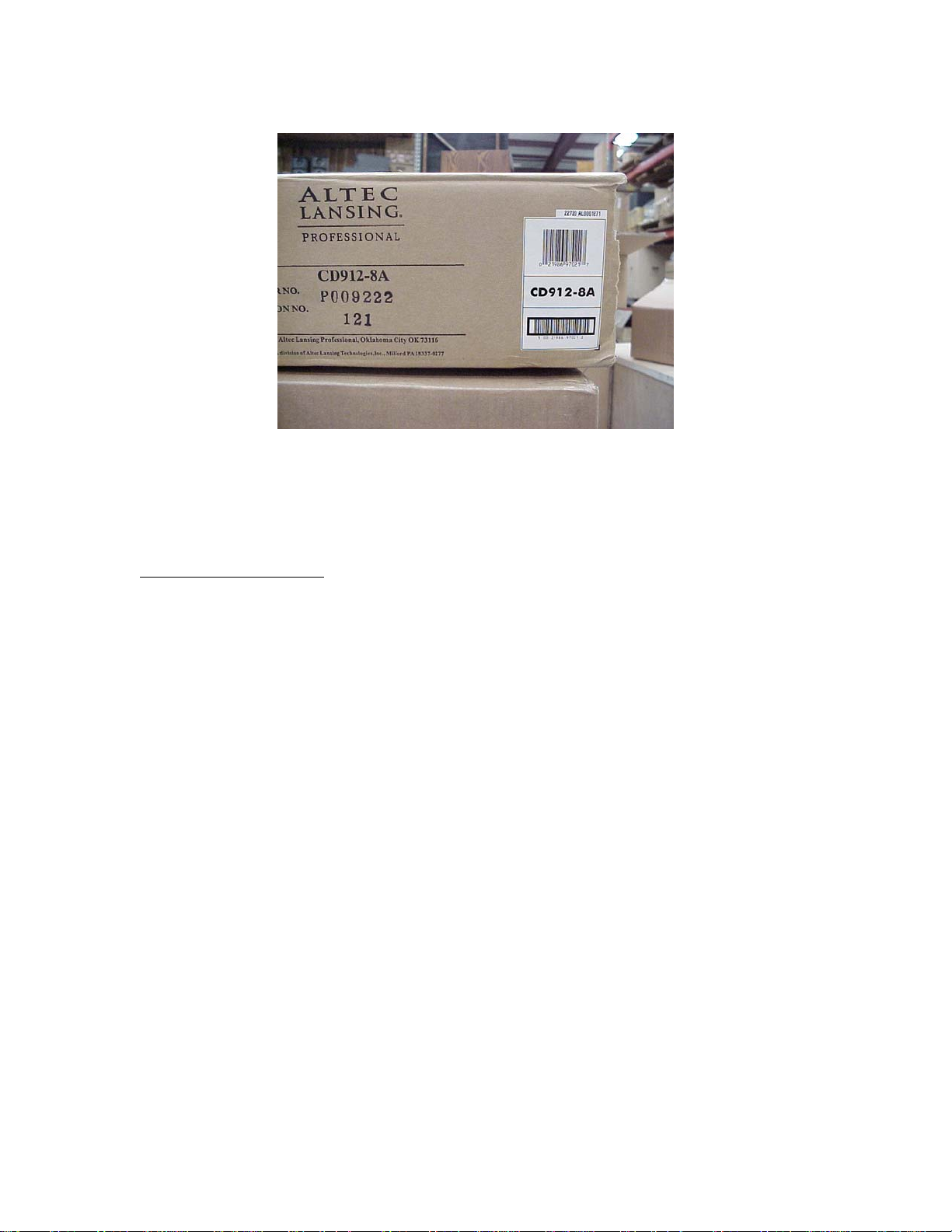
Figure 2
Date Code Label located on the CD912-8A’s Shipping Container is located, in upper
right just above the Universal Product Code Label.
Tools/Material Required
• High Frequency Voice Coil Assembly Kit (Part No. CD912-8-DRK)
• Philip Screw Driver (Small Tip)
• Long Nose Pliers (Fine)
• 1” Wide Scraper
• Wide, Thin, Flat Screw Driver
• Masking Tape
Page 2 of 11
Page 2
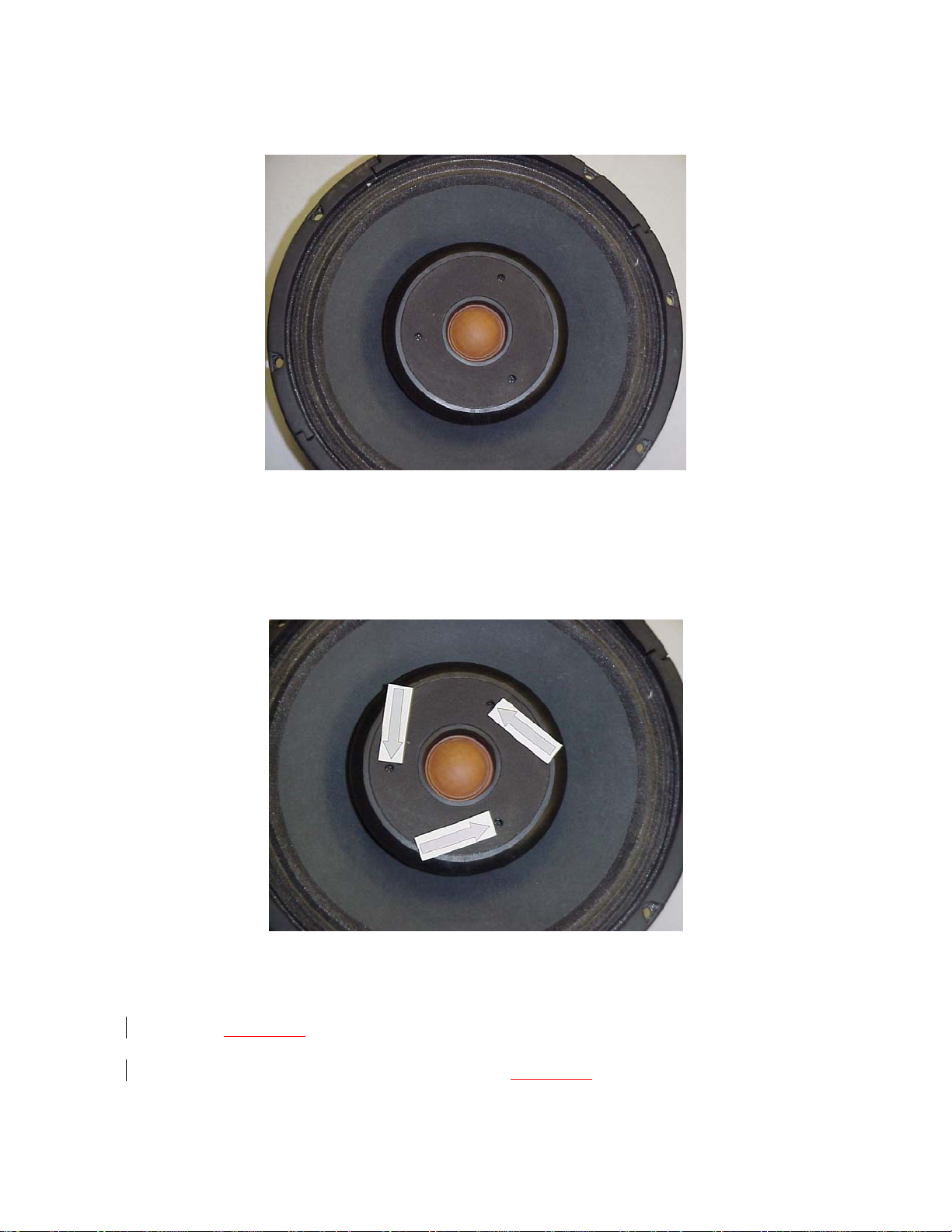
Figure 3
1. Place CD912-8A 12” Ceiling Speaker with Cone facing upward as shown in
Figure 3 on a clean, flat table.
Figure 4
2. Locate three (3) Philips Head screws (see Figure 4) that secure the Tweeter
Face Plate to the Tweeter Magnet.
3. Using a Philips Head Screw Driver remove the three (3) screws.
4. Carefully lift and remove the Tweeter Face Plate from the CD912-8A.
Page 3 of 11
Page 3
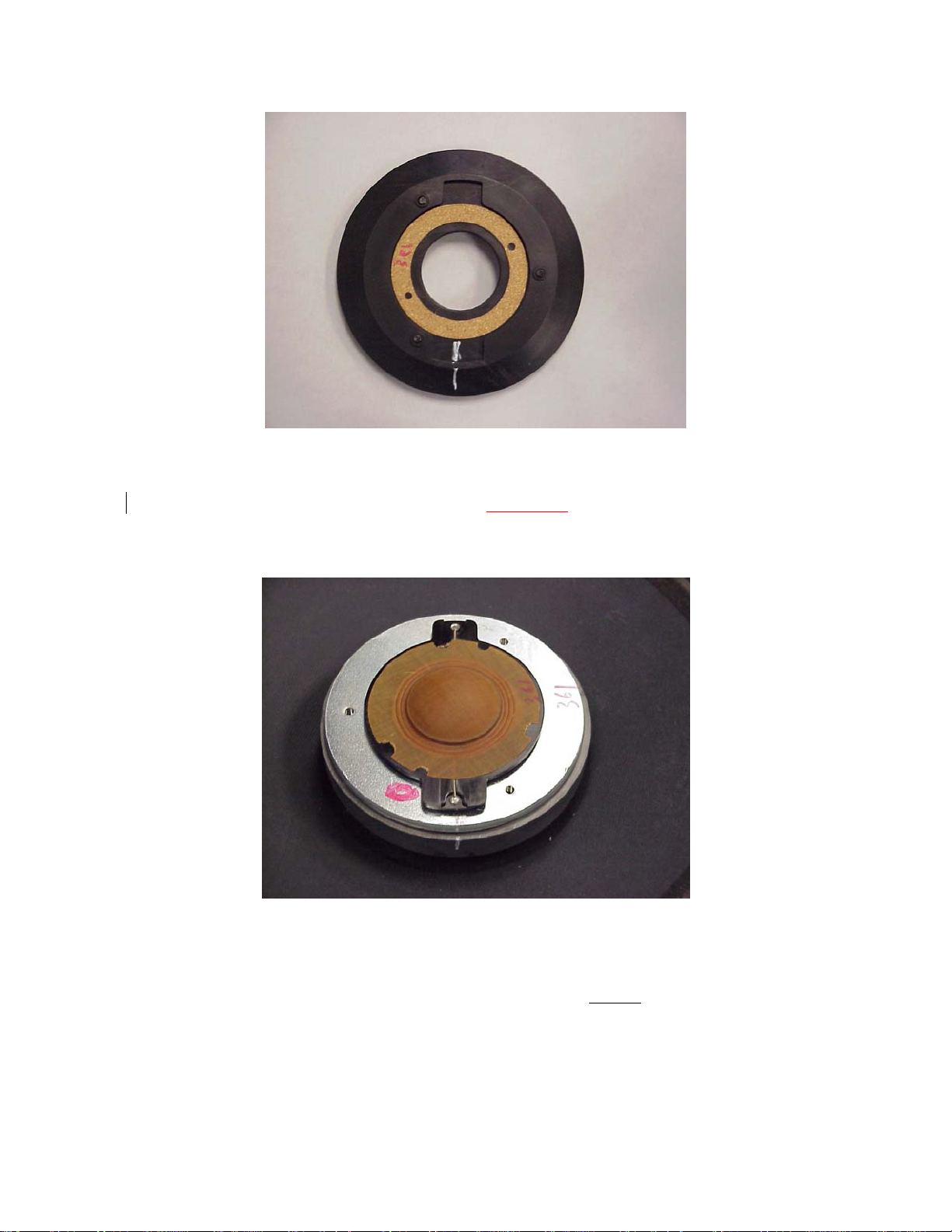
Figure 5
5. Note - the backside of the Tweeter Face Plate has a “keyed recess” into which
the Base of the High Frequency Voice Coil Assembly fits. This recess
contains a Cork Gasket. Take care not to damage the Cork Gasket.
Figure 6
6. Figure 4 illustrates typical markings that may be found on the Tweeter Magnet
and High Frequency Voice Coil Assembly. The critical marking(s) to be
aware of is associated with the High Frequency Voice Coil’s keyed Plastic
(Black) Base. Note the Red Circle and White Line shown in Figure 6. These
markings denote the Positive (+) Polarity of the High Frequency Voice Coil.
Page 4 of 11
Page 4

Figure 7
7. Note the two (2) ‘key ears’ of the High Frequency Voice Coil Assembly
contain Pin Terminals (see Figure 8) which are engaging mating Connectors
located in the Tweeter Magnet (see Figure 9).
8. Carefully insert a wide, thin Scraper (or wide, thin Screw Driver) between the
Tweeter Magnet and the High Frequency Voice Coil’s Plastic Base near the
Pin Terminals.
9. Gently rock the Scraper to apply an upward force (away from Magnet) to
disengage and lift the High Frequency Voice Coil’s Pin Terminal from its
mating Connector.
10. Repeat Steps 8 and 9 on the opposite side of the High Frequency Voice Coil’s
Plastic Base to disengage the second Pin Terminal.
11. Note Pin Terminals may not disengage without breaking, see Figures 8 and 9.
Page 5 of 11
Page 5

Figure 8
12. Figure 8 illustrates the bottom side of the High Frequency Voice Coil
Assembly. Note the right Pin Terminal is missing.
Figure 9
13. Arrow points to the missing High Frequency Voice Coil Assembly’s Pin
Terminal noted in Step 12. This Terminal Pin is still engaged to its mating
Connector.
Page 6 of 11
Page 6

Figure 10
14. Using a pair of fine Needle Nose Pliers, carefully grab the Pin Terminal
(Note - Tweeter Magnet will attract the Pliers) and gently twist the Pin
Terminal to break the adhesive bond.
15. Carefully pry upward to disengage and remove the Pin Terminal from its
mating Connector.
16. Take care not to grab the black plastic Insulator with the Pliers.
Figure 11
17. Figure 11 shows the High Frequency Voice Coil Assembly’s broken Pin
Terminal, after it has been removed from its mating Connector.
Page 7 of 11
Page 7
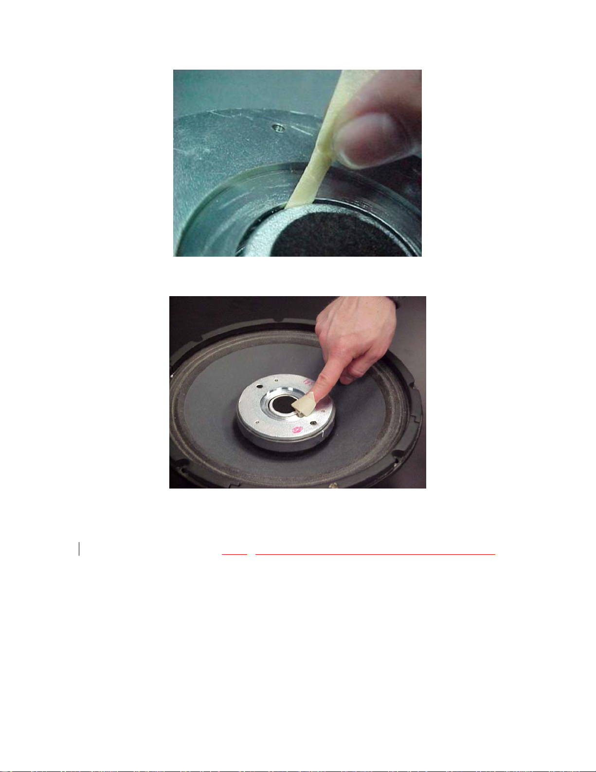
Figure 12a
Figure 12b
18. Clean Tweeter Magnet
Figures 12a and 12b.
’s gap with masking tape to insure it is free of debris.
Page 8 of 11
Page 8

Figure 13
19. Remove the replacement High Frequency Voice Coil Assembly from its
shipping box.
20. Note the Red Dot on the Voice Coil Former near the ‘wide key’ of the High
Frequency Voice Coil’s black plastic Base. This denotes the Positive (+)
Polarity of the Voice Coil and is critical for assembling correctly. Some
newer High Frequency Voice Coil Bases have a ‘+’ Symbol molded into the
plastic.
21. Make sure there are no foreign objects lodged within the High Frequency
Voice Coil Assembly.
Page 9 of 11
Page 9

Figure 14
22. Insert the two Pin Terminals of the replacement High Frequency Voice Coil
Assembly into their mating Connectors taking care to insure the correct
Polarity.
23. CAUTION - Be sure that the Pin Terminal of the ‘Wide Key’ is inserted into
the marked (Positive) mating Connector (see Figure 14).
24. Firmly apply pressure over both Pin Terminals to fully seat the High
Frequency Voice Coil Assembly. If properly inserted the Assembly will be
flush to the Tweeter Magnet’s surface.
Page 10 of 11
Page 10

Figure 15
25. Replace the Tweeter Face Plate taking care to insure its key recesses align
correctly with the High Frequency Voice Coil Assembly’s keys. Note Figure
15 shows a White mark on the Tweeter Frame aligning with the White mark
on the edge of the Tweeter Magnet.
Figure 16
26. Using a Philips Screw Diver tighten the three (3) Philips Screws to securely
fasten the Tweeter Face Plate
to the Tweeter Magnet.
Page 11 of 11
 Loading...