

Page 1

^ ■ \
9441A
Anniversary Series Power Amplifier
O pe r at i ng an d S e rv i ce In s tr u ct i on s
ALTEC LANSING® CORPORATION
n MARK IV coiiipiiiiy
P. O. Box 26105 © Oklahoma City, OK • 73126-0105 USA © Tel: (405) 324-5311 © FAX: (405) 324-89b1
Page 2

Operating and Service Instructions for the Altec Lansing 9441A Power Amplifier
Table of Contents
1 ELECTRICAL
1.1 120 V ac, 50/60 Hz Power Connection.«;........................................................................................... 1
1.2 220/240 V ac, 50/60 Hz Power Connections....................................................................................... 1
2 INSTALLATION.................................................................................................................................... 1
2.1 Eack Mounting .................................................................................................................................. 1
2.2 Ventilation ............................................................................................................................ . 1
3 SIGNAL CONNECTIONS...................................................................................................................... 2
3.1 Input Connections ............................................................................................................................. 2
3.2 Line Output Connections.................................................................................................................... 2
3.3 Output Connections........................................................................................................................... 2
3.4 Output Cable Selection....................................................................................................................... 2
3.4.1 Calculating Power Los.ses with 8 ohm Loads
3.4.2 Calculating Power Losses with 4 ohm Loads................................................................................. 2
3.5 Damping Factor.......................................................................................................................... . 2
3.5.1 Calculating the Maximum Length of Cable for a Specified Damping Factor
3.C Speaker Protection Fuse Selection ...................................................................................................... 5
3.7 Compros.sion Driver Protection Capacitors ........................................................................................... 5
4 OCTAL ACCESSORY SOCKETS
5 PROTECTION SYSTEMS .............................................................................................................. . . 5
5.1 Load Protection Circuitry..................................................................................................................... 5
5.2 Amplifier Protection Circuitry ............................................................................................................... 5
5.3 Protect Indicator........................................................................................................................ . . 6
......................................................................... ...........................................................
..................................................................................
...............................
. 3
‘ 1
2
G OPERATION......................................................................................................................................... 6
G.l Dual Mode of Operation............................................................................................................... . . 6
G.2 Bridge Mode of Operation ................................................................................................................... 6
7 IN CASE OF PROBLEMS
8 SPECIFICATION
9 SERVICE INFORMATION.................................................................................................................. 10
9.1 Equipment Needed......................................................................................................................... 11
9.2 Adjusting SVRl and SVR2, the BIAS Trimpots
9.3 Ordering Replacement Parts ..............................
9.4 Factory Service
9.5 Technical Assistance .........................................
...................
................................................
6
7
11
11
11
11
ALTEC JJCStSING^ CORPORATION o a Mar-k W Company
Page 3
Operating and Service Instructions for the Altec Lansing 9441A Power Amplifier
1 ELECTRICAL
Two amplifier models are
available. One model has a 50/60
Hz power transformer with two
120 V ac primary windings. These
windings may be wired in parallel
or series for operation at either
120 V ac or 220/240 V ac. The
other amplifier model is for export
into countries where tlie ac line
voltage is 100 volts, 50/60 Hz. The
next two sections refer to the first
model witli the dual 120 V ac pri
mary windings.
1.1 120 V ac, 50/60 Hz
Power Coimections
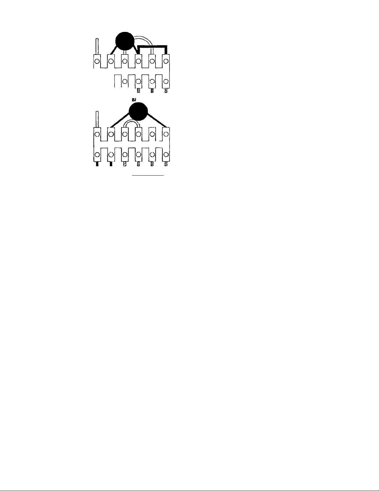
'rhe amplifier is provided
with the primary of the power
transformer slrappcil for 120 V ac
operation from the factory. Refer
to Figure 2 for the wirijjg deUiils.
WARNING: Verify that the power
transformer’s priinaiy circuit con
figuration is correct for the in
tended ac line voltage BEFORE
applying power to the amplifier.
1.2 220/240 V ac, 50/60 Hz
Power Connections
The power transformer
has two 120 volt primary windings
which can be connected in parallel
for 120 V ac line voltages, or in
series to meet 220/240 V ac re
quirements. Use the following
procetlures to re-strap the primary
of the power transformer for
220/240 V ac applications.
1. Malce sure the amplifier is
not connected to any
power source.
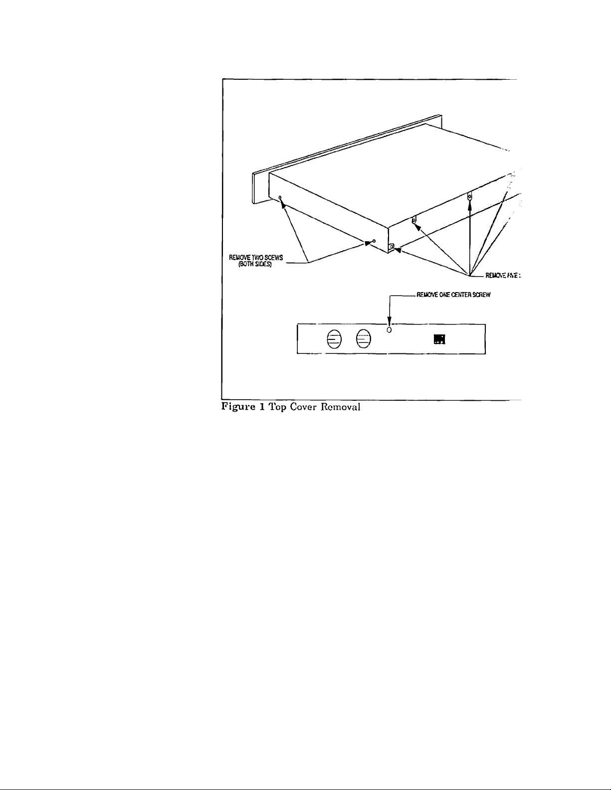
2. Remove and save the ten
screws securing the top
cover. Refer to Figure 1
for the exact screw loca
tions.
3. Locate terminal block TBl
located behind the AC
main power switch. Re
connect the leads as
shown in Figure 2.
4.
Install the top cover with
the ten screws previously
romovetl.
5.
Install the 2.0 A fuse,
T2.0A /250V slo-blo or
equivalent.
6.
Install the 230 Vac 50/-
60Hz and the T2.0A/250V
decals in the proper
positions.
INSTALLATION
2.1
Rack Mounting
The amplifier may be in
stalled in a standard 19 inch
equipment rack. It requires 1.75
inches of vortical rack space and
secures to the rack cabinet with
the-four rack mount screws and
cup washers provided in the hard
ware kit.
2.2 Ventilation
The amplifier m.;;;t be
adequately vontil.ntod tn ir.'oid ex
cessive temjjerature rise, i si;ould
not be used in areas where the
ambient temperature exceeds SO'C
(122°F). To determine i .imbient air temperature, opemte the
system in the rack until the tem
perature stabilizes. Mea'"ro the
ambient air with a bulb-type ther
mometer held at the botloin of the
uppermost amplifier. Dc tmt let
the thermometer touch the netal
chassis because the chassis will be
hotter than the ambient a:.-. If the
air temperature exceerls 50°C
(122°F), the equipment siiould be
spaced at least 1.75 inches apart
or a blower installed to provide
sufficient air movement within
the cabinet.
WARNING: Do not operate the
amplifier within a completely
closed unventilated housing.
ALTEC LANSING* CORPORATION • a Mark IV Company
Page 4
Operating and Service Instructions for the Altec Lansing 9441A Power Amplifier
For example, suppose an installer
uses 160 feet of 10 GA 2-wire
cable with an 8 H speaker system.
WHITE (A.a HECEPTAia^
The total po%ver loss in .U. cable
is;
A. 120 V ac Primary Wiring
X I ^
WHITE (A.C RECEPTACLE)
BIACK BUWHT BLUE
BLACK BLIWirr BLUE
_______________
nV/HT BROWN
8.240 V ac Primary Wiring
BRIWHT BROWN
Figure 2 Primaiy Wiring Configuration for 120 V ac and 220/240 V ac
SIGNAL CONNEC
TIONS
3.1
Input Connection.s
Balanced input connec
tions may be made to either the
Va phono (TRS) or the female
XLR connectors. For single-ended
inputs, strap the low (—) input to
ment. Refer to Figure 3 for po.ssi-
ble applications.
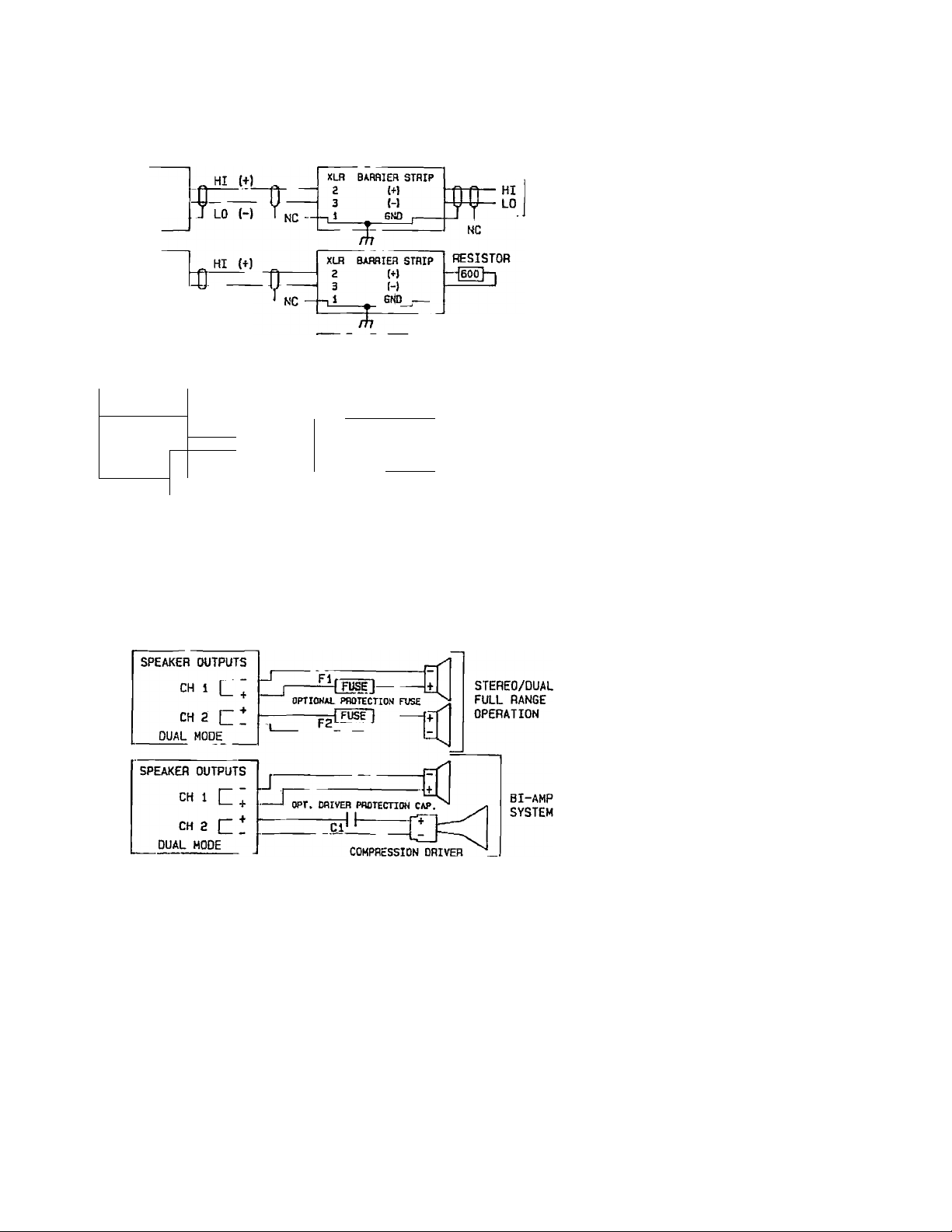
3.3 Output Connections
Output connections are
made to the four terminal barrier
strip connector located on the rear
of the unit. Refer to Figure 4 for
tj'pical output connections.
ground (pin 3 on XLR or Ring on
Va" phone). Otherwise, the elect
ronically-balanced input stage will
see 6 dB loss input signal level
than with a balanced input. Refer
to Figure 3 for typical input con
nections.
3.4 Output Cable Selection
Speaker wire size plays an
important part in quality sound
systems. Small wire gauges can
waste power and reduce the
damjiing factor at the speaker
terminals. This can add coloration
3.2 Line Output Connec
tions
TliD XLR and Vi" phone
connectors are wired in parallel.
Pin 2 of the XLR is the Tip of the
and muddincss to the sound. To
help offset this problem. Table I
has been assembled to enable you
to calculate the power losses in
the speaker cable.
Va" phono comiector, and pin 3 is
the Ring. Since the input imped
ance of the electronically-balanced
input stage is high (15 kohms),
there is minimal loading on the
signal source, Wien the input
connections are made to one con
nector, the other may be used as
an auxiliary line output to feed
other high input impedance equip
3.4.1 Calculating Power
Losses with 8 ohm
Loads
To calculate the total
power loss in the spealcer cable,
multiply the power loss per foot
(or meter) of the 2-wire cable sel
ected from Table 1 by the length
of the cable in feet (or meters).
Total Power Loss in cable
= 0.0191 watts/foot X lOr feet
= 3.0 watts
Does this mean that whena er the
amplifier produces 75 walls of
output power, 72.0 watts (75 watts
minus 3.0 watts) will be delivered
to the 8 ohm load? N'^d The
actual load impedance is ohms
plus the resistance of Iht cable
(0.00204 ohms/foot times L'"' feet)
for a total load imped.nice of
8.3264 ohms. At the 8 lated
output power, the output, /oltage
is 24.4 V rms. Therefore, I t ■ amp
lifier produces 71.5 wati - with
this load instead of 75 wa.‘ . This
was calculated by squaring the
voltage and dividing by I load
impedance (24.4* divid. i by
8.3264 ohms). As a result, ue act
ual power delivered to thf !-ad is
68.5 watts (71.5 watts minus 3.0
watts).
Had 18 GA wire been used hi the
above example, the lass in the
cable would have been Ifl.r ivatts.
Tliis example lllustrale.s I im
portance of using the pro; . wire
size.
3.4.2 Calculating <wer
Losses with 4 ohm
Loads
To calculate the- i sses
when using a 4 ohm speak .-; os
tein, multiply the loss at hms
by 3. In the above exampk-. the 10
GA wire would consume 9,'' watts
of power while the 18 GA '.■.•ire
would waste 58.5 watts more
than half of the amplifier’’^ ohm
power rating.
3.5 Damping Factor
The higher the da aping
factor rating of an amplill'-!' the
greater the ability of the am; lifier
A1.TEC lANSING' CORPORATION * a Mark T\' Company
Page 5
Operating and Service Instructions for the Altec Lansing 9441A Power Amplifier
inward but its niomontum cmises
it to overshoot its resting point.
SOURCE AMPLIFIER'S INPUTS
BALANCED
SOURCE
BALANCH3
SOURCE
H/600 OHM
TERMINATION
UNBALANCED
SOURCE
------------
UNBALANCED
SOURCE
/, 1
LO (-)
HOT
HOT
J COM
'G j
r
NC
Figure 3 Topical Input Connections
SINGLE-ENDEO AUX OUTPUT
XLn BAFIflIEH STRIP
2 (+)
3 (-)
6Ю ¡-
7lr ^
ЯЛ
ВАИЙ1ЕП STHIP
2
Э
—t i
(t)
H
E.ND ,
%
Ж.
-----
AUX OUTPUTS
(USER OPTIONS)
BAL
OUTPUT
HOT
KEEP
COM
CABLE
RUNS
UNDER
6 ft
HOT
OR 2 m
COM
NC
This overshoot will dampen itself
out eventually but the unwanted
movements can add consitlerable
distortion products to tlu touiul.
In the process of moving hv.vard
through the magnetic fieUh the
voice coil assembly generatos a
current of opposite polarity tn the
original signal. This current in
duces a voltage or "back EMF”
which travels through the speaker
wire to the amplifier's '.utput.
The lower the amplifier’i. output
impedance, the faster tl.o overslioot of the voice coil will dampen
out. The output impedii'io; of an
amplifier can be calculated by
dividing the rated output linped-
ancG, typically 8 ohms, uy the
damping factor. The 944 i A has a
damping factor rating ; 100
which corresponds to an 4Utput
impedance of 0.08 ohni.s.
AMPLIFIER'S OUTPUTS
SPEAKER OUTPUTS
CH 1 L‘
eniOGE OUTPUT Q I I
CH г
BRIDGE MODE
Figure 4 'Topical Output Connections
to control unwanted speiiker cone
movements. When a signal drives
a woofer, current flowing through
the voice coil creates a magnetic
field. This field interacts with the
LOUDSPEAKER LOADS
HIGH POWER
FULL RANGE/
=0]
SUBWOOFER
permanent magnetic field in the
gap and forces tlie combination
cone and voice coil assembly to
move outward. When the signal is
removed, the assembly moves
3.5.1 Calculating the
Maximum Length of
Cable for a Spenified
Damping Factor Spec
ification at the Load
Tlie damping factor rating
is typically never realiz-т-: at the
load because of the rosisLunce of
the cable (and other facLnia such
as the contact resistance of an
output relay or the resistance of
an output fuse). Tlie damping fac
tor at the load should be 30 for
general paging systems ami 50 for
high fidelity music systcm.s. Econ
omics usually dictate, however,
that these numbers are cut-in
half. The resulting dampiiig factor
at the load should be based on ex
perience and customer satis
faction. Once a minimum; c ciiiping
factor is determined for => partic
ular type of installation, the fol
lowing equation can calculate the
maximum length of 2-wire cable
which can be used to achieve the
minimum damping factor .s^x cified
at the load:
ALTEC LANSING* CORPORATION • a Mark TV Company
Page 6
Operating and Service Instructions for the Altec Lansing 9441A Power Amplifier
Max. Length of 2-wire cable in
feet
ZL — Zo
= DF
DCR/ft
where
ZL is thé load impedance
to comiect to the amp
lifier;
Zo is the amplifier’s out
put impedance (0.08 ohms
for the 944lA);
DF is the minimum permi.ssible damping factor at
tlie load; and
DCR/ft i.s the DC resis
tance of the 2-wire cable
per foot from Table I.
The same equation can be used to
calculate the maximum cable
length in meters by substituting
the DCR per meter value from
Table I.
Let’s use the equation. Suppose
ZL equals 8 ohms, Zo = 0.08
ohms, and the minimum damping
factor at tlic load is 25. In addi
tion, IS GA cable is preferred.
Then, the maxiinxim length of 18
GA cable which can be used to
achieve a damping factor of 25 fit
the load is;
8
25
(0.08)
IS.4 feet
0.01302 n/ft
Table I 9441A Power Losses in 2-wire Speaker Cable
Power
AWC, nc:n/fi I.ciss/n Socllonal UCR/iTicler I^ishKlcr
(0Л) (îVil) (willt.s/(1)
G 0.Ü0Û8I
8 0.00121 0.0i:)4 8.30 0.0042I 0.0394
10
12
И
IG
18 0.01302 0.1218 0.82
20 0.02070 0.1935
22
0.0020'!
0.00324
O.OO.'il.'i 0.0482
0.0081!)
0.03202 0.:t073
0.0075
0.0191
0.0303 3.31
0.0767
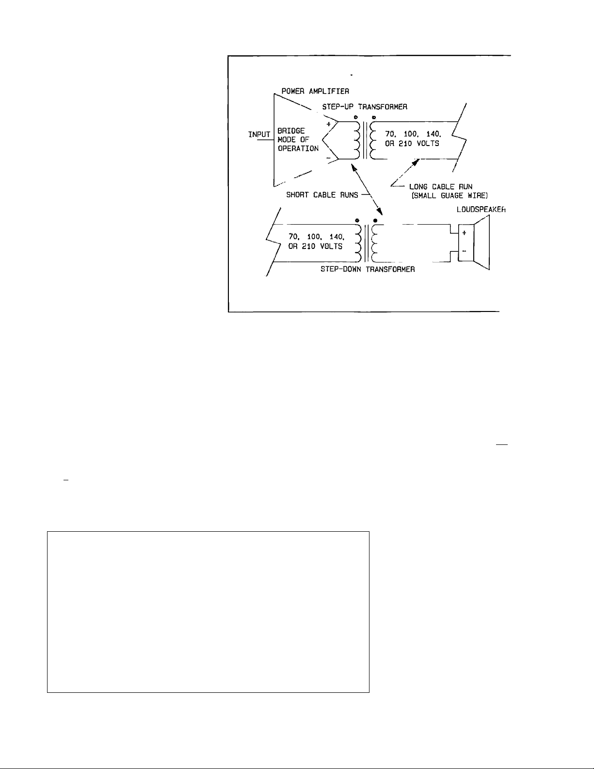
Figure 5 High-voltage Distribution System
Sometimes it may be necessarj' to
locate the speaker 100 feet or
more away from the amplifier. In
this situation, a much larger
gauge cable is required. However,
this may not be jiractical or eco
nomical. The size of the 2-wire
cable can be greatly reduced by
stepping up the output voltage of
tlie amplifier to 70, 100, 140, or
210 volt, using an output trans
former, then stepping down the
voltage at the load. Such a system
is shown in Figure 5.
Cable Crossarea (iiim*) (U/m)
13.30 0.00204
5.26 0.00669
2.08 0.01691
I.3I 0.02085 0.2508
0.52
0.33 0.10658
0.01063 0.0052
0.042S9 0.39Î16
0.06764 0.6288
Power
(woUs,/m)
0.0247
0.0626
0.1581
0.9860
I'he maximum
cable in this situation can be
approximated from the following
equation:
Max. Length of 2-wire o;
feet
(Pout)(DCR./ft)
where
V is the stejipod-up
voltage of the system;
Pout is the rated output
power of the amidifier;
Zo is the output imfiedance of the amplifier (0.08
ohms for the 9441A r,
ZL is the load impeo.mce;
DCR/ft is tb. DC
resistance of th: 2-wire
cable per foot from Table
I; and
DF is the minimum
permissible damping fac
tor at the load.
length of v-v/ire
ie in
Zo
J_
ZJ.
DF
ALTEC LANSING* CORPORATION © a Mark IV Company
Page 7

Operating and Service Instructions for the Altec Lansing 9441A Power Amplifier
Suppose a 210 volt system were
used at a 200 watt power level to
drive an 8 ohm load with a mini
mum damping factor of 25. Using
the same 18 GA cable as before,
the maximum length can now be
508 feet. Power companies use
this technique to transfer large
amounts of power over great dis
tances.
3.6 Speaker Protection
Fuse Selection
Sometimes it may be de
sirable to use in-line fuses (fuses
in series with the output) to pro
tect loud-sixjakor s3 'stems (or the
ampIirieiO- It is difficult, however,
todotermino the proper fuse value
with the correct lime lag and
overload cliaracteristics to match
the limitations of a speaker sj’stem. The values shown in Table II
should serve only as a guide. To
use, determine the power rating
and load value. Then, select a
standard value fuse of the next
smaller value to the one listed in
tlie table.
The values are calculated for fastblow fuses which carry 135% of
their current rating for an liour
but will blow within 1 second at
200%. Other fuse values may be
calculated for different power
levels from the following equation:
Fuse value =
(Pout X ZL)^ amps
ZL X 1.35
where
Pout is the output power
rating of the amplifier;
and
ZL is the load impedance.
Use 32 volt fuses if possible; they
typically have the lowest internal
resistance which will help nnnimize deterioration of the damping
factor at the load. Refer to the
example in Figure 4.
Table II Calculated Output Fuse
Values
Power 1 a 8П ion
(4Villl.s)
100 3.70 2.02 1.85
l-TO 3.21 2.27
200 5.2-1 3.70 2.02
3(X1 0.-12
400 7.-11
000
bond
0.07
LoafI
■-1..5-1 3.21
5.2-1
0.42
l.o.-)(l
3.70
4.5-1
3.7 Compression Driver
Protection Capacitors
Compression drivers, u.sed
for mid to high frequency sound
reproduction, are much more sus
ceptible lo damage from low' fre
quencies than large cone loud
speakers. Even though an elec
tronic crossover may be cmploj’od,
problems may arise in the cables
between the cros.sover and the
power amplifier, or from misadjustment of the cros.sover.
Either of those situations could
apply low frequency signals or
hum to the driver and cause
damage. To prevent a potential
mishap, Altec Lansing recom
mends using a capacitor between
the amplifier and the compression
driver to suppre.ss low frequencies
and possible DC. Refer to the
example in Figure 4.
In choosing a value, one must be
careful not lo interfere with the
crossover frequency. As a general
rule, select a capacitor whose
break frequency, with respect to the
load, is 3 dB down at approxi
mately Vu of the high pass comer
frequency.
Table III Compression
Driver
Protection Capacitors
Crossover 3 fl ion
Frequency Driver Driver
500 llz 80 |iF 40 iiF
800 llz 50 цР 25 iiF
1000 Hz 40 III1250 Hz
2000 Hz
3150 Hz 12 tiK
33 >iF 10 pF
20 tiF 10 |aF
20 tiF
6 (iF
Mylar capacitors with ai !st a
100 volt ac rating are -om-
mended. Table III show.: ;e re
commended capacitor val ;; for
use with 8 and 16 olnn dr’ ', rs at
popular crossover frequoucie.';.
4 OCTAL ACCES ORY
SOCKETS
Two octal sockets ¡i' ^rnita
variety of plug-in accessc.rii’n to be
used w'ith the amplifier. Uoi ...ally,
one “U" jumper is ins(-r'- be
tween octal socket pins : ,;d 1,
and another between pins " nid 6.
These jumpers must re;;:. ■; in.
place for the amplifier to .'rate
when not using any . : sorj
modules. To use with an ac .soiy
module, remove (and sr.- -- the
jumpers and install the . ulule
making sure the key on it ■ ■ .'nter
post aligns with the groove- ’ . the
female socket. For operation, refer
to the instructions provide d with
the modulo. Schematically the
module will be inserted '■ r.ween
the input connector and - bal
anced input stage.
Electronic modules are ; ... red
from a bipolar 15 volt su ily in
the amplifier. The sxij-: : is
capable of supplying up to 25 ma
DC of current. Currents ¡¡. i:;;icess
of 25 ma DC may prevent Li; ■ amp
lifier from disengaging :n its
built-in protection mecha:;’ .as.
5 PROTECTION SYS
TEMS
5.1 Load P rote: ’on
Circuiti'y
Each channel ind yend-
ently protects its load from
startup/shutdown transir>n'-DC,
and large subsonic signals.
5.2 Amplifier Protc-otion
Cii'cuitry
A unique current-lL.dling
circuit was designed specifically
for the amplifier. It feat .es a
variable current limit whic! is a
ALTEC LANSING^ CORPORATION * a Mark TV Company
Page 8

Operating and Service Instructions for the Altec Lansing 9441A Power Amplifier
function of the output signal vol
tage. As a result, the amplifier can
deliver the rated currents into
rated loads but substantially
limits the current into low imped
ance or shorted loads (shorted
output terminals). Once the short
is removed, however, the amplifier
will resume normal operation.
The heatsink is conventionally
cooled. Slioxild the heatsink
temperature of a channel remain
excessively high, both chamiels
will .shut down automatically.
Wien the output devices cool to a
safe operating temperature, the
channels will automatically re
sume normal operation.
5.3 Protect Indicator
I'he “PROTECT” LED
illuminates when either channel
enters thermal protection. If a
shutdown does occur, the chan
nels will resume normal operation
as soon as its devices have cooled
to an acceptable temperature.
If the protection LED illuminates
and there is no indication of ex
cessive temperature, one, or both,
of the channels is in an internal
fault mode. If this occurs, refer to
the service instructions on page
12.
G OPERATION
G.l Dual Mode of
Operation
In the dual mode of opera
tion, the channels may be
operated independently. After in
stallation and hookup, verify that
the mode switch, located on the
rear panel, is in the “DUAL” posi
tion and rotate the level controls
fully counterclockwise (full atten
uation). Input a 0 dBu (0.775 V
rms) nominal signal level and
apply power. Slowly increase the
level controls until the desired
output power is obtained. If either
“CLIP” LED illuminates, reduce
the outjnit with the channel level
control or reduce the input signal
level at its source.
WARNING: Never attempt to con
nect the outputs of the two chan
nels in parallel.
6.2 Bridge Mode of
Operation
After installation and
hookup, verify that the mode
switch, located on the rear panel,
is in the “BRIDGE” position.
Rotate both levels controls fully
counterclockwise (full attenua
tion). Input a 0 dBu (0.775 V rms)
nominal signal level into channel
1 only and apply power. Slowly in
crease the level control of channel
1 until the desired output power
is obtained. If either “CLIP” LED
illuminates, reduce the output
level with the level control or re
duce the input signal level at its
soiirce.
CAUTION: Be sure that no input
connections are made to channel 2
and that its level control is fully
counterclockwise (OFF).
WARNING: The bridged output
mode provides a true halariced-to-
ground output. Do not use any test
equipment to test or evaluate tins
amplifier which does not have
floating grounds.
In Case of Problems
Please check the following
items:
1.
Verify that tlie amplifier
is properly coimected to
an ac power source and
that the source is active.
2.
Verify that the input
connections are properly
made. Refer to Figure 3.
3.
Verify that the output
comiections are properly
made. Refer to Figure 4.
4.
Check the input and out
put cables for proper
‘ wiring and continuity,
5. Check the signal source
and the load.
6. Ensure that the two
jumpers for each octal
socket are properly in
stalled (if not using op
tional plug-in modides).
7. Ensure that any aece.ssory
modules installed do not
draw more than i'u ma
DC of current.
8. Check that the mode
switch is in tin; •' :ured
position.
NOTICE: Repairs performed, by
other than authorized wananiy
stations (Dealers) or q: 'ified
personnel shall void the ivm—anty
period of this unit. To avoid loss
of warranty, see your neare;-; Altec
Lansing authorized dealer, or call
Altec Lansing Customer e-ervice
directly at (405) 324-531' Fc\X
(405) 324-8981, or write:
Altcc Lansing Customei
Sciwice/Repair
10500 W. Reno
Oklahoma City, OK 73128
U.S.A.
AIAEC LANSING^ CORPORATION o o Mark T\^ Company
Page 9

operating and Service Instructions for the Altec Lansing 944lA Power Amplifier
8
Conditions:
1. 0 dBu = 0.775 volts rins.
2. Dual mode ratings are for each channel.
3. Both channels operating at rated output power
4. 120 volt ac line input voltage maintained for all
Continuous Rated Output Power:
(20 IIz - 20 kHz at less than 0.1% THD)
Dual mode, 4 fi; 100 watts/ch
Bridge mode, 8 fl: 200 watts
Dual mode, 8 fl; 75 watt..s/ch
Bridge mode, 16 Cl: 150 watts
Continuous Rated Output Pow'er to Subwoofer:
(20 llz - 1 kHz at less than 0.1% TIID)
Dual mode, 4 0: 130 watts/ch
Bridge mode, 8 O: 260 watts
Dual mode, 8 O: 95 watts/ch
Bridge mode, 16 O: 180 watts
Miiximum Midband Output Power:
(Ref. 1 kllz, 1% TIID, @120 volts ac line voltage)
Dual mode, 4 O:
Bridge mode, 8 O:
Dual mode, 8 O:
Bridge mode, 16 0:
(Ref. 1 kHz, 1% THD, @108 volts ac (10% sag))
Dual mode, 4 O:
Bridge mode, 8 O:
Dual mode, 8 O:
Bridge mode, 16 O:
SPECIFICATIONS
unless noted.
tests unless noted.
>145 watts/ch
>270 watts
>100 watts/ch
>200 watts
>115 watl.s/ch
>220 watts
> 80 watts/ch
>155 watts
Voltage Gain:
(Ref. 1 kHz)
Dual mode, 4 fl: 28 dB
Dual mode, 8 Cl: 30 dB
Bridge mode, 8 fl: 34 dB
Bridge mode, 16 fl: 36 dB
Input Sensitivity for Rated Output Powci-
(Ref. 1 kllz, ±0.5 dB)
Dual mode, 4 fl:
Bridge mode, 8 fl:
Dual mode, 8 fl:
Bridge mode, 16 ft:
Miiximum Input Level:
(Ref. 1 kHz)
Input Impedance:
(Ref. 1 kHz)
Balanced:
Unbalanced:
Polarity:
Phase Response:
(Any mode)
20 Hz:
20 kHz:
THD: <0.1% aVp. <0.05%)
(Any mode, 30 kHz measurement bandwidth i
OdBu (0.774 V - ' s)
-0.25 dBu (0.752 v rms)
+1.0 dBu (0.869 V .rms)
+ 1.0 dBu (0.869 ” rms)
+20 dBu (7.75 V . ms)
30 kfl
15 kfl
Positive-going signal
applied to pin 2 of TvLR
or (+) of */«" phone (tip)
produces positive-going
signal at (+) output
terminal.
<+25°
>—25°
(Ref. 1 kHz, 1% THD, @100 volts ac (17% sag))
Dual mode, 4 Cl:
Bridge mode, 8 fl;.
Dual mode, 8 fl:
Bridge mode, 16 fl:
Headroom (Before clip): >1 dB
(Ref. 1 kHz, 1% TIID, single channel mode)
Frequency Response: 10 Hz - 50 kHz
(Ref. 1 kHz, 1 watt output, +0/—3 dB)
Power Bandwidth; 20 Hz - 20 kHz
(Ref. 1 kHz, +0/—1 dBr where 0 dBr = rated output
power in any mode)
> 95 watts/ch
>185 watts
> 70 watts/ch
>135 watts
ALTEC LANSING'^ CORPORATION » « Mark IV Company
IMD (SMPTE 4:1);
(Any mode)
Slew Rate:
Dual mode, 4 or 8 il:
Bridge mode, 8 or 16 fl:
Damping Factor:
(Dual mode, 8 fl)
1 kHz:
(Ref. 1 kHz, 0 dBr = rated output power into 8
ohms, single channel operating)
Noise; > 100 dB
(Below rated output power, A-weighting filter, 8 fl
dual mode, 50/60 Hz ac line frequency)
<0.1%
>19 V/psec
>37 V/psec
>100
<55 dBrCrosstalk:
Page 10

Operating and Service Instructions for the Altec Lansing 9441A Power Amplifier
Amplifier Protection;
Load Protection:
Cooling:
Hea(.sink:
Output Topology:
Output TVp®'
Dual mode:
Bridge mode:
Output Devices:
Total number:
Pdmax rating:
Vceo:
Ic:
Tjmax:
Controls and Switches:
Front:
Rear:
Front Panel Indicators:
Shorted output term
inals, Over-temperature,
RF interference
Startup/shutdown trans
ients, DC faults. Sub
sonic signals
Conventional heatsink
True complementary
symmetry
Unbalanced, each chan
nel
Balanced
4 devices
130 watts
180 volts DC
15 amps DC
150 “C
Two input level controls.
Power switch
Mode switch
Power LED, Clip LED (x
2), Protect LED
Operating ac Voltage
Range: Operates from line
voltages as low as 90
volts (at reduced output
power) assuminf; = 120 V
ac nominal line.
Power Consumption/
Heat Produced:
(Both channels operating in dual mode wit!- i kHz
sinewave input signal at slated output power into 4
Cl loads)
idle:
30 watts/0.102 kBTU/h
l/8lh max
midband power:
270 watts/0.833 kBTU/h
l/3rd max
midband power:
390 watts/1.099 kliTU/h
Rated output power: 600 walts/1.360 kBTU/h
Max midband power: 730 watts/1.490 kB'f'UAi
Opei'ating Temperature
Range;
Up to бО^С 122“F)
ambient
Dimensions (Rear of rack cars to max depth):
1.75 in II X 19 in W X
12.8 in D
(4.44 cm II X 48.26 cm W
X 32.51 cm D)
Connections;
Input:
Output:
Power:
Fuse Tjpe:
Power Requirements:
'// phone (x 2),
Female XLR (x 2),
Octal accessory socket (x
2), powered with ±15
volts DC at 25 ma.
Barrier strip
6 ft (1.83 m), 3-wire, 18
GA power cord with
NEMA 5-15 plug/IEC
T 4 A/250 V Slo-Blo or
equivalent (for 120 Vac
use)
120 Vac, 50/60HZ, 300
watts (configurable to
220/240 Vac). 100 Vac.
50/60 Hz model avail
able.
Shipping Weight:
Net Weight:
Color:
Enclosure;
Standard Accessories:
22 lbs (9.97 kg)
18 lbs (8.16 kg)
Black
Rack mount chassis, 16
GA steel, 3/16 i:; 5052
aluminum alloy front
panel
4 - “U” jumper idugs for
octal sockets '3 per
socket, installetl'
1 - Operating instruct
ions mid Service Manual
1 - 1'2 A/250 V ni.se (for
220/240 V ac '
ALTEC LANSING^ CORPORATION o a Mark TV Company
Page 11

Operating and Service Instructions for the Altec Lansing 9441A Power Amplifier
Optional Accessories:
1^9 )V
Power Limiter
put Bridging
mer
15515A Input Bridging
Transformer with Pad
15170 100 watt Auto
former
* 15581A 24 dB/oct
Li nkwitz-Riley Crossover
15594A-XXX 18 dB/oct
Low Pass Filters
15595A-XXX 18 dB/oct
High Pass Filters
15509A Bass Boost
module
The “-xxx” represents various corner frequencies
available for the corresponding filter.
* Note: Tlie 14712A, and the 15581A will
extend above and below the back panel
0.625 inches (1.58 cm).
ALTEC LANSING CORPORATION continually
strives to improve products and performance.
Tlierefore, the specifications are subject to ch.mge
witliout notice.
V
ALTEC LANSING* CORPORATION • a Mark IV Company
Page 12

Operating and Service Instructions for the Altec Lansing 9441A Power Amplifier
off
9441A Power Amplifier
SERVICE INSTRUCTIONS
* * * CAUTION * * *
NO USER SERVICEABLE PARTS INSIDE. EXTREMELY ILAZARDOUS VOLTAGES AND CURRENTS MAY BE ENCOUNTERED
WITHIN THE CHASSIS. THE SERVICING INFORMATION CON
TAINED \VITHIN THIS DOCUMENT IS ONLY FOR USE BY ALTEC
LANSING AUTHORIZED WARRANTY REPAIR STATIONS AND
QUALIFIED SERVICE PERSONNEL. TO AVOID ELECTRIC
SHOCK, DO NOT PERFORM ANY SERVICING OTHER THAN THAT
CONTAINED IN THE OPERATING INSTRUCTIONS UNLESS YOU
ARE QUALIFIED TO DO SO. OTHERWISE, REFER ALL SER
VICING TO QUALIFIED SERVICE PERSONNEL.
10
ALTEC LANSING* CORPORATION o a Mark IV Company
Page 13

Operating and Service Instructions for the Altec Lansing 9441A Power Amplifier
9 SERVICE INFORM
ATION
WARNING; No user serviceable
parts inside. Extremely hazardous
voltages and currents may be en
countered within the chassis. The
servicing information contained
within this document is only for
use by Altec iMusing authorized
warranty repair stations and
qualiped service personnel. To
avoid electric shock DO NOT per
form any servicing other than that
contained in the Operating Instr
uctions unless you are qualified to
do so. Otherwise, refer all servi
cing to qualified senice personnel.
NOTICE: Modifications to Altec
Lansing products are not recom
mended. Such modifications shall
be at the sole expense of the
pcrson(s) or company responsible,
and any damage resulting there
from shall not be covered under
warranty or otherwise.
9.2 Equipment Needocl
To precisely adjust the
trimpots, you must have tlie fol
lowing equipment:
1 — Digital DC volt meter
2 — 4 Cl load rated at 200
watts
1 — Small non-conducting
flat-blade screwdriver or
set of plastic TV
alignment tools
Miscellaireous handtools
(to remove the top cover)
NOTE; If you need to verify the
amplifier's performance against
the rated specipcations, you must
be able to maintain the ac line
voltage constant at 120 V ac (or
240 V ac if wired according to
Figure 2). Therefore, we recom
mend a suitably rated variac (50
ampere rating at 120 V ac).
9.2 Adjusting VR02 and
VR102, the BIAS
Trimpot
To adjust VR02 and VR102 for
the proper bias, follow the pro
cedures below:
1. Turn power off and dis
connect the unit from its
power source. Make sure
the unit is in the Dual
mode with 4 D loads con
nected to each channel.
2. Remove the ten screws se
curing the top cover.
Refer to Figure 1 for the
.screw locations.
3. Channel 1: Locate the
junction of Ql2’s emitter
and R37. Connect the pos
itive side of the digital DC
volt meter to the junction
of QI2’s emitter and R37.
Then locate the junction
of Ql4’s emitter and R38.
Connect the negative side
of the digital DC volt
meter to the junction of
Ql4’s emitter and R38.
Connect the unit to its
power source and turn the
power on. Adjust VR02 so
that the digital DC volt
meter reads 7 milli volts
DC (± .2 mVdc). Turn
power off and disconnect
the unit from its power
source.
Note; Adjust Bias im
mediately after turning
power on.
4. Channel 2: Locate the
junction of Qll2’s emitter
and R137. Connect the
positive side of the digital
DC volt meter to the
junction of Q112’s emitter
and R137. Tlien locate
the junction of Qll4’s
emitter and R138.
Connect the negative side
of the digital DC volt
meter to the junction of
Qll4’s emitter and R138.
Connect the unit to its
power source and turn the
power on. Adjust VR102
so that the digiUiI DC volt
meter reads 7 milli volts
DC (± .2 mVdc). furn
power off and disc'.'iinect
the unit from its pow'er
source.
Note: Adjust r.ias im
mediately after Lii ruing
power on.
0
Re-install the lop cover
.
with the ten screws pre
viously removed.
9.7
Oi'ilex'ing Replacement
Parts
To order replacvinent
parts, look up the <r.lering
number from the componen, parts
listing and call (405) 32-5-531L,
FAX (405) 324-8981, or wrih-:
Altec I.ansing
Replacement Parts Sales
P.O. Box 26105
Oldahoma City, OK 73120-0105
9.8 Factory Service
If factory ser\ ice is
required, ship the unit ;;i its
original packing prepaid tv
Altec Lansing Customer
Service/Repair
10500 W. Reno
Oklalioma City, OK 73128
Enclose a note describing the pro
blem in as much detail as possible.
Include any additional helpful in
formation such as test conditions,
where used, how used, etc,
9.9 Technical Assisi anee
For applications assistance
or other technical information,
contact the Technical Services
Manager. You can call (405) 3245311, FAX (405) 324-8981, or
write:
Altec Lansing
Technical Services Manager
P.O. Box 26105
Oklalioma City, OK 73126-0105
ALTEC LANSING'^ CORPORATION • a Mark IV Company
11
Page 14

Operating and Service Instructions for the Altec Lansing 9441A Power Amplifier
r
J02p4-(i> ^
JOI
JD2r
‘ I» .
Jtot
V'-
Ao
f«s 3’
<?>X JKJ3 0>
^ <*)
y IV.
S’-
IV,
r^IV.
•['«') —I
I C I0> nPCCE M'Xir
m
SW7
prtS—
5JJt%
tS^II
M-ThV
A c<ut top| .
0Ù? a>.'>
A'»TOW •?
«• ‘'■4 -■{
:^>\d
lip ^
KJO I
1
I ip
«£««1
Ziri"
I C*) *
«K1V. ^r,..., ,,
-1 - . I
Bi* 2i/n
-Wi?5}—
8?0* IV.
Sag ¿Y"-;
rt u *
CM?
11 i
II
¡■il
25
ite
----
12
!.v
-<^Y\
CK*I
H \—
tt*0*
♦ DV
<
(I')
<
Figure 6 Schematic of 9441A, Sheet 1 of 2
ALTEC LANSING* CORPORATION ® a Mark IV Company
jW
w
©
©
l3V/\
itr iV.
1 • -5K
OMT
■ _ } r T ^
"*3,0 '
gT77.'
•a
■o^N
A8MT I
iVM
fl!
to:
Page 15

operating and Service Instructions for the Altec Lansing 9441A Power Amplifier
__
Figure 7 Schematic of 9441A, Sheet 2 of 2
ALTEC LANSING* CORPORATION • a Mark IV Company
13
Page 16

operating and Service Instructions for the Altec Lansing 9441A Power Amplifier
Component Parts Listing for the 9441A
Reference Ordering
Designator Number
Name and Description
(
ROl, R02, RlOl, R102 47-03-121532
R03, R103 47-03-122803
R04-07, R104-107 47-03-028238
R08, R108 47-03-037660
R09, R109 47-01-028011
RIO, RllO, 47-01-028530
Rll, R25, Rll, R125 47-01-102072
R12, R44, R45, R47, R51, 47-01-102106
R112, R144, R145, R147, R151,
R203
R13, R113 47-03-028274
R14, R30, R114, R130 47-01-102112
R15, R18, R115. R118 47-01-102080
R16, R19, R116, R119 47-01-102054
R17, R28, R32, R117, R128, 47-03-038030
R132
R20, R33, R120, R133 47-03-028694
R21, R121, 47-03-038031
R22, R122, 47-03-122953
R23, R123,— 47-03-038032
R24, R124 47-01-102085
R26 47-01-102111
R27, R127, R202, R206, R207 47-01-102102
R29, R129 47-01-102110
R31, R131 47-01-102129
R34, R134 47-01-038033
R35, R36, R135, R136 47-01-038034
R37, R38, R137, R138 47-01-037992
R39, R43, R139, R143, 47-01-038035
R40, R140 47-01-038030
R41, R141 47-01-102098
R42, R142 47-01-102094
R46, R56, R146, R152 47-01-102119
R48, R58, R14S 47-01-102114
R49, R50-53, R59, R149, R150 47-01-102121
R54 47-01-107013
R55 47-01-102109
R57 47-01-102108
R63 47-01-038038
R126, R154 47-01-102082
R153, R201 47-01-102127
R204, R205 47-01-124444
R208, R208 47-01-102066
R210, R211 47-01-102046
R212, R213 47-01-113781
COI, C04, C19, GIOÌ, C104, 15-06-037215
C119
C02, C03, C102, C103 15-02-038039
C05, C105 15-01-038040
Resistor, 1.0 Kii, 0.25 watt, 1%, metal film
Resistor, 10 n, 0.25 watt, 1%, metal film
Resistor, 15.0 Kil, 0.25 watt, 1%, metal film
Resistor, 3.32 kil, 0.25 w'att, 1%, metal film
Resistor, 240 kfl, 0.25 watt, 5%, metal film
Resistor, 30 kfì, 0.25 watt, 5%, metal film
Resistor, 560 fl, 0.25 watt, 5%, metal film
Resistor, 15 Kfl, 0.25 watt, 5%, metal film
Resistor. 39.2 Kfl, 0.25 watt, 17c, metal film
Re.sistor, 27 Kfl, 0.25 watt, 5%, metal film
Resistor, 1.2 Kfl, 0.25 watt, 5%, metal film
Resistor, 100 fl 0.25 watt, 5%, metal film
Resistor, 91 fl, 0.25 watt, 1%, metal film
Resistor, 150 Í1, 0.25 watt, 1%, metal film
Resistor, 47 Kfl, 0.25 watt, 1%, metal film
Resistor, 22.1 Kfl, 0.25 watt, 1%, metal film
Resistor, 820 fl, 0.25 watt, 1%, metal film
Resistor, 2 Kfl, 0.25 watt, 5%, meUd film
Resistor, 24 kfl, 0.25 watt, 5%, metal film
Resistor, 10 Kfl, 0.25 watt, 5%, metal film
Resistor, 22 kfl, 0.25 watt,
Resistor, 120 Kfl, 0.25 watt, 57c, metal film
Resistor, 300 fl, 2 watt, 5%, metal oxide
Resistor, 68 fl, 2 watt, 5%, metal oxide
Resistor, 0.330 fl, 5 watt, 5%, cement
Resistor, 10 fl, 2 watt, 5%, metal oxide
Resistor, 80 Kfl, 0.25 watt, 57c, metal film
Resistor, 6.8 Kfl, 0.25 watt, 57c, metal film
Resistor, 4.7 Kfl, 0.25watt, 5%, metal film
Resistor, 47 Iffl, 0.25 watt, 5%, metal film
Resistor, 33 KD, 0.25 watt, 5%, metal film
Resistor, 56 Kfl, 0.25 watt, 5%, metal film
Resistor, 220 Kfl, 0.25 watt, 50c, metal film
Resistor, 20 Kfl, 0.25 watt, 5%, metal film
Resistor, IS Iffl, 0.25 watt, 57c, metal film
Resistor, 1.5 Kfl, 0.25 watt, 57c, metal oxide
Resistor, 1.5 Kfl, 0.25 watt, 5%, metal film
Resistor, 100 Kfl, 0.25 watt, 5%, metal film
Resistor, 4.7 Kfl, 2 watt, 5%, metal oxide
Resistor, 330 fl, 0.25 w'att, 5%, metal film
Resistor, 47 fl, 0.25 watt, 57c, metal film
Resistor, 330 fl, 2 watt, 5%, metal oxide
Capacitor, 0.1 pF, 100 volt, 5%, mylar
Capacitor, 100 pF, 100 volt, 57c ceramic
Capacitor, 0.1 pF, 50 VDC. electrolytic
5%, metal film
14
ALTEC LANSING^ CORPORATION ® a Mark W Company
Page 17

operating and Service Instructions for the Altec Lansing 9441A Power Amplifier
Reference Ordering
Designator Number
Name and Description
C06, C106 15-06-038041
C07, C17, C18, C107, C117, 15-06-038042
Capacitor, 680 pF, 100 volt, 5%, polypropylene
Capacitor, 200 pF, 100 volt, 5%, polypx-opylene
C118
C08, C09, C108. C109 15-02-038043
CIO, C13, Clio, C113 15-01-038002
Cll, cm 15-01-038044
C12, Cl 12 15-02-038006
C14, Cl5, C21, Cl 14, C115, 15-01-037907
Capacitor, 10 pF, 200 volt, 5%, ceramic
Capacitor, 47 pF, 63 VDC, electrolytic
Capacitor, 22 pF, 25 VDC, electrolytic (B.P.)
Capacitor, 30 pF, 200 volt, 6%, ceramic
Capacitor, 4.7 pF, 50 VDC, electrolytic
C121
C16, C116 15-01-038045
C20 C22, C120, C122 15-01-038046
C23, C24, C123, C124 15-01-038047
C25, C125 15-01-038048
C26 15-01-038049
C27, C28 15-01-038050
C201, C202 15-01-038005
C203, C204 15-01-038001
C205, C206 15-01-038000
C207 15-01-038051
LOl, LlOl 56-01-038052
DOl, D05, D06, DlOl, D105, 48-01-038053
Capacitor, 4.7 pF, 50 VDC, electrolytic (B.P.)
Capacitor, 100 pF, 100 VDC, electrolytic
Capacitor, 0.22 pF, 100 VDC, electrolytic
Capacitor, .47 pF, 50 VDC, electrolytic
Capacitor, 22 pF, 50 VDC, electrolytic
Capacitor, 47 pF, 50 VDC, electrolytic
Capacitor, 1000 pF, 63 VDC, electrolytic
Capacitor, 47 pF, 16 VDC, electrolytic
Capacitor, 22 pF, 16 VDC, electrolytic
Capacitor, 1 pF, 50 VDC, electrolytic
Inductor, 0.7 pF, coil
Diode, 1S155, switching
D106
D02, D04, D102, D104, D107,
48-02-042787 Diode, 1N4004, rectifier
D202, D203
D03, D103
D201
D204, D205
TCOl, ICIOI
IC02
QOl-03, Q17, QlOl-103, Q117
Q04, Q05, Q08, Q16, Q104,
48-01-122601
48-02-037985
48-01-037984
17-01-124804
48-03-026634
48-03-124824
Diode, 1N4148, switching
Diode, KBPC15-04, bridge
Zener Diode, 15 v(dt, 0.5 watt
1C, NJM 5532S ( ^. Г, рЛ
IC, ТЛ 7317P
Transistor, 2SA 970 GR, PNP
Transistor, 2SC 2240 GR, NPN
Q105, Q108, Q116, Q118
Q06, Q09, Q106, Q109 48-03-038054
Q07, QlO, Q107, QUO 48-03-037237
Qll, Qlll 48-03-038055
Q12, Q112 48-03-038056
Q03, Q04, Q103, Q104 48-03-026634
Q13, Q113 48-03-038057
Q14, Q114 48-03-038058
Q15, Q115 48-03-037983
Q201 48-03-124822
Q202 48-03-037236
53-02-038017
TSl, TS2 53-01-038061
56-08-038059
FI 51-04-038060
SWl 51-02-038066
у
SW2 53-01-038061
VROl, VRIOI 47-01-038063
Transistor, 2SC 2235 Y, NPN
Transistor, 2SA 965 Y, PNP
Transistor, 2SC 4381 Y, NPN
Transistor, 2SC 3519 Y, NPN
Transistor, 2SA 970 GR, PNP
Transistor, 2SA 1667 Y, PNP
Transistor, 2SA 1386 Y, PNP
Transistor, 2SC 2229 Y, NPN
Transistor, KTC 223SA Y, NPN
Transistor, KTA 968 Y, PNP
Thermister, NTC B57364-S209-M
Thermal switch, 115N
Transformer, 9441A (UB)
Fuse, T4 amp, 250 volt, SB-UL-GLS
Switch, power, H 8650 VB (250V lOA)
Switch, bridge, SS22F22-G9
Potentiometer, volume, 18PN01 C41 15SKA5K
ALTEC LANSING^ CORPORATION • a Mark IV Company
15
Page 18

operating and Service Instructions for the Altec Lansing 9441A Power Amplifier
Reference
Designator
VR02, VR102
LED 01, 101, 102, 201
Ordering
Number
47- 06-038064
45-01-038065
48- 04-038018
21-03-038019
28-13-026422
Neime and Description
Potentiometer, bias, 422Z BlK
Relay, AW 8812
L.E.D., KLR-124 3 mm
Dual Binding Post, TB-301D RED/Black
Hardware, rack mount
21-01-013567 Jumper, Octal Socket, gold flash
r
l
16
ALTEC LANSING* CORPORATION o o Mark IV Company
Page 19

Operating and Service Instructions for the Altec Lansing 9441A Power Amplifiei
ADDENDUM
TO THE ALTEC LANSING 9441A
OPERATING AND SERVICE INSTRUCTIONS
The following is a change to the Electrical Instructions of the Altec Lansing 944lA Power Amplifier found on pages
1 and 2 of the Operating and Service Instructions (Part Number 42-02-037980).
1.2 220/240 V ac, 60/60 Hz Power' Connections
The power transformer has two 120 volt primary windings which can be connected in parallel for 120 V ac line
voltages, or in series to meet 220/240 V ac requirements. Use the following procedures to re-strap the i-i-imary of
the power transformer for 220/240 V ac applications.
1. Make sure the amplifier is not connected to any power source.
2. Remove and save the ten screws securing the top cover. Refer to Figure 1 for the exact screw locations.
3. Locate terminal block TBl located behind the AC main power switch. Reconnect the leads as showr- in Figure
2.
4. Install the top cover with the ton screws previously removed.
5. Install the 2.0A fuse, T2.0A /250V slo-blo or equivalent.
6. Install the 230 Vac 50/60Hz and the '1'2.0A/250V decals in the proper positions.
Figure 2 Primary wiring Configuration for 120 V ac and 220 V uc
Printed in U.S.A. 7/92
Revision 1 42-02-038412
Page 20

operating and Service Instructions for the Altec Lansing 9441A Power Amplifier
P.O. Box 26105 * Oklahoma City, OK • 73120-0105 • USA * Tol; (405) 324-5311 • FAX; (405] 324-8961
Printed in U.S.A. 04/92
a Maik IV 05tn|)an/
© 1992 by Altee Lansing Corporation. Ail liglils reserved worldwide.
42-02-037980
 Loading...