

Page 1
938-8AD/938-8AE
LOUDSPEAKER SYSTEM
DESCRIPTION
The Altec Lansing 938 multi-purpose loudspeaker
systems are both compact and versatile. They
were designed to be used as high level stage
monitors in portable sound reinforcement and
can also be used as a small, full range system in
churches or night clubs or for reinforcement
installation in any small to medium room.
The 938 may be placed at 90®, 50° or 30° angles
(referenced to floor-plane mounting surface). The
reversible grille permits a right-side-up orientation
regardless of the speaker's position. The 938 uses
an upgraded version of the Altec Lansing 604,
long recognized for uniform frequency response
and high efficiency, with low and high frequency
elements mounted coaxially to produce a single
point source of sound. New materials have been
used in the low and high frequency voice coils
which allow the 938 to handle large power amp
lifier outputs. The dividing network is designed
with 12 dB per octave slopes for a smooth and
gradual transition at crossover and has adjustable
attenuation at high frequencies.
The enclosure is constructed of Va" birch plywood
and is finished in a black texture surface poly
urethane paint with a black grille. The 938 also
features recessed carrying handles and durable
metal corner guards to protect the cabinet during
handling and set-up. In addition, convenient tee
nut mounting points are provided to aid in hanging
the system in a permanent installation.
When used as a monitor or a small main system,
the 938 will supply the high level quality sound
that is required for churches, hotels and other
installations.
Page 2
SPECIFICATIONS
System Type:
Pressure Sensitivity:
Frequency Response:
Power Handling:
Maximum Long Term
Output:
Impedance:
Distribution Pattern:
Components:
Crossover Network:
Two way, vented, full range loudspeaker
system
100 dB SPL (1W, 1M, 80 Hz-15 kHz,
re: 20pPa, see Note 2)
80 Hz-15 kHz (see Figure 1, Note 3)
150 watts, 80 Hz-15 kHz, AES method
(see Note 4)
300 watts, 80 Hz -15 kHz continuous
program material (see Note 12)
600 watts peak power, 80 Hz-15 kHz (see
Note 13)
122 dB SPL (1M, re: 20pPa, see Note 5)
128 dB SPL peak
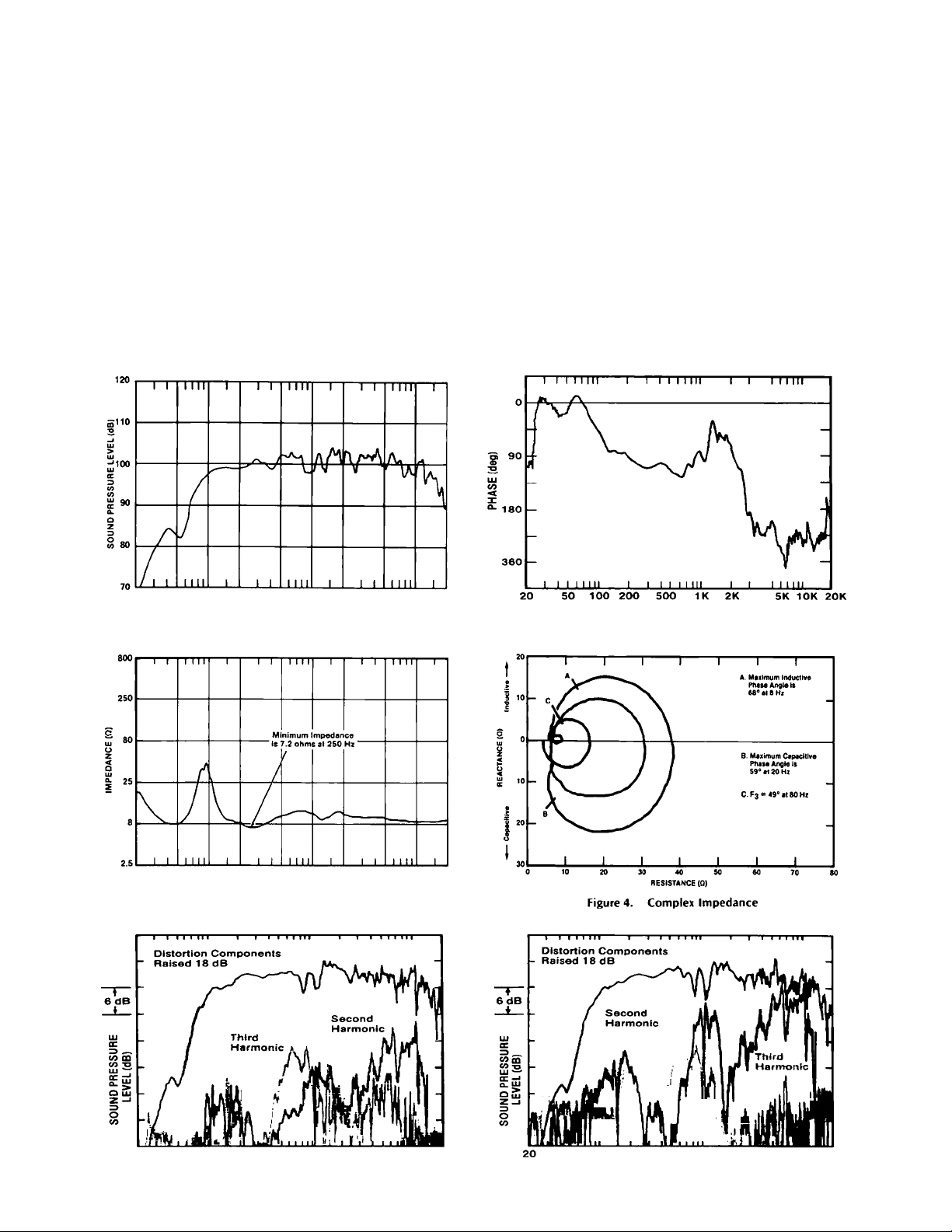
7.20 minimum, maximum inductive phase
angle = 68° at 8 Hz, maximum capacitive
phase angle = 59° at 20 Hz (see Figures
3 and 4, Note 11)
60° horizontally by 40° vertically (see
Figure 8)
16" coaxial loudspeaker, part number
50-03-026768
938-8AO part number 56-06-027683,
938-8AE part number 56-06-027506
Crossover frequency 2 kHz with choice of
Enclosure:
Input Connector:
Replacement H,F,
Diaphragm:
L,F, Recone Kit:
Replacement Grille:
Dimensions:
Net Weight:
Shipping Weight:
Finish:
high frequency attentuation.
Vented type for optimum response, built
of Vi inch (1.9 cm) birch plywood lined
with glass wool, includes tee nut mounting
points on each side and a removable grille.
938-8AD; red and black five way binding
posts and two W phone jacks wired in
parallel.
938-8AE; red and black five way binding
posts and XLR connectors wired in parallel
(Pin 2 is positive and Pin 3 is negative).
Model 26420
R604-8L
Model RC 938
20.5" (52.1 cm) high
22" (55.8 cm) wide
21.5" (54.6 cm) deep
58 lbs. (26.4 kg)
60 lbs. (27.3 kg)
Black, texture finish, polyurethane paint,
black grille cloth
so 100 zoo 500 IK ZK
FREQUENCY (Hj)
Figure 1. Frequency Response (See Notes 1 and 3)
50 100 ZOO SOO IK ZK 5K 10K ZOK
FREQUENCY (Hi)
Figure 3. Magnitude of Impedance
SK I OK ZOK
FREQUENCY (Hz)
Figure 2. Phase Response (See Note 6)
20 SO 100 200 500 IK 2K
FREQUENCY (Hz)
Figure 5. Harmonic Distortion at .01 Rated Power
(1.5 watts, See Note 7)
SK 10K 20K
SO 100 200 500 IK 2K
Figure 6. Harmonic Distortion at 0.1 Rated Power
FREQUENCY (Hz)
(15 watts. See Note 7)
10K 20K
Page 3

Figure 7. One-third Octave Polar
Response Charts
(See Note 8)
HORIZONTAL
VERTICAL
Page 4

Figure 8. Coverage Angle
Figure 10. Florizontal Off-Axis Response Contours
DISTANCE (m]
9000
NOTES ON MEASUREMENT CONDITIONS
1. Figure 1 measurement was taken with network attenuation set in
2. Pink noise signai, one watt caicuiated using EVZmin. 3.16 meter
3. On-axis, one watt caicuiated using EVZmin, 3.16 meter. Measure
4. This system rating patterned after the AES method for individuai
5. This measurement made under the same conditions as Pressure
9600 10200
Figure 12. Energy Time Curve (See Note 9)
the "Fiat" position.
measurement distance referred to one meter.
ment distance referred to one meter, iow frequencies corrected
for anechoic chamber error.
drivers, where the test signai is pink noise with 6 dB crest factor
over the bandwidth of the system, with power caicuiated using
EVZmin, for two hours.
Sensitivity, but at rated power, and takes into account any power
compression effects due to non-iinearities in the system.
10800 11400 12000
TIME (ps)
6. Phase response of the system measured at a time corresponding
to the energy arrival of the high frequency component, as noted
on Figure 12.
7. Distortion components invalid above 10 kHz The percentage
distortion at any given frequency may be found by graphically
Figure 11. Vertical Off-Axis Response Contours
5K 10K 15K 20K
FREQUENCY (Hz)
Figure 13. Time Energy Frequency Curve (See Note 10)
taking the difference between the fundamental and harmonic,
adding 18 dB, and applying the formula: percentage distortion =
lOOx 10.-<<l* chanfiC/20
8. The axis of rotation for all polar plots is the apparent apex of the
high frequency horn. Plots below 200 Hz have not been shown
because of their lack of pertinent information.
9. The time window has been chosen to resolve the arrival times of
low and high frequency components. Frequency bandwidth of
measurement, 800 Hz-2.8 kHz
10. Response decay of the system. Time window is the same as used
in Figure 12, Energy Time Curye.
11. The loudspeaker system should be connected to the eight ohm
tap of amplifiers using transformer coupled output sections.
12. Continuous program is defined as 3 dB greater than the AES
rating using a pink noise signal with 6 dB crest factor.
13. Peak power is defined as 6 dB greater than the AES rating using
a pink noise signal with 6 dB crest factor.
Page 5

Figure 14. Mounting Data
MOUNTING INFORMATION FOR FIXED INSTALLATION
The loudspeaker system is supplied with Vi-20
threaded inserts which allow suspension mount
ing in either 50° or 30° angles (referenced to
a ceiling-plane mounting surface). The user must
supply eyebolts, hexnuts, washers, "S" hooks,
and cables or chains.
Page 6

Figure 15. System Dimensions
ARCHITECT'S AND ENGINEER'S SPECIFICATIONS
The loudspeaker shall be of the two-way multi
purpose type, consisting of a 16" coaxial type
loudspeaker and a dividing network having a
crossover frequency of 2 kHz with variable highfrequency attenuation. The loudspeaker system
shall meet the following performance criteria.
Power rating, 150 w (average) of continuous pink
noise, band-limited from 80 Hz-15 kHz.Frequency
response, smooth and uniformly usable at high
levels from 80 Hz-15 kHz. Pressure sensitivity,
lOOdB SPL at one watt, 80 Hz-15 kHz, measured
from one meter on axis. Impedance, 7.2 ohms,
minimum. The enclosure shall be of the ported
bass reflex type constructed of Ya' ' (1.9 cm) birch
plywood damped with sound absorbent glass
wool. The finish shall be black spatter-finish
polyurethane paint. The dimensions shall be
201/2
" (52.1 cm) high by 22" (55.8 cm) wide by
211/2" (54.6 cm) deep. The loudspeaker shall
weigh 58 lbs. (26.4 kg). The loudspeaker system
shall be the Altec Lansing Model 938-8AD or
Model 938-8AE.
PRINTED IN U.S.A. 5/89-3M
AISTEIC
LANSIISIG
P.O. BOX 26105, OKLAHOMA CITY, OKLAHOMA 73126-0105, U.S.A.
A1989 ALTEC LANSING CORPORATION
AL-2565
42T)7-027608
 Loading...