

Page 1
909-8B/16B
P ROFESSIONAl
1” Exit High Frequency
Compression Driver
21216B
1” Throat To 1.4” Throat
Adaptor
MR II 564B
Medium Throw 60º x 40º
MantarayTM1.4” Throat
High Frequency Horn
FEATURES - THE ALTEC LANSING DIFFERENCE
• Superior Bandwidth
• High Performance 30W AES / 120W Peak Power Handling
• Smooth and Transparent
909-8B/16B GENERAL PRODUCT DESCRIPTION
Altec Lansing’s 909-8B and 909-16B small format, high frequency,
compression drivers are designed for use in professional sound
reinforcement systems where both wide bandwidth and high acoustic
output level are essential. When used with Altec Lansing MantarayTMhigh
frequency horns, the energy produced by these drivers can be directed to
cover an audience accurately to the highest threshold of human hearing.
Their wide range response, when complemented by Altec Lansing low
frequency loudspeaker systems, will provide smooth reproduction of
speech and music for installations in auditoriums, churches, stadiums, and
arenas.
The robust Pascalite diaphragm extends the driver’s power handling
capability, while maintaining superior high frequency bandwidth. The
compact magnetic motor-structure, utilizing a 2.5 lbs. (1.1 kg) ferrite
magnet, provides a 1.8 T gap flux density. An exclusive TangerineTMradial
phasing-plug assures a smooth upper range response.
The excellent performance characteristics of these drivers make them the
high frequency component of choice for small to medium size sound
systems when premium dynamic reproduction is required.
MR II 564B GENERAL PRODUCT DESCRIPTION
Altec Lansing's MR II 564B Mantaray
efficient mid and high frequency response with proper loading down to
500 Hz, plus excellent directivity control over its 60°H x 40°V coverage
pattern.
The geometry of the MR II 564B reduces the problem of high frequency
beaming and maintains uniform dispersion at all frequencies within the
rated frequency range. Therefore, the same quality sound will be heard
by listeners sitting off-axis and on-axis to the MANTARAY
Altec Lansing’s 21216B adapter is constructed of heavy gauge aluminum.
This adapter is the perfect choice for coupling the 909-8B and 909-16B to
our MANTARAY
TM
series horns.
TM
constant-directivity horn features
TM
horn.
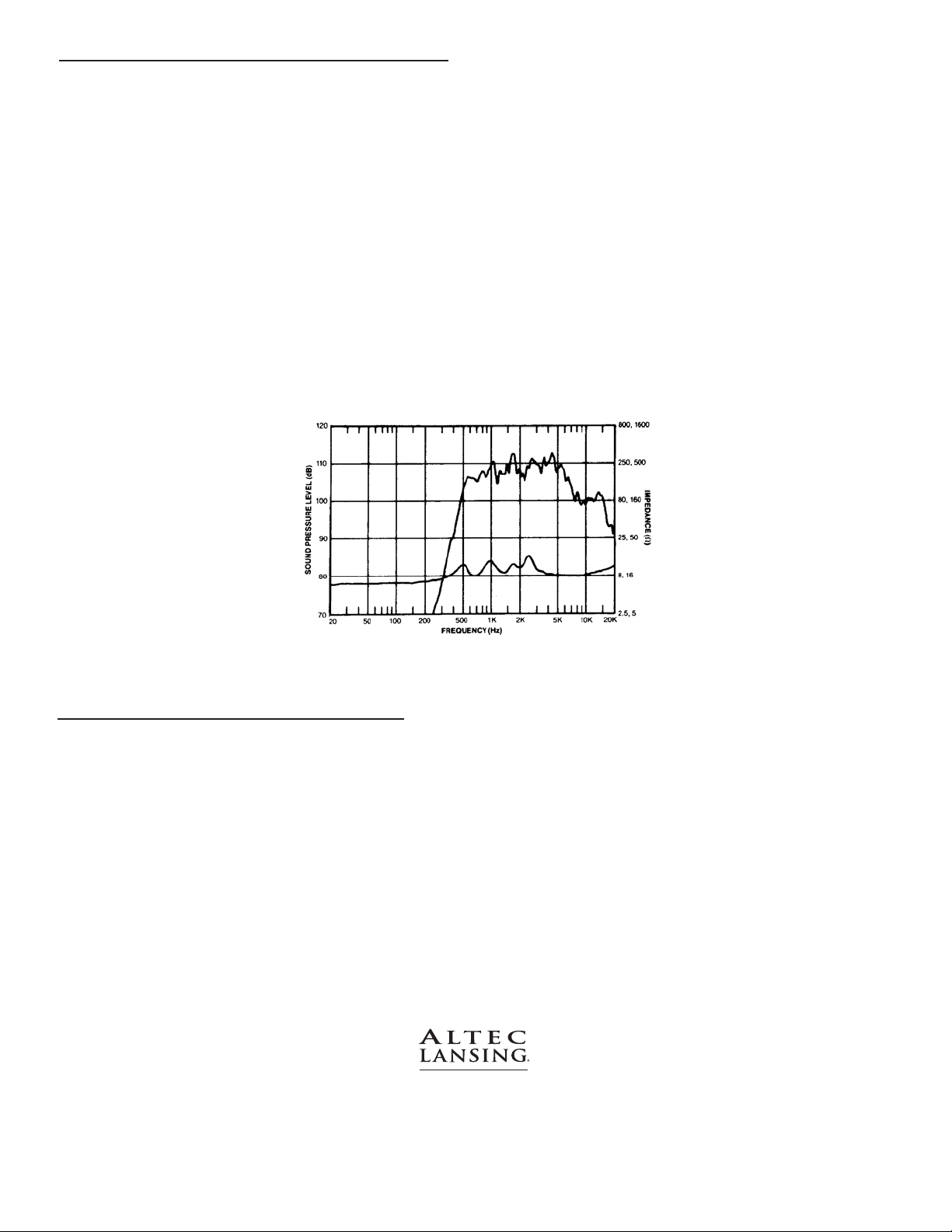
FREQUENCY RESPONSE
1, 2
909-8B with MR II 564B: 500 Hz – 20 kHz
(flat 500 Hz – 6 kHz)
USABLE LOW FREQUENCY LIMIT
1, 2
500 Hz
USABLE HIGH FREQUENCY LIMIT
1, 2
20 kHz
SENSITIVITY
3
909-8B with MR II 564B: 110 dB SPL
POWER HANDLING
4
> 500 Hz: 30 W continuous; 120 W peak
> 1 kHz: 60 W continuous; 240 W peak
MAXIMUM OUTPUT (1 m)
5
909-8B with MR II 564B: 130 dB SPL
COVERAGE ANGLES
6
MR II 564B: 60º (horizontal) by 40º (vertical)
DIRECTIVITY FACTOR, Q
6
MR II 564B: 23.0
DIRECTIVITY INDEX, DI
6
MR II 564B: 13.6 dB
IMPEDANCE
7
Nominal: 8.0 Ohms or 16.0 Ohms
Minimum: 8.0 Ohms or 16.0 Ohms at 6 kHz
HARMONIC DISTORTION
8
THD: 1.59%
INPUT CONNECTIONS
1 x 2 position barrier strip with 0.250 in.
blade type terminals
FINISH
Dark gray enamel
REPLACEMENT HF DIAPHRAGM ASSEMBLY
26420: 8 Ohms
26421: 16 Ohms
MOUNTING DATA (DRIVERS)
Two 3/8-24 studs on a 3.0 in. diameter bolt circle
(Altec Lansing Standard)
DIMENSIONS
909-8B/16B Diameter: 5.5 in. (140 mm)
Depth: 2.7 in. (69 mm)
MR II 564B Height: 12.75 in. (324 mm)
Width: 12.75 in. (324 mm)
Depth: 12.50 in. (318 mm)
21216B Height: 3.25 in. (83 mm)
Maximum Diameter: 5.5 in. (140 mm)
NET WEIGHT
909-8B/16B: 6.4 lbs. (2.9 kg)
MR II 564B: 5 lbs. (2.3 kg)
21216B: 1 lbs. (0.5 kg)
SHIPPING WEIGHT
909-8B/16B: 7.2 lbs. (3.3 kg)
MR II 564B: 7 lbs. (3.2 kg)
21216B: 1.6 lbs. (0.7 kg)
1000 W. Wilshire Blvd., Suite 362 • Oklahoma City, Oklahoma 73116 • Phone: 1-405-848-3108 • Fax: 1-405-848-3217 • www.altecpro.com
Page 2
ARCHITECT’S AND ENGINEER’S SPECIFICATIONS
The motors shall be a small format high frequency compression
driver. These drivers shall have an operating bandwidth of 500 Hz
to 20 kHz. The power handling capability of these drivers shall be
be 30W AES (120 W peak) > 500 Hz and 60W AES (240W peak)
> 1 kHz. One driver shall have a minimum impedance of 8 ohms (at
6 kHz), and the other driver shall have a minimum impedance of
16 ohms (at 6 kHz).The voice-coil for these drivers shall be an edge-
wound, aluminum ribbon, which is 1.75 inches (44 mm) in
diameter. The drivers shall have a diaphragm that features an allmetal, Pascalite dome and tangential compliance. The magnetic
gap of the drivers shall have a flux density of 1.8 T, resulting from
a 2.5 lbs. (1.1 kg) ferrite magnet. A TangerineTMphasing-plug with
eleven radial acoustic slots shall provide the proper phase
relationship between sound emanating from the center and edges
of the diaphragm’s dome on these drivers. The entire diaphragm
and voice-coil assembly for these drivers shall be field replaceable
without requiring special tools. The drivers shall be 5.5 inches (140
mm) in diameter by 2.7 inches (69 mm) deep, excluding the one
inch (25.4 mm) depth of the mounting studs. The drivers shall
FREQUENCY RESPONSE AND IMPEDANCE MAGNITUDE OF 909-8B ON MR II 564B
weigh 6.4 pounds (2.9 kg).The high frequency compression drivers
shall be the Altec Lansing model 909-8B and the Altec Lansing
model 909-16B.
The projector shall be a constant-directivity mid and high
frequency horn. The horn shall have an operating bandwidth of
500 Hz – 20 kHz. The horn shall have a mean horizontal dispersion
angle of 60° and a mean vertical dispersion angle of 40°.When the
909-B series drivers are coupled to the 60° x 40° horn, this
combination shall have a sensitivity of at least 110 dB, when
measured on-axis, at a distance of one meter, with a one Watt
input. The constant-directivity mid and high frequency horn shall
be the Altec Lansing model MR II 564B.
The adaptor shall be designed to couple Altec Lansing’s small
format drivers to large format 1.4” horns. The adapter shall be
constructed of heavy gauge aluminum. The adaptor shall have a
maximum diameter of 5.5 in. (140 mm) and a height of 3.25 in.
(83 mm). The adaptor shall weigh 1 lbs. (0.5 kg). This adapter shall
be Altec Lansing’s model 21216B.
As we are continually striving to improve Altec Lansing products, specifications are subject to change without notice.
Please visit www.altecpro.com for the latest information on Altec Lansing Professional products.
SPECIFICATION NOTES
1 The frequency response of the loudspeaker is measured at a distance of no less than 3 meters to obtain full range data. The level is then corrected to be
equivalent to a 2.83 V 1 m measurement.
2 The limits of the frequency response are referenced to -10 dB of the loudspeaker’s rated sensitivity.
3 The sensitivity of the loudspeaker is the log based average SPL taken over the intended bandwidth of operation for the loudspeaker with a 2.83 V swept sine
stimulus. The data is measured and level corrected in a manner consistent with note 1.
4 The power handling capacity of the loudspeaker is tested using a full range form of AES Standard 2-1984. The test stimulus is band limited (500 Hz – 16 kHz) pink
noise with a 6 dB crest factor. The applied RMS voltage is determined using the minimum impedance of the loudspeaker. The amplifier used to drive the
loudspeaker has a minimum operating headroom of 6 dB referenced to the RMS voltage.
5 The peak output level of the loudspeaker is calculated based on the sensitivity and the peak power handling capabilities of the loudspeaker.
6 The coverage angles for the loudspeaker are taken as the -6 dB points of the directivity response and averaged from 500 Hz – 16 kHz.
7 The minimum impedance of the loudspeaker is taken over its intended band of operation.
8 The distortion measurements of the loudspeaker are performed at a distance of 1 m with RMS input voltages corresponding to 10% of rated power handling
calculated using minimum loudspeaker impedance. The distortion percentages are log based averages from 500 Hz – 10 kHz.
VISIT WWW.ALTECPRO.COM FOR
• Authorized EASE data on all Altec Lansing Professional loudspeakers
• Specification sheets in .pdf format. Download page 1 of the specification sheet for you submittals.
• One paragraph A&E Specifications in .doc format
P ROFESSIONAl
© 2003 Altec Lansing Professional
1000 W. Wilshire Blvd., Suite 362
Oklahoma City, Oklahoma 73116
Phone: 1-405-848-3108 • Fax: 1-405-848-3217
Web: www.altecpro.com • Email: proinfo@alteclansing.com
AW1080 REV02
 Loading...