

Page 1

LArslSING
sound
of
3300A
Mixing Consoles
Operating Instructions
ALTEC LANSING CORPORATION
a MAKK IV company
P.O. Box 26105 • Oklahoma City, OK • 73126-0105 USA « Tel: (405) 324-5311 • FAX: (405) 324-5981
Page 2

Operating Instructions for the Altec Ixmsing 3300A Series Mixing Consoles
TABLE OF CONTENTS
1 ELECTRICAL.............................................................................................................................................................. 3
1.1 120 Vac, 50/60 Hz Power Connections.................................................................................................................
1.2 100, 220, 240 Vac, 50/60 Hz Power Connections ................................................................................................. 3
2 INSTALLATION.......................................................................................................................................................... 3
2.1 Rack Mounting................................................................................................................................................... . 3
2.2 Ventilation.................................................................................................................................................... . - 3
3 SIGNAL CONNECTIONS.......................................................................................................................................... 3
3.1 Input Connections ..............................................................................................................................................- 3
3.2 Output Connections .............................................................................................................................................. 4
3.3 Insert Connections............................................................................................................................................... 4
4 OPERATION................................................................................................................................................................ 4
4.1 Input Channel Controls
4.2 Output Section Controls........................................................................................................................................ 3
4.3 Rear Panel Input Connectors .................................................................................................................... * - ■ • 7
4.4 Rear Panel Output Connectors.............................................................................................................................. 9
4.5 Rear Panel Switches............................................................................................................................................ 10
......................................................................
-................................................................ 4
S
5 MOVEABLE REAR PANEL ON THE 3308A MIXER .......................................................................................... 11
6 WRITE-ON LABELS..................
7 SYSTEM SPECIFICATIONS
. 11
. 12
8 SERVICE INFORMATION........................................................................................................................................... 16
8.1 Ordering Replacement Parts............................................................................................................................... 16
8.2 Factory Service .................................................................................................................................................. 16
8.3 Technical Assistance........................................................................................................................................... 16
8.4 Schematics.......................................................................................................................................................... 16
8.5 Component Parts Listing .................................................................................................................................... 24
TABLE OF ILLUSTRATIONS
Figure 1. Typical input connections ........................................................................................................................... . , , . 3
Figure 2. Typical output connections .................................................................................................................................. 3
Figure 3. Typical insert connections
.................................................................................................................................. 4
Figure 4, Input channel controls........................................................................................................................................... 4
Figure 5. Output section controls ................................................................................................................................... - 6
Figure 6. Rear panel input connectors ..............................................................................................................................
8
Figure 7. Rear panel output connectors................................................................................................................................ 9
Figure 8, Rear panel switches.......................................................................................................................................... , lO
Figure 9. 8308A moveable rear panel................................................................................................................................ 11
Signal Flow Diagram......................................................................................................................................................... 13
Transformer Primary Wiring Diagram............................................................................................................................. 16
Mixing Console Wiring Diagram.................................................................................................................................. • 17
Input Board Schematic....................................................................................................................................................... 18
Sub Board Schematic......................................................................................................................................................... 19
Main Board Schematic....................................................................................................................................................... 20
Monitor Board Schematic.................................................................................................................................................. 21
Relay Board Schematic...................................................................................................................................................... 22
Power Supply Board Schematic......................................................................................................................................- 22
Display Board Schematic .................................................................................................................................................. 23
ALTEC LANSING^ CORPORATION * a Mark IV Company
Page 3
Operating Instructions for the Altec Lansing 3300A Series Mixing Consoles
1 ELECTRICAL
1.1 115 Vac 50/60 Hz Operation
Tlie mixing console is provided with
the voltage select switch in the 115
Vac position. Its power supply design
allows it to be powered from 100 Vac
to 120 Vac lines in this switch posi
tion.
1.2 230 Vac 50/60 Hz Operation
The mixing console may be powered
by line volta^s from 220 Vac to 240
Vac by switching the voltage select
switch to tlie 230 Vac position. How
ever, the ac line fuse must be
changed. Refer to Table I for proper
fiise value.
WARNING: Veri^ that the voltage
select switch is in the desired
position, and the proper fuse is in
place for the intended ac line voltage
BEFORE applying power to the
mixing console.
2 INSTALLATION
2.1 Rack Mounting
The 3308A mixer may be placed in a
standard 19 inch equipment rack. It
requires 17,5 inches of vertical speice
(10 standard EIA vertical rack
spaces). For more information on
rack-mount installation, refer to
Section 5 and Figitre 9 of this
manual.
2.2 Ventilation
The 3300A series mixii^ consoles
should not be used in areas where
the ambient temperature exceeds
eO^C (140°F).
Table I. Fuse Selection Chart
I
iOO niA/250 V
300 mA)2M> V
230 niA)250 V
AC LINE
FUSE
AC LINE
VOLTAGE
100 V— 120 V
(8 anii 16 ch only)
100 V — 120 V
eh only)
220 V — 2<I0 V
3 SIGNAL CONN liCTIONS
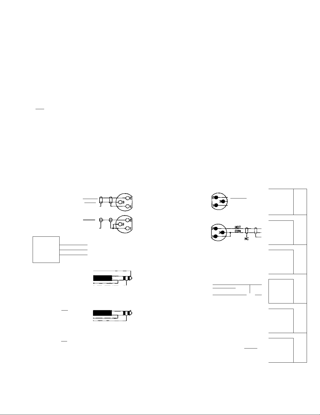
3.1 Input Connections
Balanced microphc -ne inputs may hi
made to the 3-pin XLR-^jqje con
nector. Balanced line inputs may hi
made to the Vi-inch phone (TRS
connector. For single-ended inputs
strap the low (—) input (pin 3 oi
XLR or Ring on %-inch phone) h
ground. Otherwise;, the electronically
balanced input stage will see 5 dl
less input signal level than with i
balanced input. Refer to Figure 1 fo:
typical input connect ions.
BALANCED
LO-Z
MIC
UNBALANCED
LO-Z
MIC
BAUINCED
LINE
LEVEL
SOURCE
UNeALANCED
LINE
LEVEL
SOURCE
m
UNBALANCED
LINE
LEVEL
SOURCE
UNBALANCED
LINE
LEVEL
SOURCE
M 1*1
J LA
HOT
HI 1+1 p
1
LC H
Y V 1
NC
jjCEL
Not recoABendfid foi* rtm? over 6 feet.
HOT
Not rocoauendeit for runs over B feet.
HPT
-e-r&
J
NC
p---------------—
J
----------------------------
-----------------
^ HI-Z
—UNBALANCED
r^LINE
J INPUT
LO-Z
MIC
INPUT
LO-Z
MIC
INPUT
HI-Z
BALANCED
LINE
INPUT
HI-Z
BALANCED
LINE
INPUT
1 HI-Z
BALANCED
LINE
INPUT
NC
1
1 balanced
Í load
:;);B ALANCEO
__
:.::3AUNCED
__
BALANCED
—1 LOAD
BALANCED
—^ LOAD
UNBALANCED
___
SERVOBALANCED
OUTPUT
SERVOBALANCED
OUTPUT
Mot reconaentfea for runs over 6 feet.
HL-Vl-
^RVO-
BALANCED
OUTPUT
Not recommeniied for runs over ipo feet. BALANCED
UNBALANCED
OUTPUT
Not reconnenoed for runs dver 6 feet.
UN8AU1NCED r
OUTPUT ^
Not recoradended (or runs over 5 feet
UNBALANreO 1
1
--------
____________-
-------
— —
3"
CGH
OUTPUT <dll|^H!i
“i
LOAD
LOAD
^ LOAD
-
Figure 1. Typical input connections.
ALTEC LAVS/VG* CORBORATJOti • a Mark IV Company
Figure 2- Typical output connections.
Page 4
Operating Instructions for the Altec Lansing 3300A Series Mixing Consoles
3.2 Output Connections
The main outputs of the mixing con
sole are electronically servohalanced. Bzilanced output connec
tions may be made to the male 3-pin
XLR-type connectors. For singleended outputs, strap the low (—)
output (pin 3 on XLR or Ring on ‘/cl
inch phone) to ground. Otherwise,
the electronically servo-balanced
output stage will produce 6 dB less
output signal level than with a
balanced output connection.
Unbalanced connections may be
made to the other Vi-inch phone
(TRS) connectors. Refer to Figure 2
for typical output connections.
3.3 Insert Connections
Signal processing equipment may
easily be inserted in the signal path
by using the Vi-inch phone (TRS) in
sert connectors. The external device
must have line level unbalanced in
puts and outputs. The output signal
from the mixing console is on the
Tip and the input signal is on the
Ring. Tlie Sleeve is ground. Refer to
Figure 3 for a typical insert
connection.
4 OPERATION
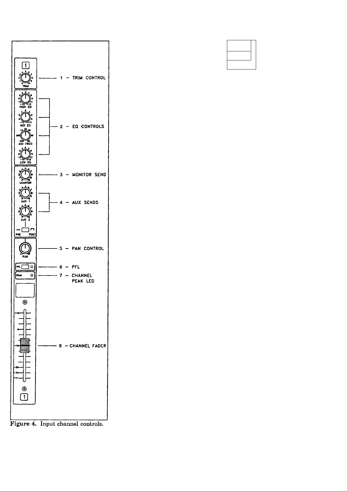
4.1 Input Channel Controls
(Refer to Figure 4.)
The input channel is the beginning
of the signal amplification chain of
the mixer. Each input channel will
accept one signal source which may
be equalized, have effects added and
sent to the monitor and main ^stem
for the audience to hear. Each input
hcis a low-impedance microphone in
put (the 8-pin XLR connector) and a
high-impedance microphone or line
input (V«-inch phone jack). The line
input will accept signals from an
instrument, high-impedance micro
phone, tape/CD player, keyboard or
electronic drums or eilmost any other
audio source. Always make sure that
the channel fader (see Figure 4)
I IMUU.ANCCO
j 1 IWVT
1 wjtS/t
EXTEBNiL
EFFECTS
PROCESSOR
^
____
pL.
CHANNEL
“X
h
Y
Aid SUB
•^IS
Figure 3. Typical insert coimection.
and/or master faders (see Figure 5)
are down before plugging or unplug
ging input sources.
1. TRIM Control: This control
adjusts the gain of the input
amplifier to accommoriaie the
wide variation in signal
strength presented to the mixer
by the endless variety of signal
sources.
1110 TRIM control
allows the amplification of each
individual input source to be
optimized. Correct setting of the
TRIM control results in the best
signal-to-noise ratio (no iiiss),
the greatest dynamic range, and
the freedom from overload dis
tortion.
To set the TRIM control
correctly, first set the channel
fader at minimum and depress
the channel PFL switch. Make
sure the source (mic,
instrument) that is plugged into
the channel is used at its
nominal performance level.
Increase the TRIM level until
the level of the PFL meter
reaches 0 VU. Gradually bring
the channel fader up to Uie
desired listening level, 'iliis
insures that nominal level is
maintained throughout the
input channel.
If the level is too low in :e
trim’s gain circuit, hiss . ill
occur. If the level is too high in
the TRIM circuit, overloac' istortion will occur. Keeping ‘-e
channel faders at nominal 1( el
with proper setting of the TT ; ' T
control will keep the sy^’- n
sounding its best and Is
quietest.
ALTEC LANSING^ CORPORATION • a Mark IV Company
Page 5

Operating Instructions for the Altec Lansing 3300A Series Mixing Consoles
2. EQ Controls: Equalization can
be more simply described as so
phisticated tone control. The
EQ circuits used in the 3300A
series have a substantial
amount of sound shaping
capability.
This wide range ceui be a bonus
when dealing with widelyvarying instrument signals, poor
acoustics or other problems. The
EQ should be used sparingly,
however, for the best results.
Too liberal use of the EQ can
cause phasing problems, add
noise, and use up a lot of ampli
fier power.
2A- HIGH EQ: The high EQ
circuit is a shelving type
filter at 10 kHz with a ±15
dB rzuige. It controls the
treble content of the input
signal Turning the control
counterclockwise decreases
the amount of treble,
clockwise increases it.
2B. MID EQ: The mid EQ cir
cuit is a peaking type filter
with a ±15 dB range. It
controls the midrange con
tent of the input signal.
Turning the control coun
terclockwise decreases the
amount of midrange, clock
wise increases it.
2C. MID Frequency: The mid
frequency circuit controls
the frequency range from
300 Hz to 5 kHz of the
MID EQ control. By vary
ing the FREQUENCY, dif
ferent tonal perspectives
can be created. The sweepable frequency gives much
more control flexibility.
2D. LOWEQ: The low EQ cir
cuit is a shelving type filter
at 100 Hz with a ±15 dB
range. It controls the bass
content of the input signal.
Turning the control coun
terclockwise decreases the
amount of bass, clockwise
increases it.
8. MONITOR Send: The monitor
send control sets the level of
that input signal in the monitor
mix. It is independent of all
input channel controls except
the TRIM control. It is not
affected by the channel EQ
controls or slide fader. Thus, it
is independent of, zmd not
affected by, changes in the main
or house mix.
4. AJJX Sends: Ilie AUX 1 send
control sets the level of that
signal in the AUX 1 mix and is
{x>st-fader, which means that it
is affected by the gain setting of
the fader. The AUX 1 send may
also be used as a mono send for
recording.
The AUX 2 send control sets the
level of that input signal in the
AUX 2 mix and is switchable
PRE or POST fader. In the PRE
position, it serves as another
MONITOR OUT, and in the
POST position, another
EFFECTS OUT.
5. PAN Control: Short for "pan
oramic potentiometer", this con
trol allows the channel’s input
signal to be placed within the
stereo image by assigning more
or less of the signal to the left or
right subgroup controls. Turn
ing the panpot to the left of
center moves the apparent
source toward the left channel.
Turning the panpot to the right
of center moves the apparent
source towzird the right channel.
Centering the control makes the
apparent source centered be
tween the channels. If all inputs
are panned center, the result is
mono.
Some users p>an all the instru
ments to one side and the vocals
to the other and use the sub
group controls to valance them.
6. PFL: PFL(pre-fader listen)
allows the open : to preview
any pre-fader sij, individually
or in combinaLi- through the
headphone out . To activate
the PFL simply ' >press the ap
propriate switcl: The status
indicator will . iit indicating
which pre-fader signals are be
ing monitored. hen the PFL
circuit is engag ' by depressing
a PFL switch, ^ th the right
meter and the headphone circuit
will monitor the audio level of
the selected cha;:ael(s).
In the normal position (all PFL
switches off), tile right meter
monitors the METER switched
bus, and the headphone circuit
monitors the out put of the SUB
L and SUB outputs. The
audio level of ,.he headphone
jack is controlled by the
PHONES conlrri.
7. Channel PEA^ LED: The
channel PEAK IjED monitors
the input channel circuit for
clipping or overload (both before
and after the EQ section). If it
lights, the sign;:, is bordering on
distortion. 'Ihis will be heard in
the output as aarsh, blaring
sound on voiame peaks. This
might be caused by excessive
boost in he channel
equalization controls, or a TRIM
control setting that is too high
for the input signal Generally,
readjusting the TRIM control
will cure '.is undesired
condition.
8. Channel Fader: The slide
fader controls the output level of
the channel as it is fed to the
subgroups. Tl.;: control should
be normally set around the "0"
mark (nomiiia. level). At this
point, the signal level is high
enough to K.eep noise from
creeping in and low enough to
insure plenty of headroom and
ALTEC LANSING* CORPORATION • a Mark IV Company
Page 6

Operating Instructions for the Altec Lansing 3300A Series Mixing Consoles
4.2 Output Section Controls
1. TO MON Send (AVX 1. AUK
freedom from clipping
distortion. If the fader must run
wide open to get enough, level,
turn up the TRIM control
judiciously or increzise the level
setting of the left and right
subgroup controls. Conversely,
if the fader must be pulled way
back to get the right level, the
TRIM control or ;ereo
subgroup should be adjusted.
Adjust the TRIM control ii’ the
PEAK LED lights, otherwise ad
just the stereo subgroups. For
optimum performance, the
channel FADERS should be run
close to the "0" mark.
(Refer to Figure 5.)
2): The TO MON level control
determines the amount of exter
nally generated effects signals
in the monitor mix. With the
use of this control, the
performers can hear the added
effects in their monitors.
Figure 5. Output section controls.
2. Effects SEND (AUX1,AUX2):
The effects SEND control sets
the level of the signal appearing
at the effects send output
jack(s) going to any type of
outboard effects device(s) such
as a digital reverb. Hanger,
compressor/limiter, etc. The
source of this signal is via the
individual AUX 1 and AUX 2
send level controls on each
input channel.
3. Effects RETURN (AUX 1,
AUX2): The effects RETURN
level control determines the
amount of externally generated
effects signals in the main mix.
This signal is mixed into the
left and right stereo sub
channels via the AUX 1 and
AUX 2 PAN control(s).
4. PAN Control (AUX 1, AUX
2): The effects PAN control
(AUX 1, AUX 2) directs the
signal coming from the effects
ALTEC LANSIN(f CORPORATION • a Mark IV Company
Page 7

Operating Instructions for the Altec Lansing 3300A Series Mixing Consoles
RETURN level control(s) into
the left Eind/or right sub
chaumels. The control works in
an identical way to the input
channel PAN control.
5. Master Section Controls:
The master section controls
affect the subgroup, main, and
monitor output levels.
The use of subgroups can be
shown by this example: If the
input channel PAN controls are
set fully clockwise for all the vo
cals, then the SUB R fader has
been assigned as a "vocal sub
master”. If the SUB R fader is
raised or lowered, the vocal
level in the mix can be set while
preserving the input channel
balance set among the vocalists.
5A. SUB L (Left Submaster):
Controls the volume of the
left stereo output channel.
It is also used as a
subgroup master.
SB. SU B R (Right
Suomaster): Controls the
vol .ne of the right stereo
01 'ut channel. It is also
1 d as a subgroup master.
5C. MAIN Master: The MAIN
(monaured) output is the
summed mix of the left and
right stereo outputs. The
MAIN master controls the
volume of the output.
5D. MON (Monitor Master):
Controls the volume of the
monitor output signal. The
monitor output is a mix of
the individual channel
monitor sends.
6. TAPE L and TAPE R: These
controls adjust the level of the
tape left and tape right returns.
7. PHONES (Headphone Level):
The PHONES gain control sets
the level at the headphone jack
(front panel on the 3324A and
the 3316A; top panel on the
3308A). Any signal selected by
depressing a PEL switch will be
monitored through the head
phone jack. Without any of the
PFL switches depressed, the
headphone circuit monitors the
left and right subgroup outputs
in stereo.
8. METER Assignment Switch:
A push-push switch is provided
to allow the user to select the
points in the circuit which are
monitored by the VU meters.
When the switch is depressed,
the indication will be the audio
level at the MAIN and MONitor
outputs. In the other (nondepressed) position, signal level
at the SUB Left and SUB Right
outputs win be shown.
9. VU Meters: Two "B" scale ana
log VU meters with integral
peak lights are used to indicate
signal level at selected points in
the circuit (see meter assign
ment switch and PFL switches).
The meter scede indicates a
range from —20 dB to +4 dB
with 0 VU = -1-4 dBu, a stand
ard in the industry. The
integral f>eak light, located in
the upper right-hand corner of
each meter, shows when the
output is above the -1-14 dB
level and the headroom is being
rapidly exhausted and distortion
is imminent. The meters read
either lefl/right stereo, or
main/monitor level. If any of the
PFL switches are depressed, the
right meter will monitor the
PFL bus signal. A PFL LED is
provided on the meter bridge to
acknowledge the condition.
10. LAMP Connector; A BNC-type
socket is provided at the top of
the mixer panel to accommodate
a Littelite* gooseneck lamp to
allow operation of the board in
low-light conditions. These
lamps are available in different
lengths from many professional
sound dealers and attaches
without tools. 'Hie LAMP
connector car. accommodate
either normal or 'gh intensity
lamps.
11. POWER Switch: The power
switch is used to turn the main
ac power on and off.
12. POWER Indicator: This LED
(green) is ilium Ij atcd when the
main ac power is m.
13. PHANTOM Power Indicator:
This LED (red' indicates when
phantom power present at
the microphone inputs.
14. PFL Indicator: This LED
(amber) indicates when the PFL
circuit is activated and shows
that the right meter is reading
the PFL bus sigiial level.
4.3 Rear Panel Input
Connectors
(Refer to Figure 6.)
The 3300A series :.:i;ier can accept
program material covering a dynamic
range of over 100 dB. All of the line
inputs cam safely accept signal levels
up to -f20 dBu. (See specifications
for details.) All lim- inputs are made
through standeiru '/i-inch phone jacks
(except for TAPE inputs). Several of
the inputs that directly access the
mix buses can L.. .ised to stack
mixers together without using up an
input channel. The stacking group
includes the AUX , AUX 2, euid
MONITOR inputs. The AUX return
inputs may also be used as stacking
inputs. For stereo subgroup stacking,
set the AUX 1 PAN control to L, and
the AUX 2 PAN control to R and use
AUX 1 and 2 RETURNS for lefi and
right stacking, respectively.
1. Balanced Low-Z Mic Input:
A female a-pin XLR-type
connector is used for balanced
low-impedam-e microphones.
The MIC .. 'PUT is actively
ALTEC LANSING* CORPORATION • a Mark IV Company
Page 8

Operating Instructions for the Altec Lansing 3300A Series Mixing Consoles
baleinced; active balancing
allows elimination of the input
transformer (along with its
limitations) while maintaining
the RF auid hum rejection of a
good transformer-coupled input.
It is important during operation
or testing of the mixer that all
faders remain fully down when
ever the mic input is not
perly terminated with a micro
phone or an equivalent 150-ohm
source. An open mic input
invites the introduction of high
noise levels which could produce
lower quality sound or an
incorrect test measurement.
High-Z Line Input; A
standard Vi-inch phone jack is
used for balanced or unbalanced
line level signals. Examples of
these signeds include most
electronic keyboards, drum
machines and synthesizers, tape
pro
decks, CD players, etc. All input
channel controls, including the
variable TRIM control, affect
the LINE input. Maximum
input level before preamp
clipping is -1-24 dBu (12.3
Vrms).
If a sufficient signal level is not
possible with the TRIM control
at its furthest clockwise
position, the input signal must
then be treated as a mic level
signal and connected to the
microphone input. If necessary,
use an appropriate balancing
transformer or a direct box with
the microphone (XLR) input.
AVX RETURN (AUX 1 and
AVX 2): The AUX RETURN
jack(s) feed signals to the
subgroup buses. The signal is
controll^ by the RETURN and
PAN front panel controls.
4. AVX IN (AVX 1 and AVX 2):
The AUX IN jack(s) will put
signals directly into the respec
tive AUX bus. Crosstalk and
buffering protection .re
provided by the input circuit
Eind the signal level is controlled
by the external source.
5. MON IN: The MON IN J^ck
will put signals directly onto the
monitor bus. Crosstalk and
buffering protection are pro
vided by the input circuit and
the signal level is controlled by
the external source.
6. TAPE RETURN: These RCA
jacks Eillow a tape deck or CD
player to be directly connc-cied
to the mixer. The input is fed
into the left and right sub
groups and its level is controlled
by the TAPE L and TAPE R
front panel controls. These jacks
can also be used as other AUX letun s.
ALTEC LANSING* CORPORATION • a Mark IV Company
Page 9

Operating Instructions for the Altec Lansing 3300A Series Mixing Consoles
figure 7. Rear panel output connectors.
7. INSERT L and R (SUB L
and SUB R): A space-saving
3-conductor (stereo) phone jack
is used for both output from
SUB L and SUB R respectively,
emd for the return to the
mixer’s master section from an
external processing device. Be
sure that the device that is to
be patched in heis line level
unbalanced inputs and outputs.
The signal at the insert jack can
drive loads of 2000 ohms or
greater and the external
processing device should have a
low output internal impedance
(100 ohms or less). Refer to
Section 3.3 of this manual and
Figure 3 for proper connections.
A nominal input signal is a level
of -1-4 dBu; the maximum level
is -(-20 dBu.
(stereo) phone jack is used for
both output from the input
channel and for the return to
the input channel from an
external processing device. Be
sure that the device that is to
be patched in has line level
unbalanced inputs and outputs.
The signal at the insert jack can
drive loads of 2000 ohms or
greater and the external pro
cessing device should have a low
output internal impedance (100
ohms or less). Refer to Section
3.3 of this manual and Figure 3
for proper connections.
A nominal input signal is a level
of -f4 dBu; the maximum level
is -1-20 dBu.
4.4 Rear Panel Output Connec
tions (Refer to Figure 7.)
outputs are servo-balanced and made
through chassis-mount male 3-pin
XLR-tyf>e connectors to a meiximum
level of -1-24 dBu (12.3 Vrms).
All other output connections are line
level, unbalanced, and made through
standard V4-inch phone jacks (except
for RECORD OUT).
1. SUB L Output: This left sub
group output is derived by sum
ming all of the points (channels
and externa'.) assigned to the
left subgroup bus. A PAN con
trol rotated fully counterclock
wise to the ’L” position will
assign that signal only to the
left bus.
2. SUB R Output: This output is
the right subgroup equiveJent of
the SUB L output.
8. Input Channel INSERTs: A
space-saving, 3-conductor
ALTEC LANSING^ CORPORATION • a Mark IV Company
In the 3300A series mixers, the SUB
L, SUB R. MAIN, and MONITOR
3. MAIN Output: The MAIN
output is the summed mix of
Page 10

Operating Instructions for the Altec Lansing 3300A Series Mixing Consoles
Figure 8. Rear panel switches.
the left and right subgroup
outputs. Since the 3300A series
are true subgroup mixers, all
signals that appear in the main
mix must come through the
subgroup channels.
4. MONITOR Output: The
MONITOR output signal is the
sum of all the input cheuinel
monitor sends and the external
monitor input signal.
5. AUX SEND (AVX 1 and
AVX2): The AUX SEND out
put signal is the sum of all of
the input channel AUX sends
(PRE or POST fader) plus any
signal coming through the AUX
IN input.
6. TAPE RECORD: These
output signals are the sum of all
the input channels and effects
with their position in the L R
stereo mix. The TAPE RECORD
output is via RCA-jacks fixed at
-10 dBV for easy interfacing and
compatibility with semi-pro and
hi-fi tape decks.
4.5 Rear Panel Switches
(Refer to Figure 8.)
1. PHANTOM POWER Switch:
lliis switch turns the phantom
power supply on and off. The
phantom power supply provides
power for condenser-type micro
phones through the microphone
cable. When switched on, it
provides 48 volts dc at pins 2
and 3 on all of the microphone
input connectors. Pin 1 (the
shield conductor) provides the
ground return path. This will
power standard condenser
microphones. When switched on
or off, the voltage will slowly
ramp up or down; it teikes a few
seconds to reach full level. This
prevents unwanted transients
from reaching the microphone
inputs. When the switch is en
gaged, a red LED will light on
the meter bridge to confirm its
operation.
2. VOLTAGE SELECT Switch:
The 3300A series are capable of
operation at 115 or 230 Vac, 50
or 60 Hz. To seifely accomplish
a voltage change, follow tliese
steps:
1. Turn the mixer off and
completely disconr.f;;- the
ac power cord.
2. If the unit is used for 115
Vac (100—120 Vac) opera
tion, be sure a 0.4 amp SloBlo* 3AG fuse is installed
in the fuse holder on the
connector panel. If the unit
is used for 230 Vac (220—
240 Vac) operation, be sure
a 0.25 amp Slo-Blo*
10
ALTEC LANSING^ CORPORATION • a Mark IV Company
Page 11

Operating Instructions for the Altec Lansing 3300A Series Mixing Consoles
5x20 mm (supplied) fuse is
installed in the fuse holder.
3. Change the chassismounted switch on the
connector panel to the
correct corresponding
voltage.
4. Plug the power cord in the
desired ac line and resume
normal operation.
CAUTION: Before attempting
to move this switch, the mixer
must be turned off and the
power cord disconnected.
Slo-Blo® is a registered trademark of
Littelfuse®, Inc.
5 MOVEABLE REAR PANEL
ON THE 3308A MIXER
One example of the versatility of the
3308A mixer is that it can be either
rack-mounted in a standard 19-inch
equipment rack or mounted in a
table-top. To accommodate a rackmount instaUation, the 3308A is
supplied with its connector panel
placed on its bottom. This prevents
the input/output connectors from
using up valuable vertical rack space.
Figure 9. 3308A moveable rear panel.
The connector panel may be moved <
to the rear of the mixer to
accommodate a table-top installation.
Refer to Figure 9 to move the
connector panel to the rear. When
moving this panel to the rear, care
should be taken not to pinch any
cables between the two panels.
WRITE-ON LABELS
In order to label each channel
without marring the surface of the
mixer, removzible stick-on labels are
available from any office supply
outlet. Labels that are recommended
are Presaply® Removable Labels by
Dennison; part number Den-43-540;
dimensions are %" X 1".
ALTEC LANSING^ CORPORATION • a Mark IV Company
U
Page 12

Operating Instructions for the Altec Lansing 3300A Series Mixing Consoles
7 SYSTEM SPECIFICATIONS
Tcefing Concfifioru 120 Vrma, 60 Hz line voltogc maintained.
Frequency Response
20 Hi -20 kHz +1, -3 dB, +4 dBu in 600Q
Tolol Harmonic DtslarSon
Less than 0.05%, 20 Hi - 20 kHz, + 4 dBu in 600Q
Less than 0.10%, 20 Hr - 20 kHz, +24 dBu in 6000
Noise
(A-weighled, R, = ISOQ, Q>onnd TRIM minimum)
-131 dBV Equivalent Input Noise.
—87 dBV Rftsiduol Noise.
-81 dBV SUB OUT, MostoT toder nominol, oil Input feders rmnlmum.
-78 dBV SUB OUT, Master ksdor ond all input iodors nominal.
-77 dBV AUX S£ND, Master loder nominol, all AUX sends minimum.
-77 dBV AUX SEND, Master fader ond all AUX sends nominal.
Monmum Voltage Gcdn (+3 dB)
78 dB CH IN to SUB OUT & MON OUT
86 dB CH IN to MAIN OUT
52 dB CH IN to CH INSERT
88 dB CH IN to AUX OUT [post CH fador)
20 dS AUX RETURN to SUB OUT & MON OUT
10 dB AUX IN to AUX OUT
10 dB MON IN to MON OUT
Input Chonnel ^uelizafion
(15 dB rrxxximum boost or cut)
Input Chan noi Control Lo*Z input; 40 dB (12 dB - 52 dB]
Input Terminals
CH Input*
AUX RETURN (U)
INSERT IN
AUX IN, MON IN
TAPE RTN
NOTES: (1) Sensitivity is the lowest level that 4N^II produce о SUB output oi+4 d&u
Lo-Z
Hi-Z
CH{T-")
SUB (l,R}
его in maximum posEfion).
p] XLR'B typo connectors ore balanced. CH Phone Jocks are bolonced
Insert Phone Jocks ore unboionced (T s OUT, R = IN, S s GND).
(3) * 3308A: 8 ch, 33I6A: 16 cb, 3324A; 24 ch.
HIGH: 10 kHz (Shelving)
MID: 300 Hz - S kHz (Peaking)
LOW: 100 Hr (Shelving)
VJ5 7 *>0 .JQ /_1 1 JO _ JDi
Goin
52 dB
27 dB
Actuol Lood
Trim impedance Nominal
60kQ 6000 lin»
SkO
5kQ 6000 line
5kQ
20kQ
5kQ
For Use with
50-ÓO0Q mic3
6000 lines
6000 lines
6000 lines
6000 lines
Crosstalk
Adiocent cbonnd inputs
Input to output
VU Meieni (AD metorx orr Golibroted far 0 VU » + 4 dBu oufaut.}
2 illuminated meters LEFT/MAIN, RIGHT/MONITOR/PFL
dip facBootors
Input Channel:
VU Meters;
Lamp Connector
Pbontom Bower
+ 48 Vdc on electronically balonced microphone inputs (6.8kO source imp^-zance).
Power Requlremonb
Power Соляитрбоп
Console Dimomiona
Console t4o< Woi^Tt
Altee Lonaing continuolly strives to improve produeb ond perfarmoncc. Tberefaro, these
ареегКсаПола ore subject to change without notice.
Input Level
Sensifivity Nominal
-72 dBu (0.20mV) -52 dBu (l,95mV)
-<7 dBu (3.46mV) -27dBu p4.6mV)
-16 dBu (123mV)
-22 dBu (61.6mV) -2 dBu (616mV)
-12 dBu (195mV)
-6 dBu pSBmV)
-20 dBV (TOOmV)
(1.23V), the nominol outpul level when tf)e unit is set to тою mum gain (oil faders emd level controls
(T — +,Rk = GND). Other Phone Jocks and RCA Hn Jocks ore unbolonced.
+ 4 dBu (1.23V)
-2 dBu (616mV)
+4 dBu (1.23V)
-10 dBV (316mV)
-65 dB typieol ot 1 kHz
-60 dB typieol ot 1 kHz
+ 16 dBu (4 dB befare dipping)
+ 14 dBu (10 dB befare dipping)
12 Voc, 375 mA monmum
11S V or 230 V, 50/60 Hz (switch-.l '.
SOW
330&A. 19'x6.63'xl7.5' (483x 168> 445mm)
3316A- 29"x6.25‘x20.75* (737x 159x527mm)
3324A; 39*x6.25‘x20.75’ (991xl59x527mm)
3308Л: 27 Ibe (12.3 kgs)
3316Д; 40 1Ы (18.2 kgs)
3324A; 53 1Ьэ (24 kgs)
Connector
Max. befare Clip
-32 dBu (19.SmV)
-7 dBu p46mV)
—
+20 dBu (7.75V)
—
+26 dBu (15.5V)
-
In MUer
XLR*3 famule
Phono Jack fT85)
Phone jock
Phono Jock fTRS)
Phone .‘oc*
RCA fin Jock
Output Temanola
SUB OUT (l,R)
MAIN OUT
MONITOR OUT
AUX SEND (T,2) lOOO lOkO lines
CH INSERT (T--)
SUB INSERT (L,R) 750 TOkO line» -2 dBu (616mV)
TAPE RECORD (L,R) 7500
PHONES OUT 100O
NOTES: (1) XLR>3 type oannectors ore balanced. CH Phone Jocks are bolanced (T +, R « -, $ — GNO). Other Phone Jocks and RCA Pin Jocks ore unbdonced.
Inserì Phoi»e Jocks ore unbolonced (T a OUT, R « IN, S = GND).
(2) " 3308A: 8 ch, 3316A: 16 ch, 3324A; 24 ch.
12
Actual Source
Impedonce
150Q 6000 lines
T50Q 6000 lines
T50Q 6000 lines
1000
ALTEC LANSING* CORPORATION • a Mark IV Company
For Use with
Nominol
lOkO tines -2 dBu (616mV) +20 dBu (7.75V) Phone Jock (TRS)
lOkO lines -10 dBV pi6mV) + 10 dBV p.lóV)
80 phones
400 phones 3 mW 75 mW
Nominal
+ 4 dBu (T.23V) +24 dBu (12.3V) XlR-3 male
+ 4 dBu (1.23V) +24 dBu (12.3V)
+ 4 dBu (1.23V)
+ 4 dBu (1.23V)
1 mW 25 mW
Output Level
Max. befare Oip
+24 dBu (12.3V)
+20 dBu p.75V) Phono Jock
+20 dBu (7.75V) Phone Jock (TRS]
Connector in Mixer
XLR-3 mole
XLR-3 male
RCA Hn Jock
Stereo
Phones Jock
Page 13

Operating Instructions for the Altec Lansing 3300A Series Mixing Consoles
UIL « bill V CLOl
OHO &I10 tut-«
lua— 3D<i
(CO I I
-----
I «o *
«- Ql-> tt > i-
dlcc 3 ILSte r-9 113 3
tu C OILe Il’3*» A.S9
ocn-u OHO Q.&r>
3ZN UJ3— -«S- 33-<
O—I CO• H—I BO+
NO OH
HH I HP a
E— kl —CLffl
OZ^H Zh-b
— OU.kl QP-<I
Ba:a.a: £0*
XH ^
r»3 i
fic
ALTEC LANSING® CORPORATION • a Mark IV Company
13
Page 14

Qpemitn^ lìti
 Loading...