

Page 1

1707C/1715C
Six Channel Mainframe
Mixer/Power Amplifier
KEY SYSTEM SPECIFICATIONS
KEY FEATURES
'k Six ports for inputs or outputs
★ Offers systemwide remote muting
'A' Built-in compressor/limiter
Frequency Response:
Direct Output:
Preamp Output:
Total Harmonic
Distortion (THD):
Direct Output:
Preamp Output:
Signai-to-Noise Ratio:
Direct Output:
(master at maximum)
Preamp Output:
(Ref. 1 kHz)
±1 dB, 20 Hz - 20 kHz
(1 watt output)
±1 dB, 20 Hz - 20 kHz
(0.775 Vrms output, 600 fl
load)
(Ref 1 kHz)
<0.05%, 20 Hz - 20 kHz
(rated output power,
30 kHz low-pass filter)
<0.05%, 20 Hz - 20 kHz
(0.775 Vrms output, 600 fl
load, EQ flat, compressor/limiter off, 30 kHz low-pass
filter)
>80 dB below rated output
power, A-weighted
>75 dB below 0.775 Vrms
output, A-weighted, EQ off,
compressor/limiter off
DESCRIPTION
The Altec Lansing 1707C/1715C Mixer/Power
Amplifier is a six channel user-configurable main
frame amplifier. By selecting from the large array of
system component options, the 1707C/1715C can
become a six-in/one-out microphone mixer/amplifier or a one-in/six-out distribution preamplifier.
The basic mainframe combines a fully protect
ed 75-watt (for the 1707C) or 150-watt (for the
1715C) power amplifier with six ports which can
be input or output. Multiple 1707C/1715C main
frames can be linked together for situations where
more then six input/output ports are required.
Built-in features include a trap-door on the top
panel for easy access into the unit, compressor/limiter, low and high frequency shelving equalizers,
muting, remote volume control capability, and a
tone generator which produces four different
sounds.
Input Modules: The Altec Lansing 1780A/-
1780AT Input module and the 1781A/1781AT
Programmable Input module accept either mic or
line level signals through a wide variety of connec
tor interfaces.
Output Modules: The Altec Lansing 1783 Line
Output module allows the user to interface with
other professional equipment.
The Altec Lansing model 1707C/1715C mix-
er/power amplifier systems respond to most design
tasks with the ease and versatility of systems
costing much more. As a result, it is the choice for
use in professional Installations requiring high
quality, flexibility in design, and low cost.
Page 2

1707C/1715C Specifications (cont'd)
Continuous Average
Power;
1707C
1715C
Maximum Midband
Output Power
1707C
1715C
Power Bandwidth:
Direct Ou^ut:
Intermodulatlon
Distortion:
Direct Output:
Damping Factor:
I^ect Output:
Rated Output Level:
Direct Ou^ut:
1707C:
1715C:
Pre2unp Output:
Transformer Output:
1707C:
1715C:
Equalization:
Betss:
Treble:
CompressorA.lmiter:
Threshold:
Compression Ratio:
Release Time:
Tone Generator:
Tones:
Control:
Level Adjustment:
Protection System:
Amplifier:
Load:
Front Panel Controls:
Input:
Compressor/Limiter:
75 watts
150 watts
(Ref. 1 kHz at 1% THD)
100 watts
175 watts
(Ref. 1 kHz at rated output)
>20 Hz - 20 kHz
(SMPTE 4:1)
<0.1% at rated power
>40, 20 Hz - 1 kHz
(Ref. 1 kHz)
(unb2dauiced)
24.5 Vrms/8 ft load
24.5 Vrms/4 ft load
(unbalauiced)
0 dBm, 600 ft min. load
(baleinced)
17.4 Vrms/4 ft load
25.0 Vrms/8 ft load
70.7 Vrms/66.6 ft load
25.0 Vrms/4.2 ft load
34.6 Vrms/8 ft load
70.7 Vrms/33.3 ft load
(Shelving type)
±12dBat 100 Hz
±12dBat 10 kHz
Feedforward Topology
-20 dB to -H20 dB
Continuously variable
(Ref. 100 mVrms on Link input)
1:1 to »:1
Continuously vetfiable
50 msec to 5 sec.
Continuously variable
Electronically produced
Buzzer, siren, single-tone chime,
auid repeating tone chime
All tones are initiated by
external switch closures
Reau- panel
• Short circuit current limiting
• Over voltage limiting
• Thermal sensing
• Spurious oscillatory protection
• Low AC line sensing
• Ouq:>ut DC detection
• Subsonic detection
• Tum-orVofftrainsients (=3 secs)
6 - Input Level adjust
1 - Release Time adjust
1 - Threshold adjust
1 - Compression Ratio adjust
EQ Controls:
Output:
Miscellameous:
Rear Panel Controls:
Tone Generator:
Front Panel Indicators:
Connectors:
Amplifier Input:
Link Input:
Battery:
Amplifier Output:
Preamp Output:
Link Output:
Mute auid Tone Generator:
Power Requirements:
AC Madns:
Battery:
1707C
1715C
Power Consumption
and Head Produced:
1707C:
75 watts output:
25 watts output:
1715C:
150 watts output:
50 watts output:
Operating
Temperature Range:
Dimensions
Width
Height
Depth
Net Weight
1707C
1715C
Finish Color:
Accessories Included
with Mainframe:
1 - Operating/Service Instructions for Maiinframe,
1780A/AT, 178 WAT and 1783
1 - Preamp Out to Amp In “U” Shorting Bar
1 - Direct Output to OT in Shorting Bair
1 - System Configuration Label
1 - Intemationad 220/240 VAC voltage decal
1 - Intemationad Fuse deced and fuse
1 - Rack mount hairdwaire kit
Altec Lansing continuadly strives to improve their products and
performaince. Therefore, specifications aue subject to change
without notice.
1 - On/Off switch
1 - Baiss adjust
1 - Treble adjust
1 - EQ In/Defeat switch
1 - Maister Level adjust
1 - AC Power switch
1 - Output Level adjust
6 - Green LED’s (Nominad Input)
6 - Red LED’s (Peaik Input)
1 - Red LED (Maiin Output clip)
1 - AC Power ON
1 - RCA phono receptacle
1 - RCA phono receptacle
1 - 3-terminad bairrier strip
1 - 7-terminad bairrier strip
1 - RCA phono receptacle
1 - RCA phono receptacle
7 - Screw terminails
(Ref. 1 kHz, rated output
with no modules installed)
100/120/200/220/240 VAC,
50/60 Hz.
±48 VDC bipolair
1.5 amps maiximum
3.0 aunps maiximum
165 w consumed, 306 BTU/hour
130 w consumed, 357 BTU/hour
320 w consumed, 578 BTU/hour
230 w consumed, 612 BTU/hour
Up to 50°C (122°F)
19 inches (48.3 cm)
5'A inches (13.3 cm)
13 inches (33.0 cm)
25 lbs. (11.4 kg)
32 lbs. (14.5 kg)
Black
Page 3
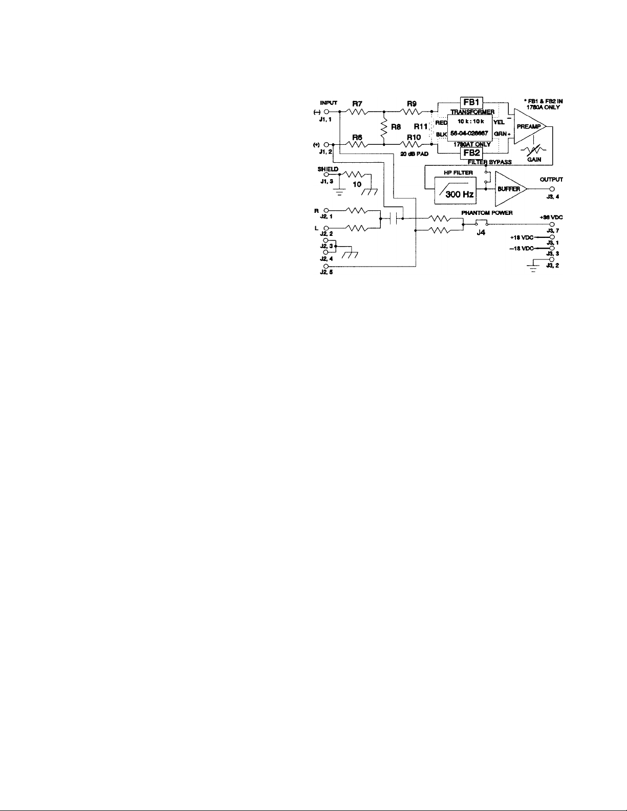
1780A/1780AT
Description
The Altec Lansing 1780A/1780AT Mic/Line Input
modules combine basic microphone preamplifi
cation with tme line level input capability. The
module heis a built-in resistive pad to permit levels
in excess of 0 dBu and its high input impedance
easily allows sixteen modules to be driven from a
single low impedance source. Also, the module
offers a 300 Hz high-pass filter, phantom power
capability, L -I- R stereo summing, and 0 to 50 dB
of continuously variable gain. Included in the
1780AT version is a 10 kii input bridging trans
former for those who prefer transformer isolation.
1780A/1780AT Specifications
Block Diagram of the 1780A/1780AT Input Module
Gain:
Input Sensitivity:
Without Pad: -68 dBu to -18 dBu
With Pad: -48 dBu to -1-2 dBu
Input Impedance:
1780A: lOkil
1780AT: lOkil
With 1793 Dual Phono: 40 kn
Frequency Response: 50 Hz - 20 kHz, ±1 dB
Total
Harmonic Distortion: (Ref. minimum gain,
1780A: <0.01%
1780AT: <0.025%
Equivalent Input Noise: <-120 dBr
0-50 dB, continuously
Vciriable
(.3 mVnns to 100 mVrms)
(3 mVrnis to 1 Vnns)
50 Hz - 20 kHz mecisurement
bandwidth, 30 kHz low-pass
filter)
(Ref. 0 dBr = 100 mVrms out
put, 10 kil load, 200 il input
termination, maximum gain,
A-weighted)
High Pass Filter:
Comer Frequency: 300 Hz
Slojje: 12 dB/octave
Controls: 1 - Gain, continuously
variable
Weight (Net):
1780A:
1780AT: 3.0 oz. (85 g)
Power Supply
Requirements: ±18VDCat 15maIX:
Included Accessories: 1 - 2-pin female jumper
2.5 oz. (70 g)
(supplied by meiinframe)
(for phemtom jxiwer)
2 - mounting screws
(for potentiometer bracket)
1 - Operating Instmctions
Page 4
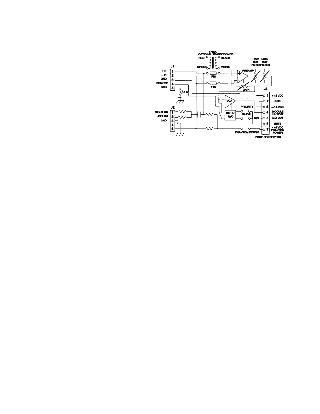
1781A/1781AT
Description
The Altec Lansing 1781A/1781AT Programmable
Input modules accepts either mic or line level
signals through a wide variety of connector inter
faces. Standard features include an electronically
balanced input stage with adjustable gain, continu
ously variable high and low pass filters, RFI protec
tion, 48 volt phaptom powering two levels of
muting, and remote volume control capability.
Programming with plug-in jumpers which may
select phantom power (on or off), mute priority or
slave, or remote volume control. The 1781AT
module also comes equipped with a 1785A Input
Isolation Transformer which provides an additional
10 dB of gain for improved sensitivity.
1781A/1781AT Specifications
Block Diagram of the 1781A/1781AT Input Module
Gain:
1781A: 0 dB - 50 dB,
continuously Vciriable
1781 AT: 10 dB - 60 dB,
continuously varicible
Input Sensitivity: (Ref. 1 kHz, 10 kfi load) Equivalent Input Noise:
1781 A: -68 dBu to -18 dBu
(0.3 mVrms - 100 mVrms)
1781 AT:
Input Impedance: (Ref. 1 kHz)
Electronically beilanced: >8 kfi
Transformer balanced:
With 1793 Dual Phono
Connector Installed: >39 kfi
Frequency Response: (Ref. 1 kHz, 100 mVrms
1781A:
±1 dB (minimum gaiin):
± 1 dB (maximum gain):
1781AT:
±1 dB (minimum g2un): 20 Hz - 20 kHz
±1 dB (meiximum gedn): 50 Hz - 15 kHz
-78 dBu to -28 dBu
(0.1 mVrms - 30 mVrms)
200 fl - 600 fi
output, 10 kfi load)
20 Hz - 20 kHz
50 Hz - 20 kHz
Total Harmonic
Distortion (THD): (Ref. 1 kHz, 100 mVrms
output, minimum gain, 10 kfi
load, 30 kHz low p>etss filter)
20 Hz - 20 kHz: <0.03%
(Ref. 0 dBr = 100 mVrms
output, 10 kfi load, 200 fi
input termination meiximum
getin, A-weighted)
<-120 dBr
High Pass Fiiter (Low Cut):
Comer Frequency: 320 Hz
Slope: 6 dB/oct (20 dB/dec)
Low Pass Filter (High Cut): (Ref. 100 mVrms output,
Comer Frequency: 5 kHz
Slope: 6 dB/oct (20 dB/dec)
Attenuation: (Ref. 100 mVrms output.
Mute:
(Ref. 100 mVrms output,
minimum geiin, 10 kfi load)
(>10dBat 100 Hz)
minimum gciin, 10 kfi load)
(>6 dB at 10 kHz)
minimum gain, 10 kfi load)
>60 dB
(10 kfi remote)
Page 5

1783
Description
Special Ordering Instructions
The Altec Lansing 1783 Line Output modules pro
vides the drive capability necessary to interface
with other professional equipment. The electroni
cally balanced output stage provides a low source
impedance to drive subsequent stages. If trans
former isolation is necessary,the module’s circuit
board accomodates the optional PC-mount 1786
Output Isolation Transformer. The continuously
vciriable output level control is local to the module
permitting independent adjustment of each line
output.
1783 Specifications
Output Source
Impedance:
Nominal Output Level
/Load Impedance:
Maximum Output
Level:
<50 n
+8 dBm
(Ref. 1 kHz, 0 dBm = 0.775
Vrms with 600 il load, output
level control at maximum, 100
mVrms input)
+24 dBm
NOTE: 77ie modules listed below are required
for use with the I707C/I7I5C and must be
ordered separate from the mainframe.
Plug-in Input Modules:
1780A Mic/Line Input module
1780AT Mic/Line Input module with 10 ki)
bridging transformer installed
1781A Programmable Input module
1781AT Programmable Input module with
model 1785A 600 H to 10 kfl
isolation transformer installed
1785A 600 n to 10 ki) Input Isolation
Transformer for installation on
existing model 1781A
Plug-in Output Module:
1783 Line Output module
1786 Output Isolation Transformer
Plug-in EQ Module:
875LA Programmable 14-Band EQ module
NOTE: Each module selected requires one of
the following connectors also be ordered:
Frequency Response:
±1 dB:
Total Harmonic
Distortion (THD):
20 Hz - 20 kHz:
Signal to Noise Ratio:
Power Requirements:
1786 Output Isolation Transformer
Impedance Ratio: 1:1 (600 il:600 Cl)
Frequency Response:
±1 dB:
Total Harmonic
Distortion (THD):
20 Hz - 20 kHz:
50 Hz - 20 kHz:
(Ref. 1 kHz, +8 dBm output)
20 Hz - 25 kHz
(Ref. 1 kHz, +8 dBm output,
output level control at maxi
mum, 30 kHz low peiss filter)
<0.05%
>88 dBm
(Below +8 dBm output, out
put level control at maximum,
A-weighted)
±18 VDC at 20 mA
(supplied by mainframe)
(Ref 1 kHz, +18 dBm output)
20 Hz - 20 kHz
Ref 1 kHz, +18 dBm output)
<0.5%
<0.1%
1791
Female XLE
1793
Dual RCA Phono
-.'■i.V ■■
1792
Male XLR
,K., /¡3^1... tif
v
1794
5- 1
Page 6
CONFIGURING THE MAINFRAME
The Mainframe's Inner Workings
USER INSTALLED STRAPS
1707C/1715C System Block Diagram
ARCHITECT'S and ENGINEER'S SPECIFICATION
The mixer/power amplifier shall have six configurable
ports and be capable of operating from 100,120, 200,
220, or 240 Vac, 50/60 Hz line, or from ±48 VDC.
Each port shall be usable vwth a microphone or other
high level device. The mixer/power amplifier mainfreune shedl include a compressor/limlter, low and
high frequency sheMng equalizers, and a tone
generator capable of producing general purpose and
emergency warning signals.
The power amplifier shall meet the following perfor
mance criteria: Power Output: 75 watts (1707C) at
less than 0.05% THD from 20 Hz to 20 kHz (8 il direct
output), or 150 watts (1715C) at less than 0.05% THD
from 20 Hz to 20 kHz (4 il direct output). Frequency
Response: 20 Hz to 20 kHz, ±I dB (direct output).
Source Impedance: 150 ft to 250 ft nominal with a
microphone preamplifier, 600 ft with a bridging
transformer, 150 ft to 600 ft with a line matching
transformer, and greater than 30 kft vwth a tape
preamplifier. Equivalent Input Noise: <-120 dBr with
M8V DC INPUT
a low impedance microphone preamplifier. Output
Noise: <-85 dBm (wth all controls off).
The mixer/power amplifier shall be rack mountable
and finished in black. The amplifier’s dimensions
shall be SVa" (H) x 19" (W) x \2Va” (D) and its net
weight shall be 24.2 lbs. (1707C), or 30.8 lbs.
(1715C).
The plug-in accessory modules shall be the 1780A/AT
and the 1781A/AT Input modules and the 1783 Une
Output module. The accessory transformers usable
with the modules shall be the 1785A Input Isolation
transformer and the 1786 Output Isolation transform
er. The connector subassemblies shall be the 1791
female XLR, 1792 male XLR, 1793 dual phono, and
the 1794 5-lug screw terminal connector.
The mixer/power amplifier shall be the Altec Lansing
Model 1707C/1715C.
a MARK IV company
P.O. BOX 26105 • OKLAHOMA CITY, OK 73126-0105 • U.S.A. • 405/324-5311 or FAX: 405/324-8981
© 1992 ALTEC LANSING CORPORATION
PRINTED IN U.S.A. 7/92 Revision 1
42-07-029244
Page 7

LAISISIISIG
/Ac Jid of
1707C & 1715C
Mixer/Power Amplifiers
Operating and Service Instructions
ALTEC LANSING CORPORATION
a MARK rV company
P.O. Box 26105 • OKLAHOMA CITY, OK • 73126-0105 • 405-324-5311 or FAX 405-324-8981
Page 8

Table of Contents
Section
SPECIFICATIONS
ELECTRICAL CONNECTIONS FOR THE 1707C/1715C
MIXER/POWER AMPLIFIERS
Power Connections (120 Volt, 50/60 Hz)
Power Connections (100, 200, 220, or 240 Volt; 50/60 Hz)
INSTALLING MODULES IN THE MAINFRAME
SHELF OR RACK MOUNTING THE 1707C/1715C
MIXER/POWER AMPLIFIERS
Ventilation
CONFIGURING THE MAINFRAME
The Mainframe’s Inner Workings
Output Connection
Output Fuse
Mute/Tone Generator Connections
The Rear-Panel Output-Level Control
Resistance Effects of Long-Cable Runs on Mute—
and Tone-Generator Circuits
LINK IN/LINK OUT Connections
PREAMP OUT/AMP IN Connections
AUX OUT Connections
Battery Input Connections
FRONT/REAR-PANEL CONTROLS, SWITCHES, INDICATORS,
AND CONNECTORS
INITIAL SETUP AND OPERATION OF MAINFRAME WITH
MODULES INSTALLED
Initial Setup of an Input Module
Initial Setup of an Output Module
Initial Setup of the Mainframe
Operating the 1707C/1715C Mixer/Power Amplifiers
SERVICE INSTRUCTIONS
SERVICE INFORMATION
Power Amplifier Bias Adjustment
Power Amplifier DC Offset Adjustment
Parts Ordering
Factory Service
Technical Assistance
Parts List
Page
3,4
5
5
5
6
6
6
7
7
8
8
8
8
8
8
8
9
9
10,11
10
10
10
10
10,11
13
14
14
14
14
14
14
15-18
List of Tables and Figures
Table I. AC Line Voltage Selection and Strapping Chart
Table II. AC Fuse Selection Chart
Table III. Maximum Allowable Cable Resistances
Figure 1. Top-Cover Removal
Figure 2. Location of Voltage Selection Terminal Block
Figure 3. Application of International Stickers
Figure 4. Module Installation
Figure 5. Removal of Blank Cover Panel
Figure 6. System Configuation Label
Figure 7. Block Diagram of 1707C/1715C Mixer/Power Amplifiers
Figure 8. Direct Output Connections
Figure 9. Transformer Output Connections
Figure 10. Mute/Tone Generator Switch Connections
Figure 11. Typical Linking Connections
Figure 12. Patching an External Equalizer or Other Signal Processing
Devices
Figure 13. Battery Input Connections
Figure 14. Front-Panel Controls, Switches, and Indicators for the
1707C/1715C
Figure 15. Rear-Panel Control and Connectors for the 1707C/1715C
Figure 16. Schematic of the 1707C/1715C Mainframe
5
5
8
5
5
5
6
6
6
7
8
8
8
9
9
10
11
Gatefold
Page 9

Description
The 1707C and 1715C Mixer/Power Amplifiers offer a will be muted,
highly flexible integration of a user configurable six input
mixer with a fully protected power amplifier in one con
venient cost effective package.
The six input ports accept any of the several input
modules or output module. The programmable input
modules may have their muting circuitry configured in
either "priority", "slave" mode, or may be set to ignore
muting commands. When a module configured in the
"Priority" mode is activated, modules in the "slave" mode
Specifications
Continuous
Average Power
1707C
1715C
Maximum Midband
Output Power
1707C
1715C
Power Bandwidth:
Direct Output:
Transformer Output:
Frequency Response:
Direct Output:
Transformer Output:
Link Output:
Preamp Output:
Total Harmonic Distortion (THD):
Direct Output: <0.05%, 20 Hz - 20 kHz
Transformer Output: <1.0%, 50 - 100 Hz
link Output: <0.05%, 20 Hz - 20 kHz
Preamp Output: <0.05%, 20 Hz - 20 kHz
Intermodulation Distortion: (SMPTE 4:1)
Direct Output: less than 0.1% at rated
Input Sensitivity / Input Impedance:
(For rated output power. Ref. 1 kHz, 0 dBu = 0.775 Vrms)
Using 1780A/1780AT:
(balanced, no pad)
Using 1780A/1780AT:
(balanced, w/pad)
Using 1781A:
(balanced)
Using 178 lAT:
(balanced)
Using 1781A-H785A:
(balanced)
75 watts
150 watts
(Reference 1 kHz at 1% THD)
100 watts
175 watts
(Ref. 1 kHz at rated output
power)
better than 20 Hz — 20 kHz
better than 50 Hz — 15 kHz
±1 dB, 20 Hz - 20 kHz
(Ref. 1 kHz, I watt output)
±1.5 dB, 50 Hz - 15 kHz
(Ref. 1 kHz, 1 watt output)
±ldB, 20 Hz - 20 kHz
(Ref. 1 kHz, 100 mVrms,
10 kil load)
±ldB, 20 Hz - 20 kHz
(Ref. 1 kHz, 0 dBm output,
600 n) load)
(Ref. 1 kHz, rated output
p>ower, 30 kHz low-p>iiss filter)
<0.1%, 100 Hz - 20 kHz
(Ref. 1 kHz, rated output
jxjwer, 30 kHz low-pass filter)
(Ref. 1 kHz, 100 mVrms
output, 10 kil load, 30 kHz
low-pass filter)
(Ref. 1 kHz, 0 dBm output,
600 fl load, EQ flat,
compressor/limiter off,
30 kHz low-p>ass filter)
power)
0.3 to 100 mVrms / 10 kil
(-68 dBu to -18 dBu)
3 mVrms to 1 Vrms / 10 kil
(-48 dBu to -f-2 dBu)
0.3 to 100 mVrms / 10 kil
(-68 dBu to -18 dBu)
0.1 to 30 mVrms / 600 il
(-78 dBu to -28 dBu)
0.1 to 30 mVrms / 600 il
(-78 dBu to -28 dBu)
Circuitry is also provided to allow remote volume
control of individual inputs.
Multiple mainframes may be dynamically linked
together. Separate preamp-out and amplifier-in jacks allow
the insertion of equalizers or other signal processing
between the mixer and the p)ower amplifier.
A multi-tone generator eind a compressor/limiter are
also provided.
Input Sensitivity / Input Impedance:
Link Input:
(unbalanced)
Amplifier Input:
(unbalanced)
Rated Output Level /
100 mVrms / 10 kil
(-18 dBu)
0.775 Vrms / 10 kil
(0 dBu)
(Reference 1 kHz)
Minimum Load
Impedance:
Link Output (unbal):
Preamp Output (unbal):
Auxiliary Output (unbal):
Direct Output:
1707C:
1715C:
Transformer Output:
1707C:
1715C:
100 mVrms (-18 dBu), 2 kil
0 dBm, 600 il min. load
0 dBm, 600 il min. load
Unbalanced
24.5 Vrms / 8 il min. load
24.5 Vrms / 4 il min. load
Balanced
17.4 Vrms / 4.0 il min load
25.0 Vrms / 8.3 il min load
70.7 Vrms / 66.6il min load
25.0 Vrms / 4.2 il min load
34.6 Vrms / 8.0 il min load
70.7 Vrms / 33.3il min load
Damping Factor:
Direct Output:
>40, 20 Hz - 1 kHz
Signal-to-Noise Ratio:
Direct Output:
(master at minimum)
Direct Output:
(master at maximum)
Link Output:
Preamp Output:
> 105 dB below rated
output power, A weighted.
>80 dB below rated output
power, A weighted.
>75 dB below 100 mVrms
output, A weighted.
>75 dB below 0.775 Vrms
output, A weighted,
EQ defeated, compressor /
limiter off.
Protection Systems:
Amplifier:
Load:
External DC Supply:
Mainframe:
Equalization:
Bass:
Treble:
Note: 0 dBm into 600 il yields 0.775 Vrms.
• Short circuit current
limiting.
• Over voltage limiting.
• Thermal Sensing.
• Spurious oscillatory
protection.
• Low AC line sensing.
• Output DC detection.
• Subsonic detection.
• Tum-on/tum-off
transients.
(approx 3 seconds)
• DC input fuses.
• AC line fuse.
Shelving Type.
±12 dB at 100 Hz.
±12 dB at 10 kHz.
Page 10

Compressor / Limiter:
Threshold:
Compression Ratio:
Release Time:
Tone Generator:
Control:
Level adjustment:
Connectors:
Inputs:
Amplifier Input:
Link input:
Battery:
Outputs:
Amplifier Output:
Preamp Output:
Link Output:
Auxiliary Input:
Control:
Mute and
Tone Generator:
Controls:
Front Panel:
Compressor/Limiter:
EQ Controls:
Output:
Miscellaneous: 1 AC Power switch
Rear Panel:
Tone Generator: 1 Output Level adjust
Indicators:
Front Panel:
Microphone
Phantom Power:
Power Requirements:
AC Mains:
1707C:
1715C:
Tones:
Input:
Feedforward Topology
-20 dB to -1-20 dB
Continuously variable.
(Ref.
too
input.)
1:1 to oo:l,
Continuously variable.
50 msec to 5 sec.
Continuously variable.
Electronically produced
Buzzer, siren, single-tone
chime, and repeating tone
chime.
All tones are initiated by
remote switch closures.
Rear panel.
1 — RCA phono receptacle
1 - RCA phono receptacle
3-teiminal barrier strip
7-terminaI barrier strip
1 - RCA phono receptacle
1 — RCA phono receptacle
1 — RCA phono receptacle
Screw Terminals (7)
6 Input Level adjust
1 Release Time adjust
(screwdriver slotted)
1 Threshold adjust
(screwdriver slotted)
1 Compression Ratio adjust
(screwdriver slotted)
1 On/Off Switch
1 Bass adjust
1 Treble adjust
1 EQ In/Defeat switch
1 Master Level adjust
(screwdriver slotted)
6 Green LED’s, (Nominal
Input Level)
6 Red LED’s, (Peak Input
Level)
1 Red LED, Main power
output CLIP)
1 AC Power ON
48 VDC @ 200 milliamps
consumption
(Ref. 1 kHz, rated output
with no modules installed
100, 120, 200, 220 or
240 VAC.
165 watts maximum.
100, 120, 200, 220 or
240 VAC.
320 watts maximum.
mVrms on Link
Power Requirements:
Battery:
1707C:
1715C:
±48 VDC bipolar,
1.5 amps maximum.
±48 VDC bipolar,
3.0 amps maximum.
Power Consumption and
Heat Produced:
1707C:
75 watts output:
25 watts output:
165 watts consumed.
306 BTU/hour.
130 watts consumed.
357 BTU/hour.
1715C:
150 watts output:
50 watts output:
320 watts consumed.
578 BTU/hour.
230 watts consumed.
612 BTU/hour.
Operating
Temperature Range:
Dimensions:
Width:
Height:
Depth:
Up to 50°C (122°F)
19 inches (48.3 cm)
5'/i inches (13.3 cm)
3 standard rack units.
13 inches (33.0 cm)
Net Weight:
I707C:
1715C:
Finish Color:
Indi
- Operating/Service Instruction documents. One
4
each for the Mainframe, 1780A/AT, 1781A/AT,
and 1783.
- Shorting Bar (Installed on Direct Output to
1
ОТ in).
- "U" Shorting Bar (Installed on Preamp Out to
1
Amp In).
- Rubber Feet (installed).
4
- System Configuration Label installed on top
1
cover.
- International fuse.
1
- International 220/240 VAC voltage sticker.
1
- International Fuse sticker.
1
- Rack mount hardware kit.
1
25 lbs. (11.4 kg)
32 lbs. (14.5 kg)
Black
Optional Input Output Accessory Modules:
1780A Mic/Line Input Module.
1780AT Mic/Line Input Module with 10 kfi
bridging transformer installed.
1781A Programmable Input Module.
1781AT Programmable Input Module with 1785A
600 П to 10 kfi isolation transformer installed.
1783 Line Output Module.
1785A 600 fi to 10 kfi Input Isolation
Transformer.
1786 600 fi to 600 fi Output Isolation
Transformer.
1791 Female XLR Connector.
1792 Male XLR Connector.
1793 Dual RCA Phono Connector.
1794 5-Lug Screw Terminals.
8751A Programmable 14 Band EQ Module.
Altec Lansing continually strives to improve their products
and performance. Therefore, specifications are subject to
change without notice.
Page 11

ELECTRICAL CONNECTIONS FOR THE
1707C/1715C MIXER/POWER AMPLIFIERS
Power Connections (120 Volt, 50/60 Hz)
The mainframe configuration for both mixer/
power amplifiers comes with the power trans
former's primary line voltage strapped for
The numbers in Table I correspond to the
numbered positions on the alternating cur
rent terminal block connector, which is ad
jacent to the power transformer. To select
a line voltage, install the colored primary
lead wires into the corresponding numbered
positions on the terminal block.
120-volt operation from the factory. Refer to
Table I for exact strapping details and other
voltage options.
Table I. AC Line Votage Selection and Strapping Chart
Primary
Line Transformer Primary Lead Color
Voltage WHITE YELLOW RED BLUE ORANGE
100 V
5 2 11 9 3
120 V 2 5 11 3 9
200V
220V
240V 2 5 7
-------------------------
Make sure the line voltage corresponds
with the selected line voltage power
rating BEFORE you connect the main
5 2 7 10 8
5 2 7 8 10
8 10
NOTE
---------------------------
Locate the voltage selection terminal
block between the side of the chassis and
the power transformer. Refer to Figure 2
for details.
frame to the alternating current line.
w >
o 2
Power Connections (100, 200, 220, or 240
Volt; 50/60 Hz)
o ni
^ X-
r.
Table II. AC Fuse Selection Chart
AC Line
Voltage
100V
120 V
200V 2.0 A/250 V
220V 2.0 A/250 V
240 V 2.0 A/250 V
----------------------------
AC Line Fuse
1707C
3.5 A/250 V
3.5 A/250 V
NOTE
1715C
7.0 A/250 V
7.0 A/250 V
4.0 A/250 V
4.0 A/250 V
4.0 A/250 V
------------------------------
Use of fuses other than those listed in
Table II will VOID THE WARRANTY.
6. If you connected the power transformer’s
primary leads for 200—, 220—, or 240—volf
operation, perform steps 7,8, and 9 below
to prevent future confusion and possible
damage fo the amplifier. Otherwise, pro
ceed with step 10 below.
7. Affix the supplied 220/240 VAC label above
the power cord and cover the 120 VAC
silkscreened designation.
8.
Affix the 2-amp fuse/1707C, (4-amp/
1715C) label over the original 3.5 amp/
1707C, (7-amp/1715C silkscreened des
ignation. Refer to Figure 3 for where to
place the fuse label.
You may change the mixer/power amplifier's
120-volt power connection to a 100—, 200—,
220—, or 240—volt power connection by re
strapping the power transformer’s primary
line voltage. Use the following procedure to
change the factory strapping to another line
voltage.
1. If you connected the mixer/power amplifier
to an alternating current power source,
disconnect it.
2. Remove and save the nine screws that
secure the mixer/power amplifier's top
cover. There are two screws near the
bottom of each side, two screws on top
near the rear edge of the front panel, and
three screws at the top edge of the rear
panel. Refer to Figure 1 for details.
Figure 2. Location of Voltage Selection
Terminal Block
While referring to Table I, disconnect the
primary lead wires from the terminal block.
Pull each wire firmly to disengage the push-
on connector. Then reconnect each lead
wire into its designated position on the
terminal block that corresponds to the de
sired line voltage. Press each connector
to snap into place.
Install the appropriate fuse value from
Table II.
Figure 3. Application of International Stickers
9. Replace the standard AC line fuse with the
2-amp fuse/1707C, (4-amp/1715C)
supplied. You should find the labels and
the fuse enclosed in the plastic bag with
this manual. Refer to Table II for an AC
fuse selection chart.
10. If you are not installing additional modules
in the mainframe right now, reinstall and
secure the top cover with the nine screws
previously removed in step 2 above.
-------------------------NOTE---------------------------
You can buy and install additional mod
ules into the mixer/power amplifier,
which has six ports that you can con
figure as input or output modules.
Figure 1. Top-Cover Removal
Page 12

INSTALLING MODULES IN THE
MAINFRAME
For detailed instructions on how to install ad
ditional input and output modules, you may
order the following operating instruction
manuals from our Order Entry Department:
P/N 42-02-027720 for the 1781A/AT
Mic/Line Input Modules
P/N 42-02-026653 tor the 1780A/AT
Mic/Line Input Modules
P/N 42-02-027721 for the 1783 Line
Out put Module.
1. Remove and save the two screws that
secure the access panel to the top cover.
Refer to figure 1 for details.
2. Plug the input or output module into one
of the six channel positions with the con
trols facing the rear as shown in Figure 4.
Secure the module with the two screws
provided.
On the top cover is a System Configuration
Label. Use it to indicate the module type,
configuration, and any options for future
reference. Write directly on the label with
a permanent marker. Refer to Figure 6 for
a display of this sample label.
INPUT
OUTPUT
NONE
MUTE SLAVE
PRIORITY
XFORMER
RVC
♦ 4 dBm
INPUT
OUTPUT
NONE
MUTE SLAVE
PRIORITY
XFORMER
RVC
OdBm
7
INPUT
OUTPUT
NONE
MUTE SLAVE
PRIORITY
XFORMER
RVC
7
INPUT
OUTPUT
NONE
MUTE SLAVE
PRORITY
XFORMER
RVC
Phantom
Pwr
-------------------------
NOTE
---------------------------
You may buy connector assemblies to
use for installing additional input/output
modules from ALTEC LANSING.
[Tf
И
INPUT
OUTPUT
NONE
MUTE SLAVE
РРЮР1ТТ
XFORMER
RVC
1
INPUT
OUTPUT
NONE
MUTE SLAVE
РРЮР1ТУ
XFORMER
RVC
Figure A. Module Installation
3. Remove the blank cover panel as shown
in Figure 5. Install the selected connector
assembly with the screws provided. Plug
the pigtail connector (from the main con
nector assembly) onto its appropriate male
mating connector on the module’s printed
circuit board.
Figure 5. Removal of Blank Cover Panel
Figure 6. System Configuration Labei
SHELF OR RACK MOUNTING THE 1707С/
1715C MIXER/POWER AMPLIFIERS
You may shelf mount or rack mount the main
frame. For shelf or countertop applications,
four rubber feet on the bottom of the chassis
will protect resting surfaces and provide
elevation for air flow underneath the unit. For
rack or cabinet applications, remove the four
rubber feet from the bottom of the chassis.
Then install the unit in the rack with the screws
and shoulder washers provided. The unit must
have 1.75" of blank space both above and
below it.
Ventiliation
The mixer/power amplifier generates minimal
heat during normal use. Although the amount
of generated heat is low, make sure the main
frame is properly ventilated to prevent an ex
cessive temperature rise. Because the output
power devices (transistors) are sensitive to
heat, you should not place the amplifier be
tween other heat generating equipment or
in areas where the ambient temperature ex
ceeds 50°C (122°F).
If you mount the mainframe in an equipment
rack or cabinet with other heat producing
equipment, provide adequate space between
the units. Otherwise, the equipment may
become too warm.
If a rack or cabinet contains several amplifiers,
you may need to check the ambient air
temperature. To determine the ambient air
temperature, operate the system until the
temperature stabilizes. Measure the ambient
air with a bulb-type thermometer held at the
bottom of the uppermost amplifier.
-CAUTION-
Don’t let the thermometer bulb touch
the metal chassis. The chassis might
be hotter than the ambient air.
CAUTION-
If the air temperature exceeds 60°C
(140°F), place the equipment farther
apart or install a blower to provide
air movement within the cabinet.
Make sure you don't block the airintake holes located on the bottom of
the chassis or the exhaust holes on
the top cover.
Page 13

CONFIGURING THE MAINFRAME
The Mainframe’s Inner Workings
MODULE OUT NOMINAL’ /
100mV RMS
Z IN = 10K
Note: Switches
not included
with mainframe
___
' '
PEAK
USER INSTALLED STRAPS
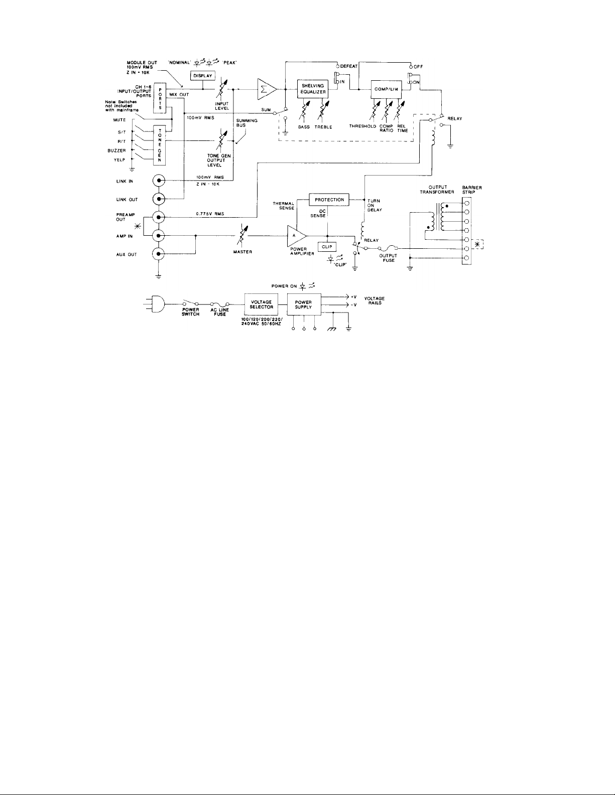
Figure 7 above displays a block diagram of
the mixer/power amplifier mainframe. Study
it carefully. To use the system's full capabil
ities, you'll need a good understanding of the
inner workings of the mainframe. Brief ex
planations of how the inside of the mainframe
works follow in the text below.
The signal coming from each additional input
module(likethe1781A, 1781AT, 1780A, or
1780AT) is simultaneously routed to the
mixer/power amplifier's front-panel nominal/
peak LED indicators and to the input channel
level controls. The dual LED nominal/peak
displays are pre-fader and designed to monitor
the output level from the corresponding
input module. The nominal (green) LED in
dicators have an approximate 10 dB window
over which they will illuminate. This makes
it easy to properly adjust the gain for each
input module while efficiently using the rest
of the system in terms of performance and
headroom.
/77
*48V DC INPUT
Figure 7. Block Diagram of 1707C/1715C
Mixer/Power Amplifiers
The mixer/power amplifier then sums the
signal at the wiper of each input channel
level control into a true virtual ground sum
ming node or bus. The summing amplifier
has eight input channels — input channels
one through six on the front panel, tone gen
erator output, and the link input or LINK IN
on the rear panel. The summing amplifier's
output signal drives the link output, or LINK
OUT, located on the rear panel of the main
frame. The E.Q. and compressor/limiter sec
tions are in series with each other, as shown
in Figure 7. The compressor/limiter s output
signal drives the preamplifier output, or
PREAMP OUT, located on the rear panel
which then provides the input signal to the
main amplifier section.
The BASS and TREBLE E.Q. controls are
ideally suited to make adjustments to the
overall response of the mix. The low and high
frequency shelving equalizers provide *12
dB of boost and cut with the maximum boost
occurring at 100 Hz and 10kHz, respectively.
The compressor/limiter section features
variable release time, compression ratio, and
threshold. The circuit uses a feed-forward
topology that will minimize level differences for
a more nearly constant output level. The
compression ratio can approach =>o:1, and the
attack time is fixed at approximately 10 ms.
The main amplifier section protects itself and
the load against radio frequency interference,
spurious oscillatory waveforms, excessive
temperatures, direct current, turn-on/turn-off
transients, and excess voltage/current phase
shift due to reactive loading.
A signal overload circuit monitors the level at
the output stage of the amplifier section. The
front-panel CLIP LED indicator illuminates
7
Page 14

when signal levels are high enough to cause
significant output clipping.
A dual slope V-l limiter protects the output
devices. It keeps the output devices operating
within their SOA (safe operating area) as de
fined by the device manufacturer.
A special integrated circuit function block
monitors the heatsink temperature, powersupply voltage, and the amplifier’s output
When it detects a problem, it immediately
disengages the output relay.
Output Connections
Make output connections to the seven-ter
minal barrier strip connector located on the
lower-left side of the mainframe's rear panel.
The 1707C main output connections include
an 8 Q direct output (24.5 vrms) and three
transformer balanced outputs; 4 Q (17.4
vrms), 25 vrms (8.3 Q), and 70.7 vrms (66.6 Q).
The 1715C main output connections include a
4 £2 direct output (24.5 vrms) and a 25 vrms
(4.2 Q), an 8 Q (34.6 vrms), and a 70.7 vrms
(33.3 Q ) balanced transformer output.
Refer to Figure 8 for a display of the direct
output connections and Figure 9 to see the
transformer output connections.
70V 2SV 4/1 COM IN -f~ -
R«mov« shorting bar ^ ^ | l_
Figure 8. Direct Output Connections
70V 25V 4H COM IN -F -
I
OT an
OT an
T T •
1 , .L_, i , : i.._ j
Insert shorting C
the unit. If the fuse continues to blow, check
the load to see if it shorted or is exceeding
the rated power consumption. If the problem
continues, have a qualified service technician
service the unit.
Mute/Tone Generator Connections
The seven-lug screw terminal connector lo
cated on the mid-left rear of the mainframe
provides access to the system mute and tone
generator. For connection details, refer to
Figure 10.
MUTE S/T BUZZER
COM
o
COM R/T
o o o o o o
YELP
rrrTTTl
External SPST switches
(not included with mainframe)
Figure 10. Mute/Tone Generator Switch
Connections
A switch closure between the mute and
common (COM) terminals will mute any input
modules configured in the s/ave mode. You
can use the remaining switches to select one
of the following sounds:
A single-tone chime (S/T),
A repeating-tone chime (R/T),
A buzzer, or
A yelp (siren).
For the duration of a tone, the tone generator
automatically mutes any input modules con
figured in the slave mode.
Output-Level Control: The tone generator's
output-level control is conveniently located
on the rear panel of the mainframe. To in
crease the tone generator’s output level, rotate
the screwdriver-slotted control shaft clock
wise.
Table III. Maximum Allowable Cable Resis
tances
Function
S/T Chime 13
R/T Chime 15.8
Buzzer
Yelp 8
Mute 8
LINK IN/LINK OUT Connections
The LINK IN/LINK OUT phono connectors on
the mid-rear panel of the mainframe permit
you to dynamically link two or more systems
together. If you require more channels, the
1707C/1715C mixer/power amplifiers are fully
compatible with 1700C mixer/preamplifier. For
more information on the 1700C mixer/
preamplifier, you may order the operating
instruction manual (P/N 42-02-029241) or the
specification sheet (P/N 42-07-029242) from
our Order Entry Department.
The signal appearing at the LINK OUT con
nector is the summation of all input channels
as mixed by the input channel level controls.
LINK IN is a direct input to a system’s mixing
amplifier; it’s also a seventh Input channel.
To link two units together, connect LINK OUT
of system one to LINK IN of system two. Sys
tem two will now control the mix of up to
twelve input channels. Please referto Figure
11 for typical linking connections.
The LINK OUT signal is not affected by
the compressor/limiter or the E.Q. cir
cuits.
-NOTE
8
Resistance
O
kO
kO
kQ
kO
kQ
Figure 9. Transformer Output Connections
To use a transformer balanced output, install
a U shorting bar between the direct (-L) out
put and the output transformer’s input (OT IN).
-------------------------NOTE
When using the output transformer, you
may use any combination of output
connections as long as the total con
nected load does not consume more
than 75 watts for the 1707C or 150
watts for the 1715C.
Output Fuse: A fuse in series with the output
of the amplifier section protects the amplifier
from excessive current consumption by a
load. If this output fuse blows, replace it only
with a fuse that matches the same type and
rating as silkscreened on the rear panel of
--------------------------
-------------------------
Optional External Mute, (connected at
the factory) allows external muting of
the tone generator. If disconnected,
the tone generator cannot be extern
ally muted.
Resistance Effects of Long-Cable Runs on
Mute/Tone Generator Circuits: Table III shows
the maximum allowable cable resistance (total
resistance) that the mixer/power amplifier
can support. Resistances greater than these
values, resulting from excessively long-cable
runs or small gauge wire, may cause the mute
or tone generator circuitry to fail to operate.
Please make sure all cable resistances are
less than the values shown in Table III.
NOTE
---------------------------
8
PREAMP OUT/AMP IN Connections
The PREAMP OUT signal is a mix of all input
channels processed by the compressor/limiter
and tone control circuits. Normally, you would
insert a Ushorting bar between the PREAMP
OUT and AMP IN phono connectors on the
rear panel. However, you can remove the
shorting bar to patch in an external equalizer
or other signal processing device with a pro
per level match of 0.775 vrms nominal. Figure
12 shows a typical application using an ex
ternal equalizer or other signal processing
device.
Page 15

INPUTS 1-6
1
----
>
1
__
)
1707C
System 1
Link Out Zone 1 Master
1
f
Zone 1
(inputs 1-e)
INPUTS 7-12
Stgnii
flow
cP
Link In
. Zone 2 .
o
1707C
System 2
Zone 2 Master
(inputs 1-12)
Figure 12. Patching an External Equalizer or
Other Signal Processing Device
AUX OUT Connections
The auxiliary output (AUX OUT) phono con
nector on the rear panel is wired directly
(internally) to the AMP IN phono connector.
You can use it to drive a second amplifier or a
tape recorder. Please refer to the 1707C/
1715C mixer/power amplifier's block diagram
shown in Figure 7.
Battery Input Connections
You can power a system from the battery input
connector for auxiliary operation or standby
switchover. The battery input connector is the
three-terminal barrier strip located on the
upper-left rear panel of the mainframe. The
system requires two ±48V DC battery power
sources.
T0 connect the battery backup system to the
three-terminal barrier strip, follow the three
steps shown in Figure 13.
Figure 11. Typical Linking Connections
O O
sup®
Rpmev* Citar Piatile Covar.
/; ?
S1ap(*)
(J
B> 0 0 0 (i
♦ COM
DC Power Sourcoa
!)
■=■ 4« VOC
Cermaci DC Powor Seureaa
aa Shewn.
Stop ®
Ro-lnalall Clear Plaatla
Proloetive Cover.
Figure 13. Battery Input Connections
Page 16

FRONT REAR-PANELS CONTROLS, SWITCHES, INDICATORS, AND CONNECTORS
Figure 14 below displays the front panel on the 1707C mixer/power amplifier with numbers that point
out each control, indicator, and switch. You can find the corresponding number and name/description
of each control, switch, or Indicator in the text below Figure 14. These controls, indicators, and
switches are identical on the
Figure 14. Front-Panel Control, Switches, and Indicators for the 1707C
1715C.
©-
¿
Name Function/Description
Item
POWER Switch Applies primary power Two-position push-push switch
1
ON LED Indicator Illuminates red display on POWER switch when you
2
3 CH 1-6 Controls
4 Green/Red Dual LED
Indicators
THRESHOLD Control COMPRESSOR/LIMITER
5
6 RELEASE TIME Control
7
COMPRESSION RATIO
Control
ON/OFF Switch Places compressor/limiter circuit in or out of the
8
9 BASS Control
10
TREBLE Control Continuously variable potentiometer. Provides boost
11
EO IN/DEFEAT Switch Two-position switch . DEFEAT position disconnects
12
MASTER Level Control
13
CLIP LED Indicator
for on/off mode
turn on power.
INPUTS
Continuously variable potentiometers graduated from
” to 0 dB. You can increase or decrease level
for each corresponding input channel. Rotate clockwise
to increase level and counterclockwise to decrease
level.
INPUT LEVEL
Displays nominal (green) and peak (red) indication for
each channel.
Continuously variable potentiometer. Determines the
level at which limiting begins.
Continuously variable potentiometer. Determines the
time required for the system to return to normal after
signal falls below threshold.
Continuously variable potentiometer. Determines the
amount of limiting that will occur when the input signal
level exceeds the threshold, as set by the THRESHOLD
control.
signal path
OUTPUT
Continuously variable potentiometer. Provides boost
or cut in bass response. You can obtain normal or flat
response at a zero setting. Rotate clockwise to boost
response or counterclockwise to cut response.
or cut in treble response. You can obtain normal or
flat response at a zero setting. Rotate clockwise to
boost response or counterclockwise to cut response.
BASS and TREBLE controls when appropriate for
application, such as Acousta-Voicing. EQ IN connects
the BASS and TREBLE controls.
Continuously variable potentiometer graduated from
“ to 0 dB. Use it to simultaneously increase or de
crease all input channels. Rotate clockwise to increase
level or counterclockwise to decrease level.
Illuminates when an internal signal overload circuit
detects high output signal levels that may cause output
clipping.
fa) ri?)
INITIAL SETUP AND OPERATION OF
MAINFRAME WITH MODULES INSTALLED
Initial Setup of an Input Module
You can buy and install the following input
modules from ALTEC LANSING:
The 1781A programmable input module. The
1781AT programmable input module with
1785A input isolation transformer, and
The 1780A and 1780AT mic/line input
modules.
To initially set up an input module, follow
these steps:
1 Rotate the input module s gain control to
the 12:00 o'clock (MID) position for plan
ned microphone inputs or to the MIN (fully
counterclockwise) position for line-level
inputs. If the input type is unknown, rotate
the gain control to the MIN position.
2. Rotate the high-cut (HF) filter to the FLAT
position.
3. Rotate the low-cut (LF) filter to the FLAT
position.
Initial Setup of an Output Module
You can buy the 1783 line output module
from ALTEC LANSING. This module can be
installed with or without the optional 1786
output isolation transformer (also available
from Altec Lansing).
To initially set up an output module, rotate
the output module’s output level control
(labeled GAIN on the rear panel) to the MIN
position.
Initial Setup of the Mainframe
1. Rotate the MASTER output level control
on the front panel of the mainframe to the
position (fully counterclockwise).
2. Setthecompressor/limiterON/OFF switch
to the OFF position.
3. Set the tone control EQIN/DEFEAT switch
to the DEFEAT position.
Operating the 1707C/1715C Mixer/Power
Amplifiers
1. Connect a source representative of the
type of input signal to one of the input
module positions, if any. Slowly rotate the
input module's gain control clockwise un
til the mixer/power amplifier's green LED
display ( — 10 dB) on the input-level frontpanel section fully illuminates. This is the
nominal level for providing the most effi
cient performance and headroom.
The mixer/power amplifier's red LED dis
play may briefly illuminate on signal
peaks. This is permissible as long as it
does not flash more than fifty percent of
the time. If it does, reduce the gain of the
input module by rotating its gain control
counterclockwise or use an external pad.
10
Page 17

Figure 15 below displays the rear panel on the 1707C mixer/power amplifier with numbers that point
out each connector or control. You can find the corresponding number and name/description of each
connector or control in the text below Figure 15. These connectors and controls are identical on the
1715C. Figure 15. Rear-Panel Control and Connectors for the 1707C
/ / / i \ \ \ \ \ \
© @®(©®(z)®®©(©
Item
1
Name
Access Holes
Function/Description
Permits access to the screwdriver adjustable controls
on the modules.
2 Blank Cover Panel
Covers connector mounting holes. Protects against
internal voltages when not using port and connector.
LINK OUT Connector
3
Combine two units together by connecting LINK OUT
of system one to LINK IN of system two. This is an
RCA-type phono connector.
LINK IN Connector
4
Provides a direct input to the amplifier. This is an RCA-
type phono connector (ref. 1 kHz, lOOmvrms).
PREAMP OUT Connector
5
Use to patch auxiliary equipment between unit's mixer
and power amplifier. PREAMP OUT is normally strapped
to AMP IN. The PREAMP OUT connector precedes the
front-panel MASTER level control. This is an RCA-type
phono connector.
AMP IN Connector
6
Provides a direct input to the amplifier. This is an RCAtype phono connector (ref. 1 kHz, .775 mvrms).
AUX OUT Connector
7
Provides an auxiliary output of the signal appearing
at the amplifier's input. This is an RCA-type phono
connector.
8 Seven-Lug Screw Terminal
Connector.
9 OUTPUT LEVEL Control
Permits connection of external switches to operate
the system's mute and tone generator circuits.
Increase the output level of the tone generator by
rotating the screwdriver-slotted control shaft
clockwise. To decrease the output level, rotate it
counterclockwise.
Seven-Terminal Barrier
10
Strip Connector
U Shorting Strip
11
Permits connection of various loads to the
amplifier.
Connects output of amplifier to input of output
transformer. When in place, use only the transformer
outputs.
12 OUTPUT FUSE
Protects load against excessive current from
amplifier. Replace only with the same fuse type
and power rating.
13 Battery Input Connector
Use to power system from battery supply for auxiliary
operation or standby switchover. Requires one ±48V DC
battery power source, 1.5 amps maximum for the
1707C and 3 amps for the 1715C.
14 AC FUSE
Protects against excessive current drain from an
alternating current source. Replace only with same
fuse type and power rating.
15
GND
The ground terminal lets you connect auxiliary
equipment to the mainframe.
NOTE-
The LED display precedes each frontpanel input-level control. As a result,
it will always indicate the nominal and
peak levels regardless of input channel
settings. Please refer to the mainframe
block diagram shown in Figure 7.
Once the gain is set for each input module
channel, rotate the front-panel input-level
channel controls (CH 1-6) on the mixer/
power amplifier to their 12:00 o’clock
(MID) position. Slowly increase the MAS
TER output level control on the front of
the mainframe until you hear a normal
operating level through the loudspeaker
system. Then readjust the input-level
channel controls slightly for the desired
mix or blend of signals.
Adjust the high-cut (HF) and low-cut (LF)
filters on the input module as needed for
the desired response. The widest possible
bandwidth occurs when you rotate both of
these controls to the FLAT position. This
is the best setting for music. However, in
speech-only channels, you should limit
the bandwidth to help reduce noise and
system feedback.
To use the mixer/power amplifier's output
tone-control section, move the two-posi
tion EQ IN/DEFEAT slide switch to the
EQ IN position. Then adjust the BASS
and TREBLE controls for the desired re
sponse. From a center or 12:00 o'clock
(MID) position, rotate either control clock
wise to boost response or counterclock
wise to cut response.
If using the tone-control section is inap
propriate for current applications, such as
Acousta-Voicing, move the EQ IN/DE
FEAT slide switch to the DEFEAT position.
This disconnects the BASS and TREBLE
controls.
To use the compressor/limiter section,
follow this procedure:
Move the slide ON/OFF switch to the ON
position.
Rotate the RELEASE TIME control to its
maximum position (full clockwise).
Rotate the COMPRESSION RATIO con
trol to minimum position (full counter
clockwise).
Rotate the THRESHOLD control to its
12:00 o’clock (MID) position.
Begin increasing the compressor/limiter
by rotating the COMPRESSION RATIO
control clockwise until you achieve the
desired amount of compression or limiting.
Since the amount of compression or
limiting depends on the incoming signal
level, you may need to readjust the
THRESHOLD control. To lower the trig
gering threshold, rotate the THRESHOLD
control counterclockwise. If the system re
quires a higher incoming signal level to
trigger the compressor/limiter, raise the
threshold by rotating the THRESHOLD
control clockwise.
11
Page 18

NOTE-
A high compression ratio and a low
threshold setting may decrease the
system's apparent loudness since peak
signals and parts of the nominal signal
may lie above the threshold. You can
correct this by raising the threshold
level; just rotate the
control clockwise.
6. If you installed the 1783 line output
module, adjust the output level control on
the 1783 for the desired output level. The
higher the output level, the better the
signal-to-noise ratio. However, too high a
level reduces the available headroom and
may cause premature clipping.
THRESHOLD
NOTE-
If you set the 1783'3 output level con
trol at its MAX (full clockwise) level, the
output level is -rSdBm. However, this
level only applies if you use a 100
mvrms reference level on the input of
the output module from the mix output
bus. It also only applies if you have a
balanced 600 U load.
Repair performed by other than auth
WARNING-
orized warranty stations (dealers) or
qualified service personnel shall void
the warranty period of this unit. To
avoid loss of warranty, see your near
est ALTEC LANSING authorized deal
er. You can also call ALTEC LANSING
CUSTOMER SERVICE authorized deal
er. You can also call ALTEC LANSING
CUSTOMER SERVICE directly at
405/324-5311, FAX 405/324-8981, or
write:
10500 W. RENO
OKLAHOMA CITY, OK 73128 U.S.A.
12
Page 19

sounA of
1707C/1715C
MIXER/POWER AMPLIFIERS
SERVICE INSTRUCTIONS
*** CAUTION***
No user-serviceable parts are inside: you may en
counter hazardous voltage within the chassis. Ser
vicing information contained within this document
is for use only by ALTEC LANSING Corp. authorized
warranty stations and qualified service personnel. To
avoid electric shock, DO NOT perform any servicing
other than that contained in the Operating Instruc
tions unless you’re qualified to do so. Refer all ser
vicing to qualified service personnel.
13
Page 20

SERVICE INFORMATION
---------------------
WARNING-------------------------
ALTEC LANSING recommends that
you do not modify its products. Such
modifications shall be at the sole ex
pense of the person(s) or company re
sponsible. Any damage to persons or
property resulting therefrom shall not be
covered under warranty or otherwise.
Power Amplifier Bias Adjustment
Figure 16, shown on the gatefold, is the
schematic of the mainframe. You'll need
trimpot SVR102, provided in this system's
package, to set the bias of the amplifier. You
should set the bias current to approximately 20
milliamps DC. To set the bias, use a batterypowered DC voltmeter capable of reading in
the millivolt range and follow the procedures
outlined below. If you must use an AC-pow
ered voltmeter, float the AC ground wire using
the appropriate adapter.
1. With the unit unplugged, remove the top
cover from the unit to expose the main
circuit board. See Figure 1 on page 5
for how to remove the top cover.
2. Connect the rated load impedance to the
direct output of the mixer/power amplifier
(8 ii for the 1707C, 4 Q for the 1715C).
3. Attach RED probe lead from the DC
voltmeter to the junction of R130 (0.27 Q
emiter resistor) and the emitter of Q117.
Refer to figure 16.
4 Attach the BLACK probe lead to the junc
tion of R130 (0.27 iJ emitter resistor) and
the anode of D403.
5. Locate SVR102 on the main circuit board.
Apply power and adjust SVR102 for a
reading of approximately 5.5 millivolts.
Power Amplifier DC Offset Adjustment
Set the POWER switch to the OFF posi
tion. Rotate the MASTER level control
fully counterclockwise to the “ position.
Connect the rated load impedance for the
unit to the direct output (8 Q for the 1707C,
4 O for the 1715C). Connect the DC volt
meter across the load.
Locate SVR101 on the main circuit board.
Apply power and adjust SVR101 for a
reading of 0.00 VDC±10mV DC.
Parts Ordering
To order replacement parts, refer to the parts
list. If part Is not included on parts list, note
the component designator from the schem
atic (or printed circuit board) and the com
ponent’s description. Then call 405/324-5311,
FAX 405/324-8981, or write:
ALTEC LANSING Replacement
Electronic Parts
P.O. Box 26105
Oklahoma City, OK 73126-0105 U.S.A.
Factory Service
If the unit requires factory service, ship the
unit prepaid in the original carton (or a wellpacked carton) to the following address:
ALTEC LANSING Customer
Service/Repair
10500W. Reno
Oklahoma City, OK 73128 U S A.
Please enclose a note that provides the fol
lowing information:
Any details describing the problem, and
the conditions under which the problem
occurred, such as where used, how used,
and so forth.
Failure to enclose any helpful information
may delay the processing of your service
order.
Technical Assistance
For applications assistance or other
technical information, call 405-324-5311,
FAX 405-324-8981, or write:
ALTEC LANSING Technical
Assistance
P.O. Box 26105
Oklahoma City, OK 73126-0105 U.S.A.
14
Page 21

DESIGNATOR
ALTEC PART
NUMBER
DESCRIPTION
DESIGNATOR ALTEC PART
NUMBER
DESCRIPTION
IC 001 17-01-124804 TA 7317 P
IC 201 17-01-0374081 GD 74HC 368
IC 301, 501 17-01-027463
IC 605 17-01-0374061 SSM 2120
IC 602 17-01-0374111 TD 62507 P
IC 601 17-01-122833 NJM 5532 DD
IC 701 17-01-0374121 NJM 2068 DD
1C 603, 604 17-01-0374071 KIA 7359 P
Q114, 115
(1715C)
Q114, 115
(1707C)
Q116, Q117
(1715C)
Q1I6, 117
(1707C)
QlOl-104, 107,
901
Q105, 106 48-03-0372371
Q108, Q109 48-03-0374361 NPN 2SC 2235 Y
QUO 48-03-124822 NPN 2SC 2238 Y
Qlll
QOOl, 408
Q409 48-03-0372731 PNP KTB 1366 Y
48-03-124821 NPN 2SC 3281
48-03-0377261 NPN 2SD 718 (1707C)
48-03-124820 PNP 2SA 1302
48-03-0377271 PNP 2SB 688 (1707C)
48-03-124824 NPN KTC 2240 BL
48-03-0372361 PNP 2SA 968 Y
48-03-0372721
NJM 4558 DD
(1715C)
(1715C)
PNP 2SA 965 Y
NPN KTD 2058 Y
D003-007, 012,
104, 601
DlOl, 102
D103-108, 201,
202, 301, 401-
403, 602, 603,
901, 902
D008, 009
DOlO, 001, 013 48-01-113386
D203
POWER LED
D903 39-01-0374021
CLIP LED,
D904
RLY A 45-01-0376821
RLY B 45-01-0373941
SWITCH
THERMAL
SWITCH
FOOl, 002
(1715C)
FI
(1715C)
48-01-027300
48-01-125214U IN 60
48-01-122601 IN 4148
48-01-0374001 ZENER UZ-24BM
48-01-0376801 ZENER UZ-5.6BM
39-01-0376811 REC KLR 208 2x5
39-01-0374031
51-02-0376831 SLIDE SSJ622
51-02-0374421
51-04-0374381
51-04-0376841
IN 4006
ZENER UZ-18BM
RED
LED SLR-54GG R5
GRE ROHM
LED SLR-54UR R5
RED ROHM
RELAY T90N1D12 1224
RELAY RY 24W-K DC
24V
T105 ARIUI
NB 31.8 mm 4A/250V
UL/CSA (1715C)
NB 31.8 mm 6A/250V
UL/CSA (1715C)
Q403 48-03-0376761 NPN 2SD 1302 R
Q113, 301, 407 48-03-0372751 PNP KTA 1015 Y
Q002, 003,
112, 201-203,
302, 401, 402,
404-406, 902904
D1 42-02-0375651 BRIDGE KBPC-25-04
DOOl, 002
(1715C)
DOOl, 002
(1707C)
48-03-026624 NPN 2SC 1815 Y
LUG TYPE
48-01-0376741 6A2 (1715C)
48-01-0376781 IN 5402 (1707C)
15
FI
(1707C)
F2
(17I5C)
F2
(1707C)
FOOl, 002
(1707C)
SVRIOI, 102
SVR601
VR901
51-04-0377281
51-04-0376851
51-04-0377291
51-04-0377341
47-06-0374391
47-06-0373991
47-06-0373951
SB 31.8mm 3A/250V
UL/CSA (1707C)
NB 31.8mm 7A/250V
UL/CSA (17I5C)
NB 31.8mm
3.5/V250V UIV CSA
(1707C)
NB 31.8 mm 2A/250V
UL/CSA (1707C)
SEMI 470B 10/5
SEMI CS 100KB 10/5
Ф 16 K161 MOO-20KA
Page 22

DESIGNATOR
ALTEC PART
NUMBER
DESCRIPTION
DESIGNATOR
ALTEC PART
NUMBER
DESCRIPTION
VR501, 502 47-06-0373961
VR503 47-06-0376861 <I) 16 K161 MOO-50KB
VR601
VR602
VR603 47-06-0376871
TONE LEVEL
ADJUST
R127-130 47-01-124825 WW CE 0.27il 5W R
ROOD, 006
R131 47-02-0374241 MO ion 3W W/COIL
R132 47-01-0372481 MO 4.7n 2W 5%
ROlO-012 47-01-0374171 WW CE 220n 5W R
R133
R015 47-01-0374131 MO 560n 2W 5%
R026, 213 47-01-0374261 MO 680n IW 5%
R028 47-01-0374141 MO IKn 2W 5%
47-06-0373971 <I> 12 K121 LOO-IOKA
47-06-0373981 4> 12 K121 LOO-
47-06-0376881 4> 16 lOKAxl
47-01-0372011 MO ion IW 5%
47-01-0376901 MO 270n IW 5%
4> 16 K161 MOO-
100KB CC
lOKRD
<I> 12 K121 LOO-
lOOKB CC
RlOl
R029, 030,
47-01-0371221 CF 1.5kn 1/5W 5%
47-01-0376961 CF 2.2kn 1/5W 5%
413, 416, 505,
506, 607
R909 47-01-0372531 CF 3kn 1/5W 5%
R618 47-03-0376971
CF 3.24kn 1/5W 1%
R415, 910, 911 47-01-0372541 CF 3.3kn 1/5W 5%
R008, 009,
47-01-0371661 CF 4.7kn 1/5W 5%
402, 905
R417, 305 47-01-0372551 CF 5.6kn 1/5W 5%
R627, 628,308
47-01-0371681 CF 7.5kn 1/5W 5%
Note: If Q302
is a
KTC1815(Y),
then R308 is: 47-01-0371251 CF 15kn 1/5W 5%
R319, 504
R002, 003,
47-01-0372561 CF 8.2kn 1/5W 5%
47-01-0371691
CF lOkn 1/5W 5%
119, 110-113,
208, 608-611,
630, 631, 904
R502, 702,
47-01-0371241 CF 12kn 1/5W 5%
706, 912
R027 47-01-124803 MO 1.2Kn IW 5%
R601, 602 47-01-0376911 CF 33n 1/5W 5%
R623 47-01-0376921 CF 47n 1/5W 5%
R114 47-01-0374221 CF 68n 1/5W 5%
R331 47-01-0371201 CF lOOn 1/5W 5%
R617, 619 47-01-0376941 CF 200n 1/5W 1%
RI15, 116, 906 47-01-0372521 CF 220n 1/5W 5%
R118, 120
(1715C)
R616 47-01-0376951 CF l.OOkn 1/5W 1%
R118, 120
(1707C)
R107
R105, 106,
123-126, 404
R606, 633 47-01-0373711 CF 1.2kn 1/5W 5%
47-01-0372101 CF 470n 1/5W 5%
(1715C)
47-01-0371221 CF 1.5 kn 1/5W 5%
(1707C)
47-01-0374231 CF 560n 1/5W 5%
47-01-0371211 CF Ikn 1/5W 5%
R017, 103,
47-01-0371251 CF 15kn 1/5W 5%
104, 108, 212
R621 47-03-0377001 CF15.0kn 1/5W 1%
R018
47-01-0371711 CF 18kn 1/5W 5%
R117 47-01-0371721 CF 20kn 1/5W 5%
R121, 122
(1715C)
R620, 626 47-03-0377011
R121, 122
(1707C)
ROOl, 022,
47-01-0374211 CF 20 kn 1/5W 5%
(1715C)
CF 30.Ikn 1/5W 1%
47-01-0372581 CF 47kn 1/5W 5%
(1707C)
47-01-0372571 CF 22kn 1/5W 5%
102, 403, 414
R330
R020, 204,
47-01-0373571 CF 27kn 1/5W 5%
47-01-0371741
CF 33kn 1/5W 5%
320,
R615 47-03-0377031
R908
47-01-0372851 CF 47kn 1/5W 5%
CF 39.2kn 1/5W 1%
16
Page 23

DESIGNATOR ALTEC PART
NUMBER
DESCRIPTION
DESIGNATOR ALTEC PART
NUMBER
DESCRIPTION
R023, 109, 47-01-0372581 CF 47kil 1/5W 5%
R019, 024,
47-01-0371751 CF 56kil 1/5W 5%
025, 507, 629,
632, 901, 707,
708, 701
R605 47-01-0373691 CF 75KO 1/5W 5%
R704, 705 47-03-0377041 CF93.1kil 1/5W 1%
R016, 304,
47-01-0371261 CF lOOkil 1/5W 5%
307, 310, 311,
315, 316, 318
R412
47-01-0372601 CF 120kD 1/5W 5%
R624 47-03-0377061 CF 162kil 1/5W 1%
R021, 203,
47-01-0372611 CF 220kD 1/5W 5%
209, 205-207,
210, 211, 301,
306, 410
R612 47-03-0377071 CF 267kil 1/5W 1%
R625 47-03-0377081 CF 316kil 1/5W 1%
R309 47-01-0372621
CF 330kil 1/5W 5%
R613 47-03-0377101 CF 330kO 1/5W 5%
R604 47-01-0371281
CF 470kil 1/5W 5%
R312 47-01-0373641 CF 560kil 1/5W 5%
R313 47-01-0373651
CF 680kil 1/5W 5%
cm, 112,
207, 409
C204
C018
C501, 507,
612, 701, 704,
705, 903
C019, 103,
105, 208, 401
C300, 316 15-01-027327 AF RSA 47^lF 25V
Clio 15-01-026641 AF RSA 47^lF 50V
C004, 005,
009, 010
COOO
C604, 614
coil, 012,
021, 022, 601,
602
C015 15-01-124503
C003 15-01-124501 AF RSA 100iiF lOOV
C007
COOl, 002
(1715C)
15-01-0372221 AF RSA 10[iF 50V
15-01-0377151 AF RSA 22jiF 16V
15-01-0371431 AF RSA 22 nF 25V
15-01-0373801 AF RSA 33 nF 16V
15-01-0377161 AF RSA 47jxF 16V
15-01-0371441 AF RSA 47 ^F 63V
15-01-0377171 AF NP 47jiF 25V
15-01-0374321 AF RSA lOOuF 16V
15-01-0372251 AF RSA lOOjiF 25V
AF RSA lOOjiF 50V
15-01-0374271 AF RSA 470 nF 50V
15-01-0374281
AF HM 6800 tiF 63V
(1715C)
R201, 202,
47-01-0373631 CF 1.5mil 1/5W 5%
215, 317
R314, 902
47-01-0373681 CF 2.2mfi 1/5W 5%
R302, 303, 603 47-01-0374151
COI 7 15-01-0372191
C016, 202,
15-01-124507 AF RSA IpF 50V
203, 311, 313,
605, 901, 902
C306
C609
15-01-0377111 AF RSA 3.3 jiF 50V
15-01-0377121
C607 15-01-0372211
ClOl, 112,
15-01-122935
606, 615
CF 3.3mil 1/5W 5%
AF RSA 0.47 nF 50V
AF RSA 4.7[iF 25V
AF RSA 4.7jiF 50V
AF RSA lOuF 35V
COOl, 002
(1707C)
C309, 310 15-02-0374291 M 0.0015 pF lOOV J
C504 15-06-0371391 M 0.0018 nF lOOV J
C206 15-06-0371401 M 0.003311F lOOV J
C308 15-06-0371941
C502, 503 15-06-0372851 M 0.018nF lOOV J
C312 15-06-0377191 M 0.033 ^lF lOOV J
C408 15-06-0372131 M 0.047jiF lOOV J
C305, 113 15-02-100109 M 0.1 ^F lOOV J
C303 15-06-0374321 M 0.22nF lOOV J
C702 15-02-100014
15-01-0377311 AF HM 4700 nF 63V
(1707C)
M 0.0056 jiF lOOV J
C 15pF 50V J
17
Page 24

DESIGNATOR ALTEC PART
NUMBER
DESCRIPTION
С104, 505,
603, 613
С106, 108,
109, 611
С506, 703
С102, 107,
299, 608, 616
С201, 205,
298, 301, 302,
402-404
С610
С315
Cl
РТ
(1715С)
РТ
(1707С)
ОРТ
(1715С)
15-02-107455
15-02-0372051 C lOOpF 50V J
15-02-107470 C 220pF 50V J
15-02-100304 C 0.001 pF 50V Z
15-02-0371791
15-02-0371641
15-02-0371651 C 0.1 pF 50V Z
15-02-0377241
56-08-0374411 POWER
56-08-0377321 POWER
56-07-0377251 OUTPUT
C 47pF 50V J
C 0.01 pF 50V Z
C 0.047 pF 50V Z
C 0.0047 pF 400VAC
TRANSFORMER
(1715C)
TRANSFORMER
(1707C)
TRANSFORMER
(1715C)
ОРТ
(1707С)
56-07-0377331 OUTPUT
TRANSFORMER
(1707C)
18
Page 25

SCHEMATIC
Page 26

SCHEMATIC
SEKVICE INFOMIATION
RF.aSTANCe >«LLlES ARt MDICATEO IN OHNS UNLESS OTHERWISE SRECIFCO.
( « «1.000. M 4,000.000)
■ cAPACiTAHce Mums are shown in microfarads unless ctherwise noted
(P < MCRO - MICROFARADS >
ALL VOLTASES ARE REFERCO TO OROUM) UNDER THE FOUOWIRO CONDITtOMS
OC NO SIONAL EXCEPT WHCTE INDICATED
■ — PRECAUTION
A) ALL COMPONENTS A MARRED MUST EE REPLACED ONLY WlTHORIGIMAL TYPE SPECrCD
B) ALL SOLDERING MUST BE DONE M A PROFESSIONAL MANNER USING SOLOCR WITH ROSIN CORE OF
OALL COVERS, SMELO AND IMSULATHG SPACERS MUST BE R9LACE0 BEFORE RETURNING
0) A 0AMA6S POWER SIMPLT CORD MUST BE REPLACED BEFORE ВЕПтНб TO CUSTOMER
tl DIELECTRIC TEST CONSISTING OF I2COV AC SO Hz IS TO BE APPLIED BETWEEN BOTH BUttES
--
RY THE MANUFACTURER, INKEL PA CORPORATION AND INSTALLED AS T« ORIGINAL, SPACERS
ROSIT10MEO «KAY FROM ADJACENT COMPONENTS WHERE APPLICAB.E.
APPLIANCE TO CUSTOMER
OF T« POWER SUPa» CCRO ATTACHMENT РШ6 JK> WE ЕХРОВв CONDUCTIVE BIRFACE OP
THE APPLIANCE FOR A РЕЯОО OF NOT LESS THAR ONE SECOND BEFORE NETURHMG
IN BLCCVES
7,0901 . KTC 2240<BL)
KTA BSSIrl
: KTC EESSTY)
ESC ZZSBFY)
. ESC SSBItO) - ITI9C
SS0 7IBI0) -(Tore
: ESA 002 10) ' I7I9C
EsesBBio) -iTOTc
: KTD E09B<T) IRES)
: KTBiseaor) (rcs)
, 0 SOI - 0E03,0401, e«0S ,0404 -
0 I : BRDOC OlODC PflSSE
ООО, 0002 ' «А2 - I7ISC
0005- 0007,002,0C»4,D60 IN 4O0B
OIOS-OIOB, 020,0202, OSO, D40 - D40S,
DOO, Ol, OB 1 2ENER I99M
D20S : ШШ S.BJW
0009,009 V4ENER 249M
I N»402 - ITOTC
OBCB, DBOS.OBO, 0902 : IN4I4B
1C 201 ; G074 нсэев
IC 50,901 : 4996 I DUAL OP AMP)
1C 70 I 206B ( DUAL OP AMP ]
ICBOl 99 32 (DUAL OP AMP)
IC 803,604 : ТА 7399P
К 602 : TD62907P
К 60S SSM 2120
>, »02-904,9(12 rrc 1»1»(Т
SU9 [9]
2 (б1
Page 27

EQUIPMENT 1 MIXER / AMPLIFIER
DRtmi CHECKED APPROVED DATE DRAWING NO
MODEL 17I5C {17070
90
9880192
6 4
 Loading...