

Page 1
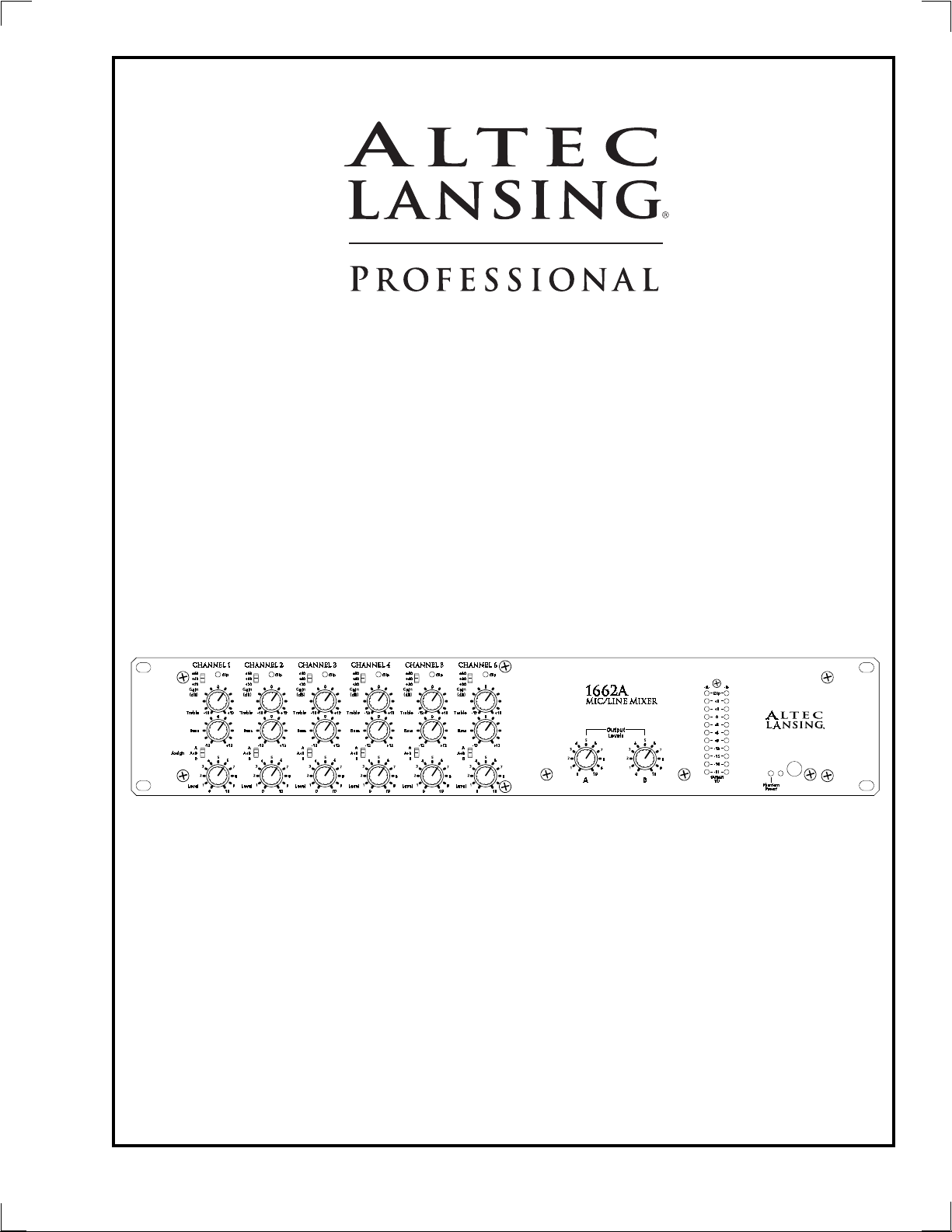
1662A
Mic/Line Mixer
Power
Altec Lansing PrAltec Lansing Pr
Altec Lansing Pr
Altec Lansing PrAltec Lansing Pr
1000 W. Wilshire Blvd. Suite 362
Oklahoma City, OK 73116 USA
A division of Altec Lansing Technologies Inc, Milford PA 18337-0277 Made In USA
ofessionalofessional
ofessional
ofessionalofessional
Page 2

Operating Manual -1662A Mic/Line Mixer
Table Of Contents
11
INTRODUCTIONINTRODUCTION
1
INTRODUCTION . . . . . . . . . . . . . . . . . . . . . . . . . . . . . . . . . . . . . . . . . . . . . . . . . . 3
11
INTRODUCTIONINTRODUCTION
22
UNPUNP
2
22
33
3
33
44
4
44
55
5
55
66
6
66
77
7
77
ACKINGACKING
UNP
ACKING . . . . . . . . . . . . . . . . . . . . . . . . . . . . . . . . . . . . . . . . . . . . . . . . . . . . . . 3
UNPUNP
ACKINGACKING
AC POWER REQUIREMENTSAC POWER REQUIREMENTS
AC POWER REQUIREMENTS . . . . . . . . . . . . . . . . . . . . . . . . . . . . . . . . . . . . . . . 3
AC POWER REQUIREMENTSAC POWER REQUIREMENTS
FRONT PFRONT P
FRONT P
FRONT PFRONT P
CONNECTORS AND CABLESCONNECTORS AND CABLES
CONNECTORS AND CABLES
CONNECTORS AND CABLESCONNECTORS AND CABLES
REAR PREAR P
REAR P
REAR PREAR P
TROUBLESHOOTING TIPSTROUBLESHOOTING TIPS
TROUBLESHOOTING TIPS . . . . . . . . . . . . . . . . . . . . . . . . . . . . . . . . . . . . . . . . . 7
TROUBLESHOOTING TIPSTROUBLESHOOTING TIPS
ANEL CONTROLSANEL CONTROLS
ANEL CONTROLS . . . . . . . . . . . . . . . . . . . . . . . . . . . . . . . . . . . . . . . . 4
ANEL CONTROLSANEL CONTROLS
. . . . . . . . . . . . . . . . . . . . . . . . . . . . . . . . . . . . . . . . . . . . . . . . . . . . . . . . . . . . . . . . . . . .
. . . . . . . . . . . . . . . . . . . . . . . . . . . . . . . . . . 5
. . . . . . . . . . . . . . . . . . . . . . . . . . . . . . . . . . . . . . . . . . . . . . . . . . . . . . . . . . . . . . . . . . . .
ANEL FEAANEL FEA
ANEL FEA
ANEL FEAANEL FEA
TURESTURES
TURES . . . . . . . . . . . . . . . . . . . . . . . . . . . . . . . . . . . . . . . . . . 6
TURESTURES
88
TYPICAL APPLICATYPICAL APPLICA
8
TYPICAL APPLICA
88
TYPICAL APPLICATYPICAL APPLICA
99
DIMENSIONSDIMENSIONS
9
DIMENSIONS . . . . . . . . . . . . . . . . . . . . . . . . . . . . . . . . . . . . . . . . . . . . . . . . . . . . . 8
99
DIMENSIONSDIMENSIONS
1010
SPECIFICASPECIFICA
10
SPECIFICA
1010
SPECIFICASPECIFICA
1111
WARRANTY INFORMAWARRANTY INFORMA
11
WARRANTY INFORMA
1111
WARRANTY INFORMAWARRANTY INFORMA
1212
BLOCK DIAGRAMBLOCK DIAGRAM
12
BLOCK DIAGRAM . . . . . . . . . . . . . . . . . . . . . . . . . . . . . . . . . . . . . . . . . . . . . . . 10
1212
BLOCK DIAGRAMBLOCK DIAGRAM
TIONSTIONS
TIONS . . . . . . . . . . . . . . . . . . . . . . . . . . . . . . . . . . . . . . . . . . . . . . . . . . 9
TIONSTIONS
TIONTION
TION . . . . . . . . . . . . . . . . . . . . . . . . . . . . . . . . . . . . . . . . . . . 8
TIONTION
TIONTION
TION . . . . . . . . . . . . . . . . . . . . . . . . . . . . . . . . . . . . . . . 9
TIONTION
2
Page 3

Operating Manual -1662A Mic/Line Mixer
1. INTRODUCTION1. INTRODUCTION
1. INTRODUCTION
1. INTRODUCTION1. INTRODUCTION
Congratulations on your purchase of an
Altec Lansing 1662A mic/line mixer, a
professional, studio quality solution to everday
mixing needs. The 1662A features six mic/line
inputs with mic input pad, TRS insert points, and
+48V phantom power. Each channel has up to
60dB input gain, separate treble and bass
controls, level, and an output channel assign
switch for sending any channel to either or both
outputs. Stereo sum inputs are provided for
adding typical program audio sources from DVD,
CD, tape, etc. A full 11 segment LED array
indicates stereo output level.
they were carefully designed to reduce to
minimum the possibility of transportation
damage should the unit again require packing
and shipping. In the event that damage has
occurred, immediately notify your dealer so that
a written claim to cover the damages can be
initiated.
The right to any claim against a public
carrier can be forfeited if the carrier is not
notified promptly and if the shipping carton and
packing materials are not available for
inspection by the carrier. Save all packing
materials until the claim has been settled.
Mic/line inputs and main outputs use
Euroblock connectors, allowing bare wire to be
easily connected to the mixer without soldering.
The 1662A mixer uses professional quality 16mm
metal shaft potentiometers for greater accuracy
and long life.
2. UNP2. UNP
2. UNP
2. UNP2. UNP
ACKINGACKING
ACKING
ACKINGACKING
As a part of our system of quality control,
every Altec Lansing product is carefully
inspected before leaving the factory to ensure
flawless appearance. After unpacking, please
inspect for any physical damage. Save the
shipping carton and all packing materials , as
The lightning flash with arrowhead
symbol, within an equilateral triangle, is intended to alert the user
to the presence of uninsulated
"dangerous voltage" within the
product's enclosure that may be of
sufficient magnitude to constitute
a risk of electric shock to persons.
TO REDUCE THE RISK OF ELECTRIC SHOCK, DO NOT REMOVE
COVER. NO USER SERVICEABLE PARTS INSIDE. REFER SERVICING TO QUALIFIED SERVICE PERSONNEL.
TO REDUCE THE RISK OF FIRE OR ELECTRICAL SHOCK,
DO NOT EXPOSE THIS APPlIANCE TO RAIN OR MOISTURE.
CAUTION
RISK OF ELECTRIC SHOCK
DO NOT OPEN
3. AC POWER REQUIREMENTS3. AC POWER REQUIREMENTS
3. AC POWER REQUIREMENTS
3. AC POWER REQUIREMENTS3. AC POWER REQUIREMENTS
The 1662A mixer will perform normally
from 93 to 125 volts AC, 50-60Hz (some export
models are wired for 240 Volts and are labeled
accordingly). Use only properly grounded AC
receptacles. To reduce the risk of ground loop
hum, use a central point for system AC power
distribution. In the event of an internal fuse
failure, refer this unit to a qualified service
technician for fuse replacement using only the
same type fuse, 0.5A Bussman AGC-1/2 or
equivalent. Power consumption is less than 20
watts.
The exclamation point within an
eqilateral triangle is intended to
alert the user to the presence of
important operating and maintenance instructions in the literature
accompanying the device.
TO REDUCE THE RISK OF FIRE, REPLACE ONLY WITH SAME
TYPE FUSE. REFER REPLACEMENT TO QUALIFIED SERVICE
PERSONNEL.
WARNING:
THIS APPARATUS MUST BE EARTHED
3
Page 4

Operating Manual -1662A Mic/Line Mixer
4. FRONT P4. FRONT P
4. FRONT P
4. FRONT P4. FRONT P
4.1 Input Gain4.1 Input Gain
4.1 Input Gain
4.1 Input Gain4.1 Input Gain
This three position switch sets the
operating level of the input preamp to +20db,
+40dB, or +60dB. Best signal to noise ratio is
obtained with higher gain settings. It is
therefore desirable to set the gain switch as high
as possible while still leaving 20dB of headroom
for signal peaks. Line level inputs will likely use
a setting of +20dB, while mic inputs generally
require a setting of +40dB for close mic
applications, and +60dB for quieter signals. If a
channel's clip LED is blinking, first turn down
that channel's level control. If the clip LED is
still flashing, turn down the input gain.
4.2 Clip Indicator4.2 Clip Indicator
4.2 Clip Indicator
4.2 Clip Indicator4.2 Clip Indicator
Input Clip LEDs are peak sensitive and
monitor all critical points within the input
channel. The clip LED turns on whenever any
portion of the audio path within the input
channel reaches a level 3 dB below actual
clipping. Clipping in the 1662A occurs at +23dB.
4.3 T4.3 T
rr
eble and Bass Contreble and Bass Contr
4.3 T
r
eble and Bass Contr
4.3 T4.3 T
rr
eble and Bass Contreble and Bass Contr
These controls are used for broad EQ
changes to each input channel. Channel EQ
consists of a high shelf control (treble) at 8KHz,
and a 90Hz low shelf control (bass). EQ boost or
cut is ±12dB at these frequencies.
ANEL CONTROLSANEL CONTROLS
ANEL CONTROLS
ANEL CONTROLSANEL CONTROLS
SwitchSwitch
Switch
SwitchSwitch
olsols
ols
olsols
4.4 Input Assign Switch4.4 Input Assign Switch
4.4 Input Assign Switch
4.4 Input Assign Switch4.4 Input Assign Switch
This switch selects the output routing for
each input channel. Each input can be routed to
Output A, B, or both.
4.5 Input Level Contr4.5 Input Level Contr
4.5 Input Level Contr
4.5 Input Level Contr4.5 Input Level Contr
This knob adjusts the level of each
channel. If a channel's level control is always
turned up to 9 or more, try increasing the gain
first. Conversely, if the level control is
consistently turned down to 1 or less, decrease
the gain setting first. Remember that the gain
setting should be set as high as possible while
still allowing 20dB of headroom.
4.6 Output Level Contr4.6 Output Level Contr
4.6 Output Level Contr
4.6 Output Level Contr4.6 Output Level Contr
These two controls determine the signal
level to the "A" and "B" outputs. They are used
to drive power amplifiers for the main
loudspeakers, or to connect to a stereo
recording device.
4.7 Output Meters4.7 Output Meters
4.7 Output Meters
4.7 Output Meters4.7 Output Meters
A pair of peak reading 11 segment LED
meters are used to indicate stereo output level
in VU. 0 VU is equivalent to +4 dBu (1.228Vrms).
Green LED's are used below 0 VU, yellow
above 0 VU and two red LED's indicate clipping.
The clip LED's turn on 3dB below actual
olol
ol
olol
olsols
ols
olsols
4
Page 5

Operating Manual -1662A Mic/Line Mixer
Power
clipping, detecting excessive signal level on any
critical audio path within the master section. If
all outputs are turned down and there is still
clipping, then one or more inputs needs to be
turned down.
4.8 Phantom Power LED4.8 Phantom Power LED
4.8 Phantom Power LED
4.8 Phantom Power LED4.8 Phantom Power LED
The phantom power switch is on the back
panel. When the switch is pressed in, the LED is
lit and +48VDC is applied to all six mic inputs for
use with condenser microphones. If there is a
mix of both condenser and dynamic
microphones, the phantom power will not affect
the operation of the most dynamic mics. The
phantom power voltage ramps up gradually to
minimize any turn-on "pops".
5. CONNECTORS AND CABLES5. CONNECTORS AND CABLES
5. CONNECTORS AND CABLES
5. CONNECTORS AND CABLES5. CONNECTORS AND CABLES
The 1662A mixer is fitted with three types
of audio connectors: 3-pin Euroblock assemblies
are used for mic/line inputs and main outputs, 1/
4" tip-ring-sleeve (TRS) phone jacks are used for
individual channel insert points, and RCA jacks
are used for sum inputs.
construction. This type of cable should be used
for all portable applications. Snake cables
containing multiple shielded pairs can be used
for a permanent installation, but must be
handled very carefully because the leads tend to
be fragile, and a broken conductor is difficult to
repair.
If low level and high level lines are run
parallel for long distances, crosstalk may occur.
In fact, the crosstalk (signal leakage between
cables) can cause an electronic feedback loop,
oscillation, and possibly damage to the
equipment. To minimize crosstalk, physically
separate low level (microphone) cables from
speaker cables by the greatest feasible distance.
At any point where cables meet, run low level
cables perpendicular to high level or speaker
cables. If low and high level or speaker cables
must be run parallel and in close proximity to
one another, they should be bundled separately.
In a permanent installation, avoid running
speaker cables and mic cable through the same
conduit pipe.
Two-conductor (twisted pair) shielded
cable is best for all audio connections that use
Euroblock assemblies. Belden No. 8412 or its
equivalent is an excellent cable due to its heavy
5
Page 6

Operating Manual -1662A Mic/Line Mixer
y
6. REAR P6. REAR P
6. REAR P
6. REAR P6. REAR P
6.1 Micr6.1 Micr
6.1 Micr
6.1 Micr6.1 Micr
ANEL FEAANEL FEA
ANEL FEA
ANEL FEAANEL FEA
ophone Inputophone Input
ophone Input
ophone Inputophone Input
TURESTURES
TURES
TURESTURES
The 1662A microphone input is an active
balanced type with a nominal impedance of
1200 ohms. Its noise performance is best with a
200 ohm microphone. The mic input connector
is a 3-pin Euroblock with the shield on (G), the
(+) in-phase connection on (+), and the (-) outof-phase connection on (-). If the input is
unbalanced, or single ended (meaning there is
only one signal wire with a shield) connect the
signal wire to (+), and connect the shield to
both
(-) and (G).
G
-
+
Euroblock
Connector
stem
S
G
-
+
6.3 Channel TRS Insert6.3 Channel TRS Insert
6.3 Channel TRS Insert
6.3 Channel TRS Insert6.3 Channel TRS Insert
A 1/4" stereo phone jack insert point
allows a device such as a remote level
controller, graphic equalizer, noise gate,
compressor/limiter, or direct out recording
device to be used with one or more input
channels.
The 1662A TRS (tip-ring-sleeve) insert
jacks use the tip for output and ring for the
returning input. These signals will be
unbalanced, so cable length should be at a
minimum to maintain low noise.
To use the TRS insert as a Direct Line
Output (pre EQ) for recording individual
channels,
make a special cable with tip and ring
connected at the 1662A end and a tip-sleeve
mono plug at the other end.
Connecting tip
and ring at the mixer insert jack is necessary for
uninterrupted signal within the mixer when
using direct line outputs.
Tip
Ring
Sleeve (Ground)
Stereo Phone Plug
6.2 Input Pad6.2 Input Pad
6.2 Input Pad
6.2 Input Pad6.2 Input Pad
The input pad is a 20dB attenuation
switch for extremely loud microphone or line
level inputs. It should normally be left in the
"out" position for best signal to noise ratio, but
can be used when the input is being clipped
with the gain and level control at minimum.
6
6.4 Sum Inputs6.4 Sum Inputs
6.4 Sum Inputs
6.4 Sum Inputs6.4 Sum Inputs
The RCA sum inputs on channels five and
six are typically used for auxillary audio sources
such as a disc or tape player, summing a stereo
source into a mono signal for each channel's
input. Using the sum inputs does not prevent
Page 7

Operating Manual -1662A Mic/Line Mixer
the use of mic inputs on channels five or six, but
only one level controls both the mic and RCA
inputs. The RCA sum inputs have a nominal
operating level of -10dBu to match most
consumer audio sources.
6.5 Outputs6.5 Outputs
6.5 Outputs
6.5 Outputs6.5 Outputs
The Euroblock "A" and "B" outputs are
controlled by the output level master controls.
They are active servo-balanced with a nominal
operating level of +4dBu into any load, and are
capable of driving long lines. Outputs can be
used balanced or unbalanced. For unbalanced
output, connect the shield to
6.6 +48V Phantom Power Switch6.6 +48V Phantom Power Switch
6.6 +48V Phantom Power Switch
6.6 +48V Phantom Power Switch6.6 +48V Phantom Power Switch
This switch applies +48VDC to all six mic
inputs for condenser microphones. Phantom
power will not affect most dynamic mics, which
may be used along with condenser mics.
7. TROUBLESHOOTING TIPS7. TROUBLESHOOTING TIPS
7. TROUBLESHOOTING TIPS
7. TROUBLESHOOTING TIPS7. TROUBLESHOOTING TIPS
7.1 No Sound7.1 No Sound
7.1 No Sound
7.1 No Sound7.1 No Sound
Check the AC power. Is the power switch
on? Check the level meters. If they are
operating, the problem is between the mixer
and the later components in the system. If there
is no meter activity, check to see that you really
have an input signal and that it is on the desired
channel.
7.2 Distorted Sound7.2 Distorted Sound
7.2 Distorted Sound
7.2 Distorted Sound7.2 Distorted Sound
Something is being overdriven in the signal
path. If the clip indicators are active, reduce the
both
(-) and (G).
channel gain and/or press in the pad switch on the
rear panel. There are many gain adjustments in
the mixer itself and probably several others in
other system components which makes it possible
to overdrive an input section and then incorrectly
try to reduce the gain of the output section. The
best way to approach setting gains is to establish
the operating level of input stages first by setting
their gain as high as possible but leaving about
20dB of headroom for loud peaks, then move on to
set the master gain to produce a good meter
reading. Proceed to set the gain of equalizers,
limiters, crossovers, and amplifiers following the
mixer in the same manner, always working toward
the later stages of the system.
7.3 Excessive Noise7.3 Excessive Noise
7.3 Excessive Noise
7.3 Excessive Noise7.3 Excessive Noise
If the noise is in the form of hiss, the
problem is usually due to an input stage set for
insufficient gain and then compensating for it
by increasing the level. Try increasing gain and
reducing level. Also, check that the -20dB rear
panel pad switch is not unnecessarily enabled.
7.4 Excessive hum7.4 Excessive hum
7.4 Excessive hum
7.4 Excessive hum7.4 Excessive hum
This is usually caused by "ground loops"
in the system wiring. A complex sound system
with many sources separated by significant
distance and using several power outlets has
many opportunities for this problem to occur. If
possible, every component in the system should
be plugged into the same AC circuit with a
common ground. Use balanced input and
output connections between widely separated
components.
7
Page 8

Operating Manual -1662A Mic/Line Mixer
8. TYPICAL APPLICA8. TYPICAL APPLICA
8. TYPICAL APPLICA
8. TYPICAL APPLICA8. TYPICAL APPLICA
TION:TION:
TION:
TION:TION:
In the setup shown here,
the 1662A is used to mix typical
sound sources that might be found
in a church, small club, gym, school
theater or similar environment.
Channels 1-4 are used for vocal
microphones, while the remaining
two channels are used for stereo
program tracks. "B" output is used
for main loudspeakers, and "A"
output is used for speakers in
another location, such as ceiling
speakers in a hallway.
Sum Inputs to
Channels 5 & 6
70 Volt Distributed
Sound System Amp
VCR, CD, DVD Player
Audio Output
Accompaniment Tracks
Cassette Player
Four Vocal
Mic Inpu ts
1662A
Mic/Line
Mixer
Hallway
Ceiling
Speakers
3.50 ( 88.9)
3.25 (82.5)
0.25 (6.3)
0.00
9. DIMENSIONS:9. DIMENSIONS:
9. DIMENSIONS:
9. DIMENSIONS:9. DIMENSIONS:
0.00
0.25 (6.3)
1662A Small Sound Reinforcement System
Altec Lansing 1662A
EQ,
Limiter,
Crossover,
Amplifier,
etc.
18.75 (476)
19.00 (483)
Full Range
Loudspeaker
6.50 (165)
8
Page 9

Operating Manual -1662A Mic/Line Mixer
10. SPECIFICA10. SPECIFICA
10. SPECIFICA
10. SPECIFICA10. SPECIFICA
DISTORDISTOR
DISTOR
DISTORDISTOR
THD at +4 dBu, 20Hz-20KHz . . . . . . . . . . . . . . . . . . . . . <0.01%
IMD (SMPTE) at +4dBu . . . . . . . . . . . . . . . . . . . . . . . . . <0.01%
HUM & NOISE (20Hz-20KHz at max prHUM & NOISE (20Hz-20KHz at max pr
HUM & NOISE (20Hz-20KHz at max pr
HUM & NOISE (20Hz-20KHz at max prHUM & NOISE (20Hz-20KHz at max pr
Equivalent input hum and noise . . . . . . . . . . . . . . . <-127dBu
Residual output noise,
all levels at minimum . . . . . . . . . . . . . . . . . . . . . . . . . . <-98dBu
Residual output noise, master at nominal,
all channel levels at minimum . . . . . . . . . . . . . . . . . . <-95dBu
MAXIMUM VOLMAXIMUM VOL
MAXIMUM VOL
MAXIMUM VOLMAXIMUM VOL
MASTER
Mic/Line Input to Master Outputs . . . . . . . . . . . . . . . . . +84dB
Sum Input to Master Output . . . . . . . . . . . . . . . . . . . . . +24dB
MAXIMUM LEVELSMAXIMUM LEVELS
MAXIMUM LEVELS
MAXIMUM LEVELSMAXIMUM LEVELS
Input level, +20dB gain, pad in . . . . . . . . . . . . . . . . . . +22dBu
RCA input level . . . . . . . . . . . . . . . . . . . . . . . . . . . . . . . . +10dBu
Output level . . . . . . . . . . . . . . . . . . . . . . . . . . . . . . . . . . +23dBu
FREQUENCY RESPONSEFREQUENCY RESPONSE
FREQUENCY RESPONSE
FREQUENCY RESPONSEFREQUENCY RESPONSE
20Hz-20KHz . . . . . . . . . . . . . . . . . . . . . . . . . . . . . . . .+0.5/-1.0dB
TIONTION
TION
TIONTION
TIONSTIONS
TIONS
TIONSTIONS
TT
AGE GAIN AGE GAIN
T
AGE GAIN (±2dB)
TT
AGE GAIN AGE GAIN
eamp gain)eamp gain)
eamp gain)
eamp gain)eamp gain)
PEAK INDICAPEAK INDICA
PEAK INDICA
PEAK INDICAPEAK INDICA
Peak Clip indicator on each input channel and left and right
outputs, illuminates 3dB below clipping
PHANTOM POWERPHANTOM POWER
PHANTOM POWER
PHANTOM POWERPHANTOM POWER
+48 VDC applied to all Mic Inputs, switchable on rear panel.
Maximum total current draw = 60mA. Maximum single
channel current draw = 10mA. Gradual power-up and down
to eliminate "pops".
WEIGHTWEIGHT
WEIGHT
WEIGHTWEIGHT
12 lbs. (5.5kg) Shipping
10 lbs. (4.5kg) Net
POWER REQUIREMENTSPOWER REQUIREMENTS
POWER REQUIREMENTS
POWER REQUIREMENTSPOWER REQUIREMENTS
120 VAC nominal, 93 VAC minimum, 50-60 Hz,
20 watts (240 VAC available)
*unless otherwise stated, specification conditions are: 150Ω
source, Gain switch set at "+40", all other controls set at
nominal.
TORSTORS
TORS
TORSTORS
11. W11. W
11. W
11. W11. W
ARRANTY INFORMAARRANTY INFORMA
ARRANTY INFORMA
ARRANTY INFORMAARRANTY INFORMA
TIONTION
TION
TIONTION
The unit you have just purchased is protected by
a limited five-year warranty . For warranty service or to
obtain a return RMA number, please call Altec Lansing
technical services at 405-848-3108. Fill out the information below for your records.
EQUALIZAEQUALIZA
EQUALIZA
EQUALIZAEQUALIZA
Bass . . . . . . . . . . . . . . . . . . . . . . . . . . . . . . . . . . . . ±12dB at 90Hz
Treble . . . . . . . . . . . . . . . . . . . . . . . . . . . . . . . . . ±12dB at 8KHz
CROSSTCROSST
CROSST
CROSSTCROSST
Adjacent inputs, 20Hz-20KHz . . . . . . . . . . . . . . . . . . . . <-70dB
VU METERSVU METERS
VU METERS
VU METERSVU METERS
Stereo outputs . . . . . . . . . . . . . . . . . . . . . . . . . . . -21 to +6 VU
0VU = +4dBu
TION (shelving)TION (shelving)
TION (shelving)
TION (shelving)TION (shelving)
ALKALK
ALK
ALKALK
Model Number _______________________________
Serial Number ________________________________
Dealer ________________________________________
______________________________________________
Date of Purchase ______________________________
Dealer’s Address ______________________________
______________________________________________
______________________________________________
Dealer’s Phone ________________________________
Salesperson ___________________________________
______________________________________________
9
Page 10

Operating Manual -1662A Mic/Line Mixer
g
g
12. 1662A Block Diagram12. 1662A Block Diagram
12. 1662A Block Diagram
12. 1662A Block Diagram12. 1662A Block Diagram
Input Channels 1-4
Mic Gain
+20 +40 +60
Mic
Input
Mic
Preamp
-20dB
Pad
Insert
Point
Input Channels 5-6
Mic Gain
+20 +40 +60
Channel
EQ
Level
+12dB max
0dB Mid
Bass Treble Level
Input
Clip
Indicator
Output
Assi
Input
Clip
Indicator
n
A
A+B
B
Output A
Output
5
+12dB max
+1.6dB Mid
Output B
Output
5
+12dB max
+1.6dB Mid
Level
Level
Level
Level
Output
Meters
Servo-
Balanced
Output
Output
Meters
Servo-
Balanced
Output
+
-
G
+
-
G
Mic
Input
Insert
Point
Sum
Input
Phantom
Power
-20dB
Pad
R
L
Mic
Preamp
EQ
Bass Treble Level
5
+48V To All
Mic Inputs
Channel
Level
+12dB max
0dB Mid
Output
Assi
n
A
A+B
B
10
Page 11

Operating Manual -1662A Mic/Line Mixer
11
Page 12

Operating Manual -1662A Mic/Line Mixer
Altec Lansing ProfessionalAltec Lansing Professional
Altec Lansing Professional
Altec Lansing ProfessionalAltec Lansing Professional
1000 W. Wilshire Blvd. Suite 362
Oklahoma City, OK 73116 USA
A division of Altec Lansing Technologies Inc, Milford PA 18337-0277 Made In USA
Printed in USA 1662A-0 0503
 Loading...