

Page 1
SPECIFICATIONS
Input: a. Aux: Pin jack for AM/FAA
radio tuner, tape machine, etc.
b. Phono: Pin jack for record
player (ceramic pickup).
c. Microphone: Phone jack for
high impedance microphone.
d. Speaker - Microphone for inter
communication.
Input Sensitivity: a. Aux: 600 mv
b. Phono: 600 mv
c. Mic: 8.2 mv
d. Call-In: 1.1 mv (1 kc)
Power Output: 14 watts per EIA Standard RS234
10 watts at less than 2% THD
Load Impedance: 50 ohms (Balanced).
Frequency Intercommunication: Shaped for
Response: opt imum art i cula tion .
DESCRIPTION
The Altec 1556A ALTALK amplifier is a self contained unit incorporating a 14 watt power amplifier.
The unit provides intercommunication facilities and
program services for use in high power, high
quality intercommunication installations. The amplifier operates from 117 volts, 50-60 cycles power
supply and the power consumption from the primary source is 65 watts.
The 1556A intercommunication unit is compact in
design, requiring only 5 1/4” of rack space. It is
designed for standard 19" rack mounting and is
finished in Altec green.
APPLICATIONS
The 1556A ALTALK unit was designed with the
intent to satisfy the requirement of transmitting
and receiving conversations at a central point to
and from other locations by use of remote speakers.
The 1556A can be used to great advantage in
warehouses, large automotive shops, manufacturing
facilities, airports, and many other areas where
intercommunication will increase the efficiency of
operation.
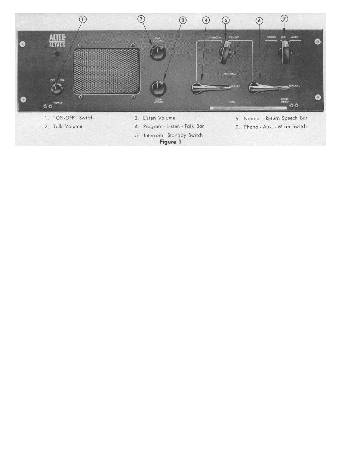
OPERATIONS AND USE OF CONTROLS
In order to utilize the 1556A ALTALK to its greatest
advantage, the function of each control should be
completely understood. Therefore, it is essential
that the instructions noted below are followed very
carefully. The controls for the operation of the
1556A ALTALK amplifier are identified numerically
in figure 1.
Phono and Aux: +/- 1 db 20c. to
10 kc
Microphone: — 3 db at 50c. and
15 kc
Controls: Intercom-Standby; Input Selector;
Program-Talk-Listen; NormalReturn Speech; Listen Volume;
Talk Volume; AC switch.
Power Supply: 117 volts, 50-60 cps, 65 watts
Tubes: 2 - 12AX7, 1 - 6DZ7, 1 - 6AX5
Dimensions: 51/4" H. 19" W. 61/2" D.
Color: Dar k Gre en
Weight: 13 lbs.
Accessories: Altec 1557A Speaker Selector
Switch Panel; 1558A Program
Selector Switch Panel; 13718
Call-in Switch Plate Assembly.
FUNCTIONS
The ON-OFF power switch,control 1,is located on the
front panel of the 1556A ALTALK unit. Power for the
ALTALK unit is obtained from any standard receptacle that supplies 105-125 volt, 50-60 cycles AC
current.
Separate volume controls for TALK and LISTEN,
controls 2 and 3 are located on the front panel of
the 1556A ALTALK unit (Figure 1). Each control is
operated individually in order to achieve the
desired level of listening and talking for all intercommunications (in and out).
INTERCOMMUNICATIONS
For "Master" to speaker area function set IntercomStandby switch in Intercom position; select area to
be called by setting proper selector switches on
1557A panel and press Program-Listen-Talk bar,
control 4. Adjust outgoing sound level with Talk
Volume, control 2. Release talk-listen bar to hear
reply.
Note: After completion of call return Intercom-
Standby switch to Standby position.
CALL-IN
For the "Master" to receive "call-in" from any
remote area the Intercom-Standby switch must be
in the Standby position and the Program-Listen-Talk
bar, control 4 in the Listen position.
Simplicity of operation is achieved in answering the
"call-in" by using the Normal-Return Speech bar,
control 6. Simply press talk bar to answer and
release to listen.
Page 2
Note: When this control is used the switch on
13718 Call-in unit must be held in "call"
position.
PRIVACY CIRCUIT
One of the outstanding features of the Altec 1556A
ALTALK unit is the incorporation of a Privacy Circuit. The use of the Privacy Circuit assures privacy
(freedom from supervisory monitoring) in all remote
areas. A more detailed description of this feature
can be found on Instruction Sheet No. 13765, of
13718 Call-in Switch Plate Assembly.
ALL CALL
This facility is not furnished as part of the 1556A
or 1557A units, however the I.C. - OFF - CHAN A
and CHAN B switch positions on the 1557A are
"bussed" and wired to the terminal panel for
connection of relay or manual switching facilities.
PROGRAM
Set Intercom-Standby switch control 5, to Standby
position; set Program-Listen-Talk bar, control 4 to
Program. Any radio program material (AUX) or
record player material (PHONO) will be heard thru
the Speaker-Microphone on the "Master". Establish
the sound level by adjusting Listen Volume, control 3.
Auxiliary and Phono input sources are connected to
pin jacks on the rear of the 1556A ALTALK unit,
and selection of desired input source is accomplished with Phono-Aux-Micro selector switch, control 7.
MICROPHONE
A high impedance microphone may be connected to
the phone jack at the rear of the 1556A "Master".
This microphone may be located remote from the
"Master" for program pickup. When using microphone in this manner control 7 must be in the
Micro position and the Program-Listen-Talk bar in
the Program position.
Note: When Phono-Aux-Micro inputs are in use
the "call-in" feature is inoperative. After
use, return control 4 to Listen position
and control 5 to Standby position.
PAGE 2
SINGLE AND DUAL CHANNEL
PROGRAM DISTRIBUTION
Program material may be distributed simultaneously
with intercommunication facilities by adding separate program amplifiers (Altec amplifiers such as
model 356A, 1568A, etc., are recommended). Block
diagrams, figures 2 and 3 show typical single and
dual channel systems.
In these systems program material is amplified
separately, permitting intercommunication service
thru the 1556A ALTALK to continue without program interruption.
WIRING
Connect 2 conductor #22 AWG or larger twisted
pair between terminals 3 and 4 on 1556A terminal
strip to "I.C." terminals on 1557A Speaker Selector
Switch Panel.
Connect loudspeakers and 13718 Call-In Switch
Plate Assembly to 1557A Speaker Selector Switch
Panel using 2 conductor #22 AWG or larger
twisted pair to numbered terminals. (In many installations shielded pair cable may not be required
for this circuit.)
Call-in and Privacy circuit must be 2 conductor
shielded #22 AWG or larger twisted pair. Connect
conductors to terminals 1 and 2 and shield to
terminal 8 on 1556A terminal strip.
Note: Installation may be simplified by loop-
ing "call-in" circuit wiring from one
speaker location to another.
MAINTENANCE
Since the Altec 1556A ALTALK Amplifier utilizes
high quality parts, that operate within their specified ratings, the need for routine maintenance is
minimized.
In the event that the 1556A ALTALK fails to operate
properly, all external wiring should be checked
immediately, as loose wiring or inadequate connections will result in noisy and intermittent operation. Be extremely careful that no exposed wires
come into contact with other wires, terminals, parts
of the chassis or any other metal surfaces.
Page 3

PARTS LIST
0.001 mfd ± 20% ,500 volt Disc.
.01 mfd GMV, Goodall Epoxy Disc.
15-30-20 mfd, 400-300-250 Mallory PFP
.047 mfd, 400 volt Micromold
Tropicap
40 mfd, 450 volt, Mallory FP146
50 mfd, 25 volt TC 29
47,000 ohm ± 10%, 1/2 watt
3.3 megohm ± 10%, 1/2 watt
330,000 ohm ± 10%, 1/2 watt
Potentiometer - Altec 12508
3,300 ohms ± 10%, 1/2 watt
1 meg ohms ± 10%, 1/2 watt
100,000 ohms ± 10%, 1/2 watt
270,000 ohms zb 10%, 1/2 watt
18,000 ohms ± 10%, 1/2 watt
Potentiometer - Altec 13614
500 ohm, 5 watt Axial Lead
3,900 ohms ±5%, 1 watt
C1
C2,3,10,11,12
C4A, 4B, 4C
C5, 6, 7
C8
C9
R1, 6, 8, 20
R2
R3, 4, 9
R5
R7
R10
R11, 12
R13, 14
R15
R16
R17
R18
R19
R21, 22
R23, 24, 25, 26
R27
S1
S2A, 2B, 2C
S3
S4
S5
SR-1
T1
T2
T3
VI, 2
V3
V4
1,200 ohm ± 10%, 1/2 watt
47 ohm ± 10%, 1 watt
1,000 ohm ± 10%, 1/2 watt
62,000 ohm ± 5 %, 1/2 watt
On-Off Switch - Altec 12536
Program - Listen - Talk Switch
Altec 13612
Phono - Auxiliary - Micro Switch
Altec 13610
Intercom - Standby Switch
Altec 13609
Normal - Return Speech Switch
Altec 13611
Rectifier - Selenium - Carl Holmes
S-3W5PL-HD7
Input Transformer - Altec 4782
Output Transformer - Altec 16612
Power Transformer - Altec 6302
12AX7 Vacuum Tube
6DZ7 Vacuum Tube
6AX5 Vacuum Tube
Page 4

 Loading...