

Altech UL508 Technical Data
32
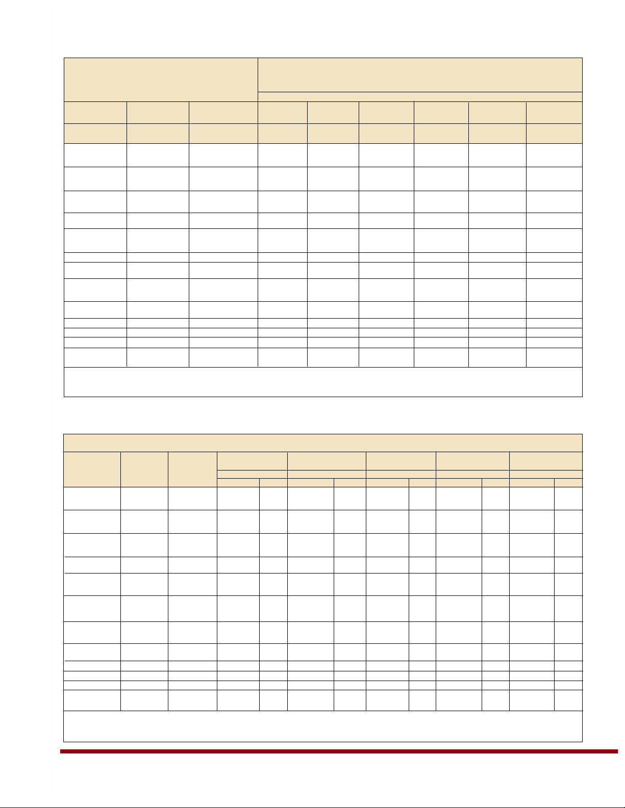
Altech UL508
FLA & LRC CONVERTED TO
TABLE HORSEPOWER (SEE NOTE #2)
USE FLA & LRC RATINGS WHERE
NO HP RATING IS GIVEN
NOMINAL CIRCUIT VOLTAGE
V-EA MOTOR MOTOR 110 -12 0 200 208 220-240 265 277
RATED NAMEPLATE NAMEPLATE VAC VAC VAC VAC VAC VAC
CURRENT FLA STARTING/
(SEE NOTE #1) RATING LRC RATING
0.30A 0.30A 1.80A
0.50A 0.50A 3.00A
0.75A 0.75A 4.35A
0.80A 0.80A 4.8A
1.0A 1.0A 6.0A
1.6A 1.6A 9.6A
2.0A 2.0A 12.0A
1/6hp 1/6hp 1/6hp
2.5A 2.5A 15.0A 1/6hp 1/6hp 1/6hp 1/6hp 1/4hp
3.0A 3.0A 18.0A 1/6hp 1/6hp 1/4hp 1/4hp 1/3hp
3.5A 3.5A 21.0A
1/4hp 1/4hp 1/4hp 1/3hp 1/3hp
4.0A 4.0A 24.0A
1/4hp 1/3hp 1/3hp 1/3hp 1/3hp
5.0A 5.0A 30.0A
1/6hp 1/3hp 1/2hp 1/2hp 1/2hp 1/2hp
6.0A 6.0A 36.0A
1/4hp 1/2hp 1/2hp 1/2hp 3/4hp 3/4hp
8.0A 8.0A 48.0A 1/3hp 3/4hp 3/4hp 1hp 1hp 1hp
10.0A 10.0A 60.0A
1/2hp 1hp 1hp 11/2hp 11/2hp 2hp
12.0A 12.0A 72.0A
1/2hp 11/2hp 11/2hp 2hp 2hp 2hp
12.5A 12.5A 75.0A 1/2hp 11/2hp 11/2hp 2hp 2hp 2hp
13.0A 13.0A 78.0A
1/2hp 11/2hp 11/2hp 2hp 2hp 2hp
15.0A 15.0A 90.0A 3/4hp 2hp 2hp 2hp 3hp 3hp
16.0A 16.0A 96.0A 1hp 2hp 2hp 2hp 3hp 3hp
20.0A 20.0A 120.0A 1
1/2hp 3hp 3hp 3hp 3hp 3hp
25.0A 25.0A 150.0A 2hp 3hp 3hp 3hp 5hp 5hp
30.0A 30.0A 180.0A 2hp 3hp 3hp 5hp 5hp 5hp
32.0A 32.0A 192.0A 2hp 3hp 5hp 5hp 5hp 5hp
40.0A 40.0A 240.0A 3hp 5hp 7
1/2hp 71/2hp 71/2hp 71/2hp
50.0A 50.0A 300.0A 3hp 71/2hp 10hp 10hp 10hp 10hp
60.0A 60.0A 360.0A 5hp 10hp 10hp 10hp 10hp 15hp
NOTE #1: For AC motor circuit nameplate full load current, AC general-use loads, AC resistance loads, AC incandescent lamp (tungsten) loads,
AC electric discharge lamp (ballast) loads.
NOTE #2: Conversions per UL508® Table 45.2 and NFPA-70: National Electrical Code® 2008 Tables 430-248 and 430-251(A).
FLA & LRC RATINGS CONVERTED TO TABLE HORSEPOWER (SEE NOTE #2)
USE FLA & LRC RATINGS WHERE NO HP IS LISTED
V-EA MOTOR MOTOR 11 0- 120 200 208 220-240 VAC 440-480
RATED NAMEPLATE NAMEPLATE VAC VAC VAC (SEE NOTE #3) VAC
CURRENT FLA STARTING/ Motor Design Motor Design Motor Design Motor Design Motor Design
(SEE NOTE #1) RATING LRC RATING B, C, D E B, C, D E B, C, D E B, C, D E B, C, D E
0.30A 0.30A 3.0A
0.50A 0.50A 5.0A
0.75A 0.75A 7.5A
0.80A 0.80A 8.0A
1.0A 1.0A 10.0A
1.6A 1.6A 16.0A
1/2hp 1/2hp
2.0A 2.0A 20.0A
1/2hp 1/2hp 3/4hp 3/4hp
2.5A 2.5A 25.0A 1/2hp 1/2hp 1/2hp 1/2hp 1/2hp 1/2hp 1hp 1hp
3.0A 3.0A 30.0A 1/2hp 1/2hp 1/2hp 1/2hp 1/2hp 1/2hp 11/2hp 11/2hp
3.5A 3.5A 35.0A
1/2hp 1/2hp 3/4hp 3/4hp 3/4hp 3/4hp 2hp 2hp
4.0A 4.0A 40.0A 3/4hp 3/4hp 3/4hp 3/4hp 3/4hp 3/4hp 2hp 2hp
5.0A 5.0A 42.0A
1/2hp 1/2hp 1hp 1hp 1hp 1hp 1hp 1hp 3hp 3hp
6.0A 6.0A 50.4A 1/2hp 1/2hp 1hp 1hp 1hp 1hp 11/2hp 11/2hp 3hp 3hp
8.0A 8.0A 67.2A 3/4hp 3/4hp 2hp 2hp 2hp 2hp 2hp 2hp 5hp 5hp
10.0A 10.0A 84.0A 1hp 1hp 2hp 2hp 2hp 2hp 3hp 3hp 5hp 5hp
12.0A 12.0A 100.8A 1
1/2hp 11/2hp 3hp 3hp 3hp 3hp 3hp 3hp 71/2hp 71/2hp
12.5A 12.5A 105.0A 11/2hp 11/2hp 3hp 3hp 3hp 3hp 3hp 3hp 71/2hp 71/2hp
13.0A 13.0A 109.2A 1
1/2hp 11/2hp 3hp 3hp 3hp 3hp 3hp 3hp 71/2hp 71/2hp
15.0A 15.0A 126.0A 2hp 2hp 3hp 3hp 3hp 3hp 3hp 3hp 10hp 10hp
16.0A 16.0A 134.4A 2hp 2hp 3hp 3hp 3hp 3hp 5hp 5hp 10hp 10hp
20.0A 20.0A 168.0A 3hp 3hp 5hp 5hp 5hp 5hp 5hp 5hp 10hp 10hp
25.0A 25.0A 210.0A 3hp 3hp 5hp 5hp 7
1/2hp 71/2hp 71/2hp 71/2hp 15hp 15hp
30.0A 30.0A 252.0A 5hp 5hp 5hp 5hp 7
1/2hp 71/2hp 10hp 10hp 20hp 20hp
32.0A 32.0A 268.8A 5hp 5hp 5hp 5hp 10hp 10hp 10hp 10hp 20hp 20hp
40.0A 40.0A 226.0A 5hp 5hp 10hp 7
1/2hp 10hp 71/2hp 10hp 10hp 30hp 20hp
50.0A 50.0A 282.5A 71/2hp 71/2hp 15hp 10hp 15hp 10hp 15hp 10hp 30hp 25hp
60.0A 60.0A 339.0A 10hp 10hp 15hp 10hp 20hp 10hp 20hp 15hp 40hp 30hp
NOTE #1: For AC motor circuit nameplate full load current, AC general-use loads, AC resistance loads, AC incandescent lamp (tungsten) loads,
AC electric discharge lamp (ballast) loads.
NOTE #2: Conversions
per UL508® proposed Tables 45.2 and 45.4 and NFPA-70: National Electrical Code® 2008 Tables 430-249, 430-250 and 430-251B).
Tabl e HP 2: AMPERE RATING & HORSEPOWER RATING 3 PHASE & 2 PHASE - 4 WIRE
Table HP 1: AMPERE RATINGS & HORSEPOWER RATING 1 PHASE

33
Altech UL508
Rated
Current B C D E G Z
(Amp) (Ohms) (Ohms) (Ohms) (Ohms) (Ohms) (Ohms)
0.3 — 16.8620 16.8620 14.52000 16.8620 31.5060
0.5 — 6.8540 6.0009 5.92000 6.8540 10.2460
0.75/0.8 — 3.0540 3.0540 2.70000 3.0540 5.3920
1.0 — 1.7000 1.7560 1.48000 1.7560 2.6910
1.6 — 0.5870 0.5870 0.57400 0.5870 0.9440
2.0 — 0.4190 0.4190 0.40500 0.4190 0.8900
2.5 — 0.2950 0.2950 0.26900 0.2950 0.4290
3.0 — 0.2020 0.2020 0.18600 0.2020 0.3460
3.5 — 0.1390 0.1390 0.13900 0.1390 0.1790
4.0 — 0.1090 0.1090 0.10600 0.1090 0.1620
5.0
— 0.0654 0.0654 0.05900 0.0654 0.1050
6.0 0.0528 0.0528 0.0491 0.04600 0.0491 0.0823
8.0 — 0.0278 0.0240 0.03040 0.0333 0.0371
10 0.0216 0.0216 0.0187 0.02020 0.0211 0.0278
12/12.5 — — — 0.00724 0.0084 0.0151
13 0.0113 0.0084 0.0085 0.00724 0.0084 0.0151
15/16 0.0085 0.0085 0.0076 0.00731
0.0076 0.0114
20 0.0067 0.0067 0.0064 0.00582 0.0064 0.0075
25 0.0050 0.0050 0.0041 0.00411 0.0046 0.0050
30/32 0.0032 0.0032 0.0027 0.00272 0.0030 0.0032
40 0.0025 0.0025 0.0022 0.00212 0.0022 0.0022
50 0.0019 0.0019 0.0018 0.00184 0.0019 0.00195
60/63 0.0018 0.0018 0.0017 0.00172 0.00179 —
Trip Characteristic
V-EA INTERNAL RESISTANCE
Resistances listed are “hot” values, as
opposed to cold start values. Operating
voltage drop across the V-EA and power
loss per pole can be approximated with
basic formulas:
V
DROP
= I
OPERATING
x R
TABLE
P
LOSS P/P
= I
2
OPERATING
x R
TABLE
Voltage drops should be reviewed when
V-EAs with high internal resistance are
used (e.g., load voltage minimums).
Power loss should be reviewed when
V-EAs with high rated currents are used
(e.g., enclosure heating).
The listed V-EA internal resistance
values should not be used in
calculations of available short-circuit
current downstream of the V-EA. The
dynamic impedance of the V-EA under
short-circuit conditions can vary
significantly from internal resistance
values in normal operation.
Frequency Effects on Magnetic Trip Curves
Trip Trip Zone Tri p Zone Tr ip Zon e Trip Zon e Trip Zon e
Curve At At At At At
16 2/3 - 60Hz 100 Hz 200 Hz 400 Hz DC
(x RC) (x RC) (x RC) (x RC) (x RC)
Z 2 - 3 2.2 - 3.3 2.4 - 3.6 2.8 - 4.2 3.0 - 4.5
B 3 - 5 3.3 - 5.5 3.6 - 6.0 4.2 - 7.0 4.5 - 7.5
C 5 - 10 5.5 - 11.0 6.0 - 12 7.0 - 14.0
7.5 - 15.0
G 8 - 10 8.8 - 11.0 9.6 - 12.0 11 .2 - 1 4.0 12.0 - 15.0
D 10 - 16 11. 0 - 17. 6 12.0 - 19.2 14.0 - 22.4 15.0 - 24.0
E 14 - 18 15.4 - 19.8 16.8 - 21.6 19.6 - 25.2 21.0 - 27.0
LINE CURRENT FREQUENCY EF FECTS ON TRIP CURVES
The thermal trip is not affected by the frequency of the line
current. The magnetic trip is within the trip zone of the
characteristic curve for frequencies from 16 2/3 to 60Hz. At
lower and higher frequencies, the magnetic trip will be
delayed longer than in di cat ed by the char ac ter is tic curve,
roughly as follows:
At 100Hz: Mag. Trip Current = 1.1 x curve current
At 200Hz: Mag. Trip Current = 1.2 x curve current
At 400Hz: Mag. Trip Current = 1.4 x curve current
At DC: Mag. Trip Current = 1.5 x curve current
For ex am ple, at 16 2/3 - 60 Hz the mag net ic trip zone for
the “G” char ac ter is tic is 8 to 10 times the rated current of
the specific V-EA (i.e., hold for at least 100ms at 8 x RC,
trip in less than 100ms at 10 x RC). With a 400Hz current,
a magnetic trip at 10 x RC would be greatly delayed
(thermal would likely trip first), as the magnetic trip zone is
now 11.2 to 14 x RC. If a quicker magnetic trip is required
with 400Hz, the “B” or “C” characteristic should be
considered.
MECHANICAL ENDURANCE RATINGS (ON/OFF OPERATIONS)
Application 2 x (1.15 x RC) 2 x RC RC No Load Tota l
AC General Use — 6000 — 4000 10000
AC Motor Starting Across the Line 1000 — 5000 4000 10000
AC Incandescent Lamps (Tungsten) — — 6000 4000 10000
AC Electrical Discharge Lamps (Ballast) — 6000 — 4000 10000
AC Resistance — 6000 — 4000 10000
Manufacturers self certification 20000 ON/OFF operations with no load
 Loading...