

Page 1
Altech UL1077
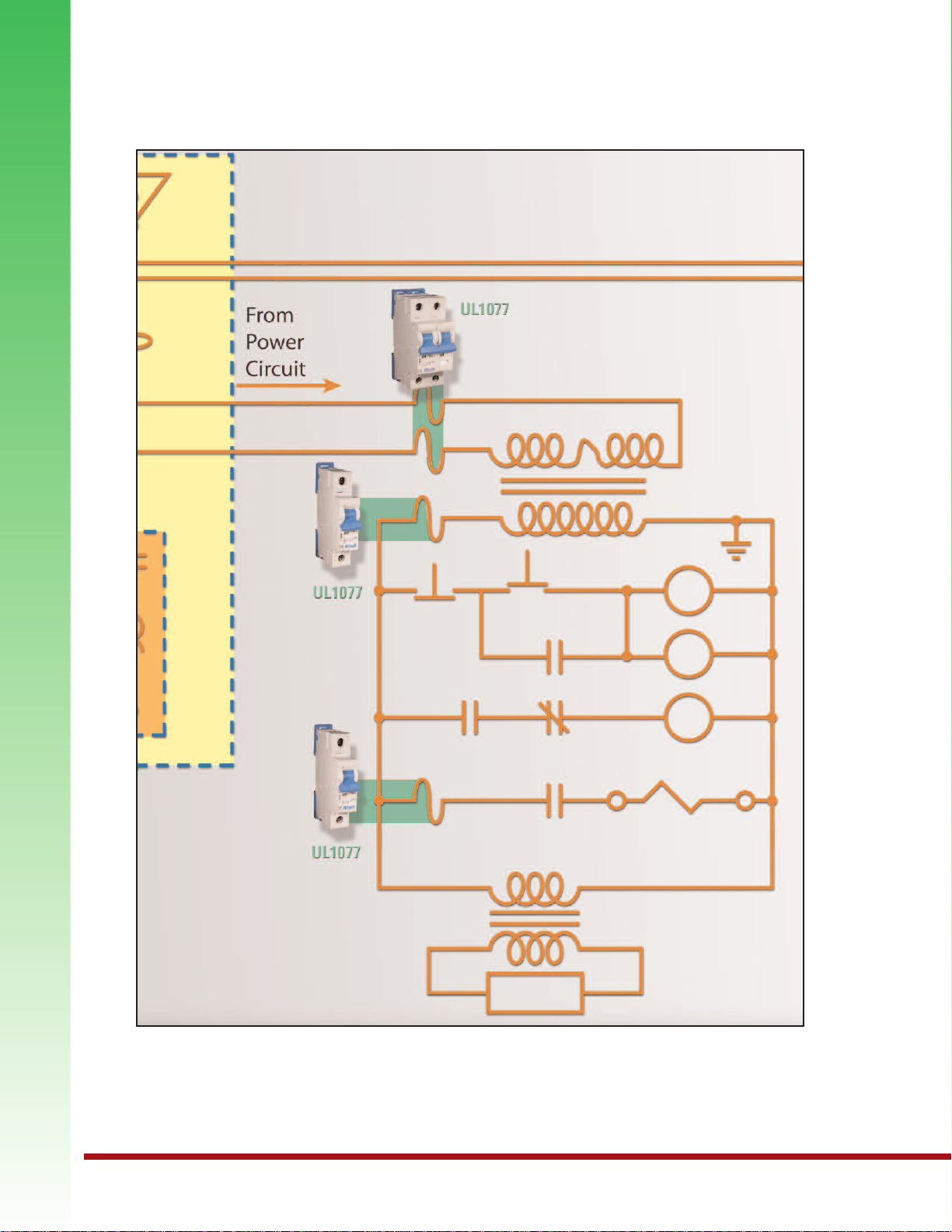
Typical UL1077 Application
Control Circuit of a UL508A Panel
Disclaimer: This is just an example application. Installation should be done by a qualified
electrician under the guidance of UL/NEC®specifications..
8 9
Page 2
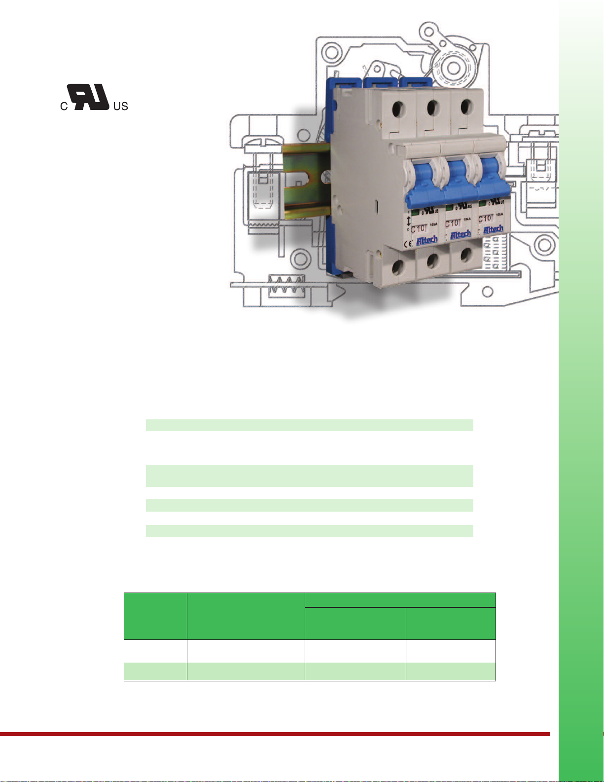
R-Series
E301611
UL1077 Recognized
Supplementary
Protector
• DIN Rail Mounted
• 17.5mm width per pole
• Thermal Magnetic
• 480Y/277V AC, 50/60Hz
• 10kA Short Circuit
Withstand Capacity 10kA
• Positive Trip indicator
(Green - off/tripped, Red - on)
• Applications (on the load side
of Branch Circuit Protection)
include: Sensitive Electronics,
Power Supplies, Appliance
circuits, etc.
Voltage Rating
Short Circuit Withstand Rating
(UL - Ratings)
Interrupting Capacity
(IEC/EN60898/60947-2)
Calibration Temperature
Terminal Size Acceptability - min/max
Terminal Torque - min/max
Terminal Protection Degree
SHORT CIRCUIT WITHSTAND RATINGS FOR R-SERIES SUPPLEMENTARY PROTECTOR
Trip Amp UL-Listed No Backup Fuse
Curve Range Class J Fuse Required
All 0.5 - 6A 4xRC* 10kA
All
*up to nearest rated current
8 - 63A 4xRC* 5kA
480Y/277VAC
0.5-6A (RC): 10kA with no back-up fuse
8-63A (RC):
Class J bac
0.5-63A (RC): 10kA
30°C (86°F)
2.5 mm
1.5 Nm (13 lb. in.) / 2 Nm (17.5 lb . in.)
IP20
10kA with UL-listed
k-up fuse; 5kA with no back-up fuse
2
(12 AWG) / 25mm2(3 AWG)
Backup Protection
up to 10kA up to:
DC voltage rating: 48 VDC (self-certified).
Altech UL1077
9
Page 3
Altech UL1077
17.5 (0.69 in.) 35 (1.38 in.) 52.5 (2.07 in.)
44 (1.73 in.)
45 (1.77 in.)
6.5 (0.26 in.)
60 (2.36 in.)
77 (3.03 in.)
96.1 (3.80 in.)
85.5 (3.37 in.)
2
10
-3
4x10
-3
4x10
-2
10
-1
0.4
1
4
10
1
4
10
40
60
10
-2
3 4 6 8 101620
Multiple of Rated Current
Seconds Time t Minutes
BB CC DDBCD
Warning!
This information should only be used as a selection guide. The use of a Miniature Circuit Breaker/Supplementary Protector
in an application with a certain Trip-Characteristic always requires prototype testing! It is the responsibility of the circuit
design engineer to select the appropriate Miniature Circuit Breaker/Supplementary Protector for his specific application.
*The value of each characteristic is shown vertically beneath its corresponding heading.
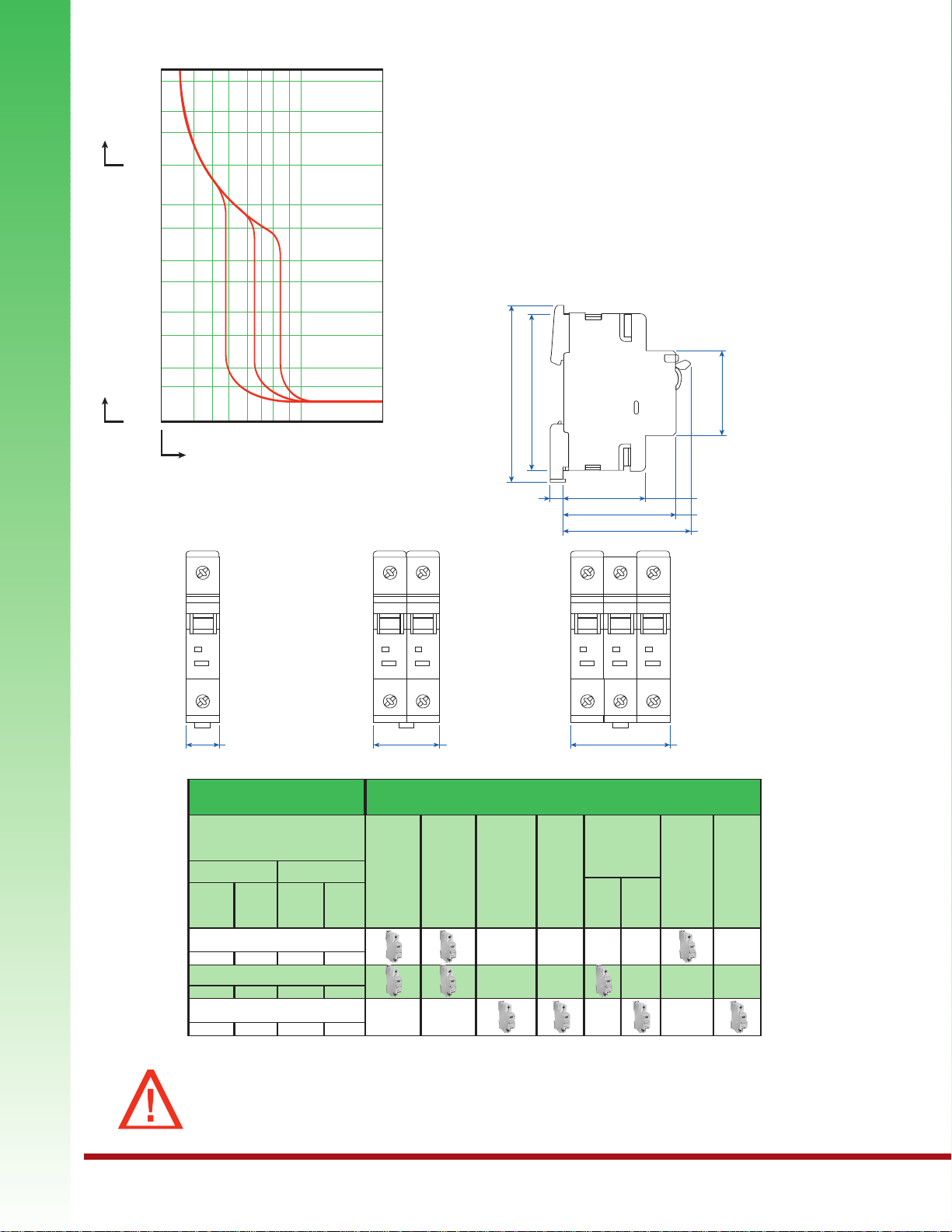
Characteristic TripBoundaries
Trip-Characteristics* Applications
B-Characteristics
C-Characteristics
D-Characteristics
Thermal Trip
Lighting
Control
Circuits
Wiring
Protection
Business
Equipment
Appliances
Transformers
Power
Supplies
Heaters
Must not
Trip>100ms
1.13xRC 1.45xRC 3xRC 5xRC
1.13xRC 1.45xRC 5xRC 10xRC
1.13xRC 1.45xRC 10xRC 20xRC
Must Trip
<1hr
Must not
Trip>100ms
Must Trip
at 100ms
Magnetic Trip
Low
Inrush
High
Inrush
Motors
General
Electronics
Reactive
Load
1 POLE 2 POLE 3 POLE
Time
versus
Current Trip Curve
For the exact trip curve,
please refer to page 21.
Dimensions in mm
side view
10
11
Page 4

B-Trip
Characteristic
E301611
Application Examples:
Business equipment, wiring protection,
lighting, appliances, control circuits and
some electronic applications. Relatively
long thermal trip delay but low magnetic
trip point.
One Pole
Three Pole
Rated Type/
Current Cat. No.
0.5A 1BU05R
1.0A 1BU1R
2.0A 1BU2R
3.0A 1BU3R
4.0A 1BU4R
5.0A 1BU5R
6.0A 1BU6R
8.0A 1BU8R
10A 1BU10R
12A 1BU12R
13A 1BU13R
15A 1BU15R
16A 1BU16R
20A 1BU20R
25A 1BU25R
30A 1BU30R
32A 1BU32R
40A 1BU40R
50A 1BU50R
60A 1BU60R
63A 1BU63R
Standard Pack: 12
Weight:
0.5A - 63A: 1.6kg (3.54 lb.)
Rated Type/
Current Cat. No.
0.5A 3BU05R
1.0A 3BU1R
2.0A 3BU2R
3.0A 3BU3R
4.0A 3BU4R
5.0A 3BU5R
6.0A 3BU6R
8.0A 3BU8R
10A 3BU10R
12A 3BU12R
13A 3BU13R
15A 3BU15R
16A 3BU16R
20A 3BU20R
25A 3BU25R
30A 3BU30R
32A 3BU32R
40A 3BU40R
50A 3BU50R
60A 3BU60R
63A 3BU63R
Standard Pack: 4
Weight:
0.5A - 63A: 1.66kg (3.67 lb.)
Two Pole
Accessories
see page 19
Rated Type/
Current Cat. No.
0.5A 2BU05R
1.0A 2BU1R
2.0A 2BU2R
3.0A 2BU3R
4.0A 2BU4R
5.0A 2BU5R
6.0A 2BU6R
8.0A 2BU8R
10A 2BU10R
12A 2BU12R
13A 2BU13R
15A 2BU15R
16A 2BU16R
20A 2BU20R
25A 2BU25R
30A 2BU30R
32A 2BU32R
40A 2BU40R
50A 2BU50R
60A 2BU60R
63A 2BU63R
d Pack: 6
Standar
Weight:
0.5A - 63A: 1.6kg (3.54 lb.)
Description Type/
Neutral Pole ALTN2
Shunt Trip (AC, DC) FA_ _ _ACR
Undervoltage Trip (AC, DC) UV_ _ _ACR
Auxiliary/Signal Contact HSTCOR
Auxiliary Contact H1COR
Lock-out Adapter EASS2
***
Insert coil voltage.
Cat. No.
***
FA_ _ _DCR
***
***
UV_ _ _DCR
***
H2COR
Four Pole
Please contact
Altech.
Non-standard current ratings available. Minimum quantities may apply. Please contact Altech for further details.
Altech UL1077
11
Page 5

C-Trip
Characteristic
E301611
Application Examples:
Lighting, wiring protection, appliances,
business equipment, and control circuit
applications. Relatively long thermal trip
delay and medium magnetic trip point.
Altech UL1077
One Pole
Standard Pack: 12
Weight:
0.5A - 63A: 1.6kg (3.54 lb.)
Three Pole
Standard Pack: 4
Weight:
0.5A - 63A: 1.66kg (3.67 lb.)
Rated Type/
Current Cat. No.
0.5A 1CU05R
1.0A 1CU1R
2.0A 1CU2R
3.0A 1CU3R
4.0A 1CU4R
5.0A 1CU5R
6.0A 1CU6R
8.0A 1CU8R
10A 1CU10R
12A 1CU12R
13A 1CU13R
15A 1CU15R
16A 1CU16R
20A 1CU20R
25A 1CU25R
30A 1CU30R
32A 1CU32R
40A 1CU40R
50A 1CU50R
60A 1CU60R
63A 1CU63R
Rated Type/
Current Cat. No.
0.5A 3CU05R
1.0A 3CU1R
2.0A 3CU2R
3.0A 3CU3R
4.0A 3CU4R
5.0A 3CU5R
6.0A 3CU6R
8.0A 3CU8R
10A 3CU10R
12A 3CU12R
13A 3CU13R
15A 3CU15R
16A 3CU16R
20A 3CU20R
25A 3CU25R
30A 3CU30R
32A 3CU32R
40A 3CU40R
50A 3CU50R
60A 3CU60R
63A 3CU63R
Two Pole
Accessories
see page 19
Rated Type/
Current Cat. No.
0.5A 2CU05R
1.0A 2CU1R
2.0A 2CU2R
3.0A 2CU3R
4.0A 2CU4R
5.0A 2CU5R
6.0A 2CU6R
8.0A 2CU8R
10A 2CU10R
12A 2CU12R
13A 2CU13R
15A 2CU15R
16A 2CU16R
20A 2CU20R
25A 2CU25R
30A 2CU30R
32A 2CU32R
40A 2CU40R
50A 2CU50R
60A 2CU60R
63A 2CU63R
Standard Pack: 6
Weight:
0.5A - 63A: 1.6kg (3.54 lb.)
Description Type/
Neutral Pole ALTN2
Shunt Trip (AC, DC) FA_ _ _ACR
Undervoltage Trip (AC, DC) UV_ _ _ACR
Auxiliary/Signal Contact HSTCOR
Auxiliary Contact H1COR
Lock-out Adapter EASS2
***
Insert coil voltage.
Cat. No.
***
FA_ _ _DCR
***
***
UV_ _ _DCR
***
H2COR
Four Pole
Please contact
Altech.
12
Non-standard current ratings available. Minimum quantities may apply. Please contact Altech for further details.
Page 6

D-Trip
Characteristic
E301611
Application Examples:
Transformers, power supplies and
reactive loads. Relatively long thermal trip
delay and very high magnetic trip point.
One Pole
Three Pole
Rated Type/
Current Cat. No.
0.5A 1DU05R
1.0A 1DU1R
2.0A 1DU2R
3.0A 1DU3R
4.0A 1DU4R
5.0A 1DU5R
6.0A 1DU6R
8.0A 1DU8R
10A 1DU10R
12A 1DU12R
13A 1DU13R
15A 1DU15R
16A 1DU16R
20A 1DU20R
25A 1DU25R
30A 1DU30R
32A 1DU32R
40A 1DU40R
50A 1DU50R
60A 1DU60R
63A 1DU63R
Standard Pack: 12
Weight:
0.5A - 63A: 1.6kg (3.54 lb.)
Rated Type/
Current Cat. No.
0.5A 3DU05R
1.0A 3DU1R
2.0A 3DU2R
3.0A 3DU3R
4.0A 3DU4R
5.0A 3DU5R
6.0A 3DU6R
8.0A 3DU8R
10A 3DU10R
12A 3DU12R
13A 3DU13R
15A 3DU15R
16A 3DU16R
20A 3DU20R
25A 3DU25R
30A 3DU30R
32A 3DU32R
40A 3DU40R
50A 3DU50R
60A 3DU60R
63A 3DU63R
Standard Pack: 4
Weight:
0.5A - 63A: 1.66kg (3.67 lb.)
Two Pole
Accessories
see page 19
Rated Type/
Current Cat. No.
0.5A 2DU05R
1.0A 2DU1R
2.0A 2DU2R
3.0A 2DU3R
4.0A 2DU4R
5.0A 2DU5R
6.0A 2DU6R
8.0A 2DU8R
10A 2DU10R
12A 2DU12R
13A 2DU13R
15A 2DU15R
16A 2DU16R
20A 2DU20R
25A 2DU25R
30A 2DU30R
32A 2DU32R
40A 2DU40R
50A 2DU50R
60A 2DU60R
63A 2DU63R
Standard Pack: 6
Weight:
0.5A - 63A: 1.6kg (3.54 lb.)
Description Type/
Neutral Pole ALTN2
Shunt Trip (AC, DC) FA_ _ _ACR
Undervoltage Trip (AC, DC) UV_ _ _ACR
Auxiliary/Signal Contact HSTCOR
Auxiliary Contact H1COR
Lock-out Adapter EASS2
***
Insert coil voltage.
Cat. No.
***
FA_ _ _DCR
***
***
UV_ _ _DCR
***
H2COR
Four Pole
Please contact
Altech.
Non-standard current ratings available. Minimum quantities may apply. Please contact Altech for further details.
Altech UL1077
13
Page 7

1
1.13 1.45
0.01
0.05
0.1
0.5
1
5
10
20
40
1
2
4
6
8
20
10
40
60
120
2016141210987652 34
B, C and D Trip
Less than 10A
1
1.13 1.45
0.01
0.05
0.1
0.5
1
5
10
20
40
60
120
240
360
480
1200
600
2400
3600
7200
2016141210987652 34
B, C and D Trip
10A and higher
Multiple of Rated Current
Multiple of Rated Current
Seconds Minutes
Tri pping time t
Seconds Minutes
Tri pping time t
BC D
BC D
Rated
current
of MCB
Internal Impedances & Power Loss MCB Temperature Compensation
Internal
impedance
Power
loss on
CB
Maximum allowable
impedance of
breakdown loop (0.2/0.4s)
Effective rated current allowing for ambient temperature.
In(A)
Z (mΩ)
P (W)
Z
s
(Ω)
I cor (A)
Char.
B,C,D
Char.
B,C,D
Char.B Char.C Char.D
Ambient Temperature
-20°C -10°C 0°C 10°C 20°C 30°C 40°C 50°C 60°C
0.50 6600 1.7 42.0 51.1 28.8 0.61 0.59 0.57 0.55 0.53 0.50 0.47 0.44 0.42
1.00 1650 1.7 46.0 25.6 14.4 1.21 1.18 1.14 1.10 1.05 1.00 0.93 0.88 0.83
2.00 370 1.5 23.0 12.8 7.2 2.42 2.36 2.28 2.20 2.10 2.00 1.86 1.76 1.67
3.00 210 1.9 15.3 8.5 4.8 3.63 3.54 3.42 3.30 3.15 3.00 2.79 2.64 2.50
4.00 126 2.0 11.5 6.4 3.6 4.84 4.72 4.56 4.40 4.20 4.00 3.72 3.52 3.33
6.00 51 1.8 7.7 4.3 2.4 7.30 7.10 6.80 6.60 6.30 6.00 5.60 5.30 5.00
8.00 21 1.3 5.8 3.2 1.8 9.70 9.40 9.10 8.80 8.40 8.00 7.40 7.00 6.70
10.00 14.8 1.5 4.6 2.6 1.4 12.1 11.8 11.40 11.00 10.50 10.00 9.30 8.80 8.30
13.00 11.3 1.9 3.5 2.0 1.1 15.7 15.3 14.80 14.30 13.70 13.00 12.10 11.50 10.80
16.00 7.5 1.9 2.9 1.6 0.9 19.4 18.9 18.20 17.60 16.80 16.00 14.90 14.10 13.30
20.00 6.3 2.5 2.3 1.3 0.7 24.2 23.60 22.80 22.00 21.00 20.00 18.60 17.60 16.70
25.00 4.4 2.8 1.8 1.0 0.6 30.3 29.50 28.50 27.50 26.30 25.00 23.30 22.00 20.80
32.00 3.1 3.2 1.4 0.8 0.4 38.7 37.80 36.50 35.20 33.60 32.00 29.80 28.20 26.70
40.00 2.5 4.0 1.2 0.6 0.4 48.4 47.20 45.60 44.00 42.00 40.00 37.20 35.20 33.30
50.00 2.2 5.5 0.9 0.5 0.3 60.5 59.0 57.00 55.00 52.50 50.00 46.50 44.10 41.70
63.00 1.6 6.4 0.7 0.4 0.2 76.2 74.30 71.80 69.30 66.20 63.00 58.60 55.50 52.50
R-Series Trip Curves
Altech UL1077
Temperature and Power Loss Specifications
14
Page 8

Accessories
R-Series
Supplementary
Protector
E301611
Shunt Trip
Undervoltage Trip
Accessories can be factory or field mounted on R-Ser ies supplementary protectors for enhanced
control and monitoring capabilities. Field mounting kits include all necessary parts and instructions.
Accessories can be gang mounted on a single controller (the A uxiliary Switch in the outside
position). The mounting arr angement links the inter nal latch-pins f or the tr ipping mechanisms ,
ensuring simultaneous trips. Handles are linked to simplify manual resetting.
Neutral
Pole
Description Type/ Cable Cable Torque Torque
Neutral ALTN2 25mm
Standard Pack: 10
Weight: 1.25kg (2.77 lb.)
(63A/480Y/277 VAC)
Cat. No. Max Min Max Min
2
AWG 3 AWG 12 17.5 lb-in 12 lb-in
2.5mm
2
2Nm 1.5Nm
Shunt Trip
and Undervoltage Trip
Description Shunt Trip Undervoltage Trip Cable Cable Torque Torque
AC Coil:
12V AC FA12ACR UV12ACR
24V AC FA24ACR UV24ACR
48V AC FA48ACR UV48ACR
60V AC FA60ACR UV60ACR
110V AC FA110ACR UV110ACR
120V AC FA120ACR UV120ACR
230V AC FA230ACR UV230ACR
277V AC FA277ACR UV277ACR
400V AC FA400ACR UV400ACR
DC Coil:
12V DC FA12DCR UV12DCR
24V DC FA24DCR UV24DCR
48V DC FA48DCR UV48DCR
110V DC FA110DCR UV110DCR
Standard Pack: 10
Weight: 1.1kg (2.43 lb.)
Type/Cat. No. Type/Cat. No. Max Min Max Min
2.5mm
2
2Nm 1.5Nm
2
2Nm 1.5Nm
25mm22.5mm
3 AWG 12 AWG 17.5 lb-in 12 lb-in
2
25mm
3 AWG 12 AWG 17.5 lb-in 12 lb-in
Auxiliary
Contact
Description Type/ Cable Cable Torque Torque
1 x CO H1COR
2 x CO H2COR
1 x CO, 1 Signal HSTCOR
& Test Button
Standard Pack: 15
Weight: H1COR: 0.5kg (1.32 lb.); H2COR, HSTCOR: 0.72kg (1.59 lb.)
(4A/230 VAC)
Cat. No. Max Min Max Min
2
2.5mm
AWG 12 AWG 20 4 lb-in 3 lb-in
0.5mm
2
0.5Nm 0.33Nm
Lock-out
Adaptor
Description Type/ Lock
Yellow EASS2 small suitcase lock
Standard Pack: 10
Weight: 50g (1.76 oz.)
Cat. No. to use
Altech UL1077
15
 Loading...