

Page 1
1352 46
1322 13
Pin
Phase
Phase 1 Phase 2
Phase 3
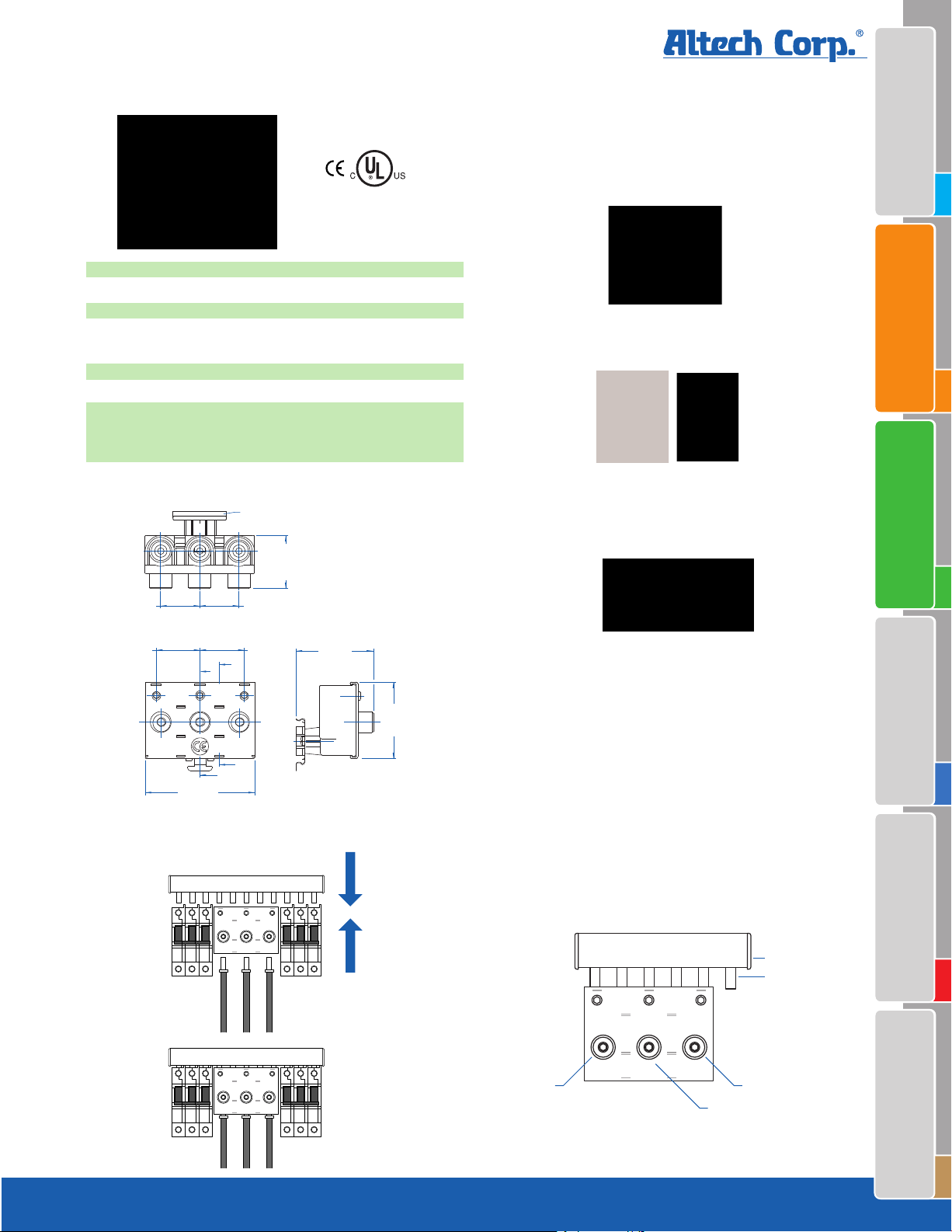
Power Feed Block
A
A
B
B
43.5 mm
(1.71 in.)
35.6 mm
(1.40 in.)
35.6 mm
(1.40 in.)
31.6 mm
(1.24 in.)
31.6 mm
(1.24 in.)
DIN Rail Clip
88.5 mm
(3.48 in.)
63 mm
(2.48 in.)
63 mm
(2.48 in.)
Miscellaneous Accessories
UL 489ANNEX UL 508UL 1077
UL508 listed
E205412
Type/Cat. No. P95UB
Electrical Ratings 200A/ 480VAC
Terminal Site Acceptability 1-4/0 AWG (50-120mm
Recommended/ 19.5Nm (175lb. in.)
Required Torque
Material of Lug/ Terminal Brass
Insulation Material Polyamide
For use with UL1077/508 18 and 25mm
3 phase busbars
(standard spacing only)
Dimensions
End Caps
2
)
Type/Cat. No: 18/25CAP1P
For use with: 18/25mm
2
Type/Cat. No: 18/25CAP3P
For use with: 18/25mm
2
1 phase Busbar
2
2&3 phase Busbar
Insulation Caps
Assembly Instructions
Type/Cat. No: BRB5W (5 per strip)
For use with: 18/25mm
2
1-3 phase Busbar
NOTE: The Power Feed Block uses the space of 5 Pins
of the standard spacing Busbar (see drawing below).
Phase 1 connects to Pin 1, Phase 2 to Pin 3 and Phase
3 to Pin 5. Pin 2 and 4 are not in use. Pin 6 should be
covered with an insulation cap if phase sequence stays
the same. Therefore, the Power Feed Block covers 6 pins
to connect to the three phases.
UL 1077
Equipment Breakers
Circuit Breakers
Earth Leakage
 Loading...