

Page 1
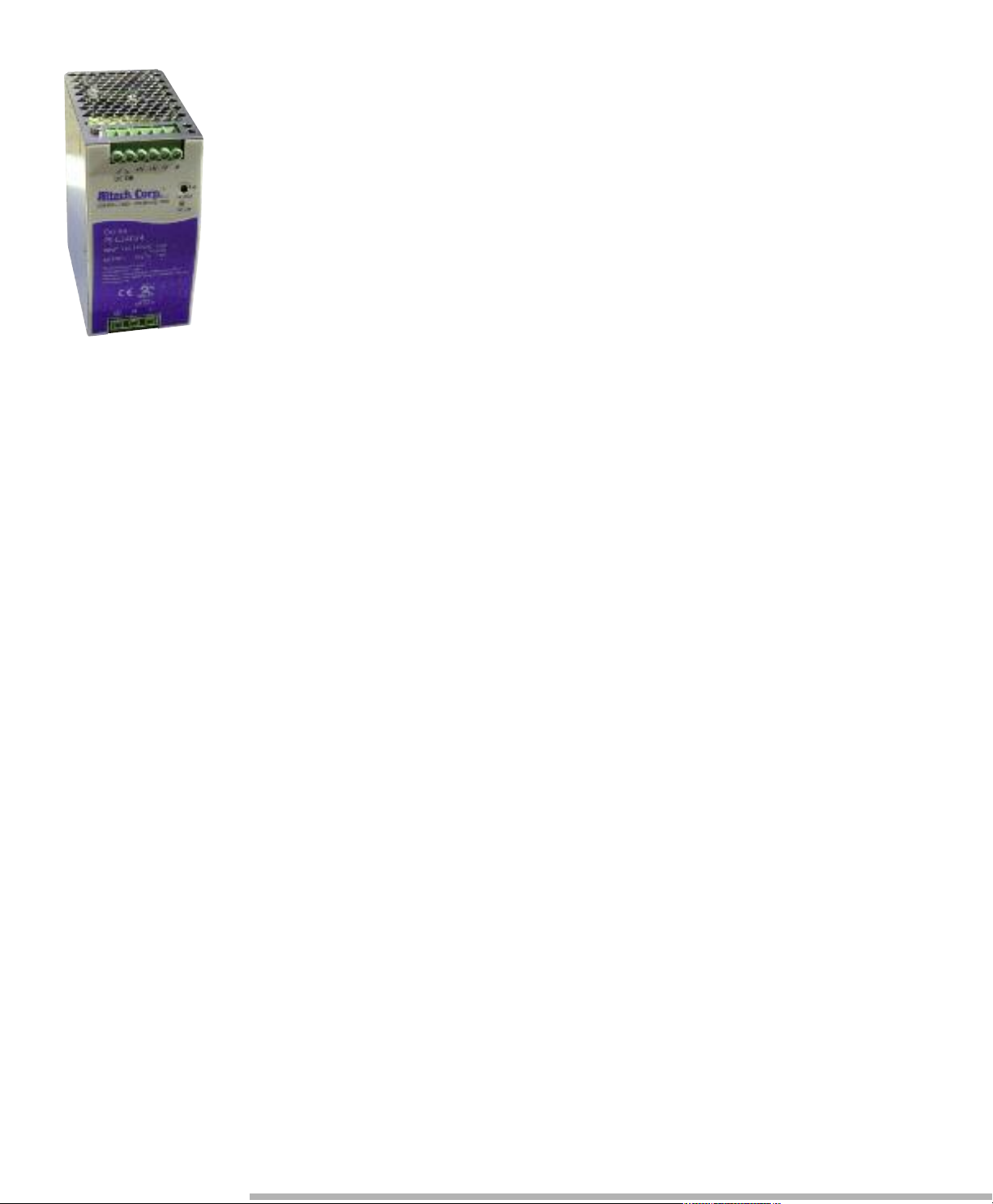
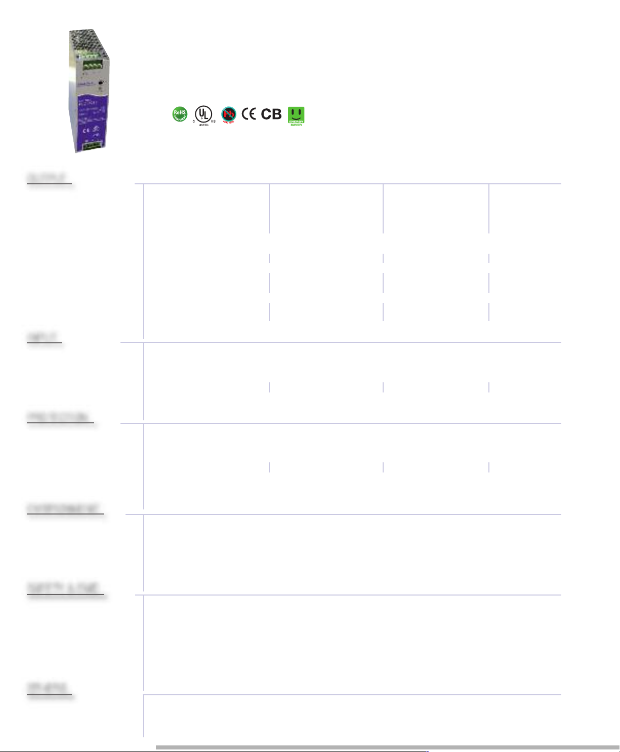
High Efficiency Compact Housing
Power Supply
This high performance single output compact DIN rail PS-C Series, with up-to-date
circuit design, possess up to 94% of high efficiency and works within 110 ~150% rated
output power for up to 3 seconds.
With built-in active PFC function, PS-C Series is a full range AC input switching power
supply that fulfills the requirement of EN61000-3-2 for harmonic current. The compact
design helps save the precious space on the rail and also makes it up to 50% smaller in
size compare to its predecessor model PS-Series. Meanwhile, PS-C also have 5~9%
higher efficiency than corresponding models of the PS-Series, which response to the
trend of green power with energy saving concept.
Other standard functions include DC OK relay contact, on panel LED indicator, and
protection for short-circuit, overload (constant current limiting, shut down if over 3
seconds), over voltage, and over temperature. To fulfill the requirements of marine and
semi-conductor related usage, PS-C Series also complies with GL and SEMI F47 norms
in addition to UL, CUL and CE certificates. Suitable applications are factory automation,
semi-conductor fabrication equipment, marine related installation, and electromechanical applications.
• Input voltage range: 88-264V AC; 124-370V DC
• AC inrush current (typical):Cold start: 65A at 230V AC (PSC-240)
• DC adjustment range (typical): 12V: 12-14V, 24V: 24-28V, 48V: 48-55V,
• Overload protection (typical): 110%-150% rated output power
• Overvoltage protection (typical): 14-17V for 12V model (PSW-120),
29-33V for 24V model
56-65V for 48V model
• Over temperature protection: 95˚C ± 5˚C (PSC-120/240); 105˚C ± 5˚C
• Withstand voltage: I/P-O/P:3KV AC, I/P-FG:1.5KV AC, O/P-FG:0.5KV AC,
• Working temperature: -25 to +70°C (-4° to +158°F),
refer to output derating curve
• Safety standards: UL508; EN60950-1 compliant
• EMC standards: Compliance to EN55022 class B,
EN61000-4-2,3,4,5,6,8,11, ENV50204,
EN61000-6-2, EN61204-3, heavy Industry level,
SEMI F47, GL
• Military standard: MIL-HDBK-217K
Page 2
PS-C Series
Features:
• High efficiency up to 94% and low power dissipation
• Universal AC Input / Full Range
• 150% peak load capability
• Built-in active PFC function, PF>0.93
• Protections: Short circuit / Overload / Overvoltage / Over temperature
• Cooling by free air convection
• Din rail mountable
• LED indicator for power on
• UL 508 (industrial control equipment) approved
• EN61000-6-2(EN50082-2) industrial immunity level
• 100% full load burn-in test
• Built-in DC OK relay contact
• 3 year warranty
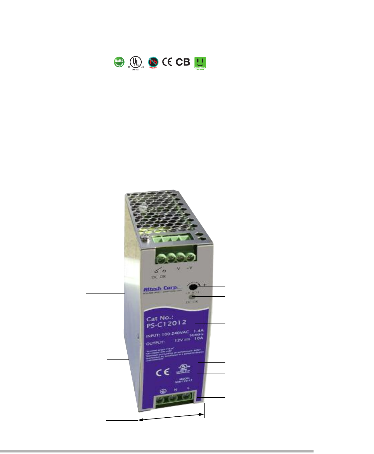
35mm DIN Rail
Mounting
Rugged metal housing
Narrow for maximized
panel space
Adjustable DC Output Voltage
DC on LED signal
Easy to understand
layout panel
CE Compliance
UL508 Compliance
Universal Input
Page 3
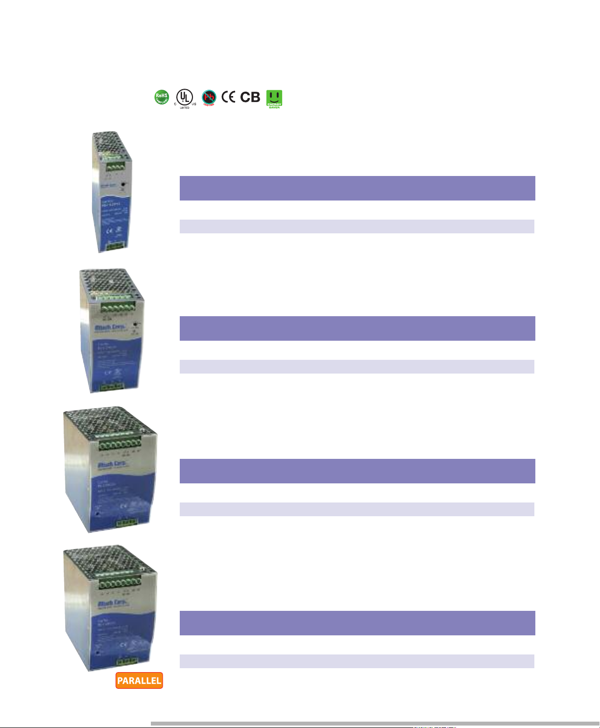
120-480W Single Phase
COMPACT SIZE POWER SUPPLIES
120W Single Output DIN Rail Power Supply
at. No. Output Tol. Ripple & Efficiency NOTES
C
V DC A % Noise
PS-C12012 12V DC 10A ±1% 100 mVp-p 89%
PS-C12024 24V DC 5A ±1% 100 mVp-p 91%
PS-C12048 48V DC 2.5A ±1% 120 mVp-p 91%
240W Single Output DIN Rail Power Supply
Cat. No. Output Tol. Ripple & Efficiency NOTES
V DC A % Noise
PS-C24024 24V DC 10A ±1% 100 mVp-p 94%
PS-C24048 48V DC 5A ±1% 120 mVp-p 94%
480W Single Output DIN Rail Power Supply
Cat. No. Output Tol. Ripple & Efficiency NOTES
V DC A % Noise
PS-C48024 24V DC 20A ±1% 100 mVp-p 94%
PS-C48048 48V DC 10A ±1% 120 mVp-p 94%
480W Single Output DIN Rail Power Supply
with PFC and Parallel Function (1+7)
Cat. No. Output Tol. Ripple & Efficiency NOTES
V DC A % Noise
PS-C480P24 24V DC 20A ±1% 100 mVp-p 94%
PS-C480P48 48V DC 10A ±1% 120 mVp-p 94%
Page 4
SPECIFICATIONS
1
1
3
.
5
4
0
1
2
5
.
2
1
1
3
.
5
6
3
1
2
5
.
2
1
2
8
.
5
8
5
.
5
12
5
.
2
Pin No.
Pin No.
1
1,2
2
3
3
Assi gnment
Assignment
FG
AC/L
AC/N
Relay Contact
DC OUTPUT -V
4
D
C OUTPUT +V
Terminal Pin. No Assign. (
TB1)
Terminal Pin. No Assign.
(
TB2)
Pin No.
P
in No.
1
1,2
2
3,4
3
Assi gnment
A
ssignment
FG
AC/L
AC/N
Relay Contact
DC OUTPUT -V
5,6
DC OUTPUT +V
Terminal Pin. No Assign. (TB1)
Terminal Pin. No Assign.
(TB2)
Pin No.
Pin No.
1
1,2
2
3,4
3
Assi gnment
Assignment
FG
AC/L
AC/N
DC OUTPUT +V
DC OUTPUT -V
5,6
Relay Contact
7,8
NC
Terminal Pin. No Assign. (TB1)
Terminal Pin. No Assign.
(TB2)
Pin No.
1,2
3,4
Assignment
DC OUTPUT +V
DC OUTPUT -V
5,6
Relay Contact
7
P+ (current share)*
8
P- (current share)*
* Only parallel function.
Terminal Pin. No Assign. (TB2)
For Parallel ModelFor Parallel Model
Pin No.
1
2
3
Assi gnment
FG
AC/L
AC/N
Terminal Pin. No Assign. (TB1)
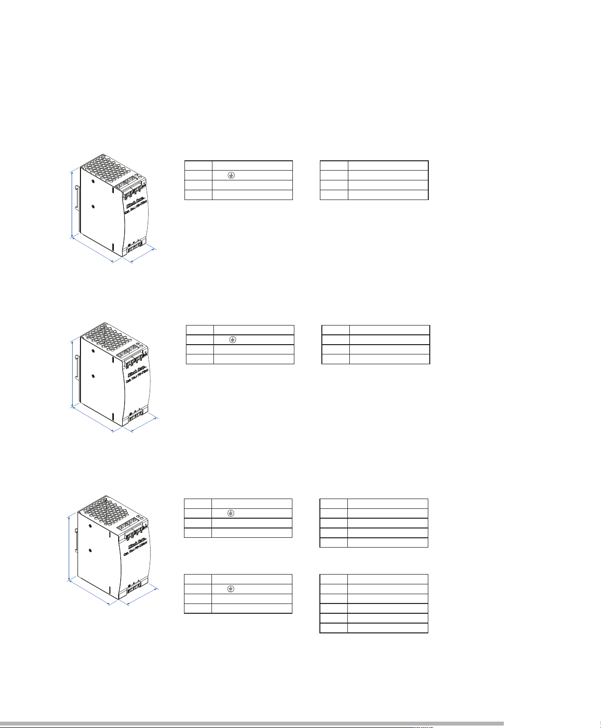
PS-C120 Series
PS-C240 Series
Universal Input: 88-264V AC, 124-370V DC full range,
1.4A/115V AC, 0.7A/230V AC
Connection: Input - 3 poles, Output – 4 poles screw terminal
Size (WxHxD): 40x125.2x113.5mm (1.57x4.93x4.47 inches)
Packaging: 1/box; 1.48lbs / 0.67Kg
PS-C480 Series
Switch select Input: 88-264V AC, 124-370V DC range,
2.6A/115V AC, 1.3A/230V AC
Connection: Input - 3 poles, Output – 6 poles screw terminal
Size (WxHxD): 63x125.2x113.5mm (2.48x4.93x4.47 inches)
Packaging: 1/box; 2.27lbs / 1.03Kg
Universal Input: 90-264V AC, 127-370V DC full range,
5A/115V AC, 2.5A/230V AC
Connection: Input - 3 poles, Output – 12 poles screw terminal
Size (WxHxD): 85.5x125.2x128.5mm (3.37x4.93x5.06 inches)
Packaging: 1/box; 3.53lbs / 1.6Kg
Note: All dimensions are in millimeters, to convert to inches multiply by 0.03937.
Page 5
OUTPUT
INPUT
PROTECTION
ENVIRONMENT
SAFETY & EMC
OTHERS
Features:
PS-C120 Series
Specifications
• High efficiency 91% and low power dissipation
• 150% peak load capability
• Built-in active PFC function, PF>0.93
• Protections: Short Circuit / Overload / Over Voltage /
Overtemperature
• Cooling by free air convection
• DIN rail mountable
• UL 508 (industrial control equipment) approved
• EN61000-6-2 (EN50082-2) industrial immunity level
• Built-in DC OK relay contact
• 100% full load burn-in test
• 3 year warranty
Cat. No. PS-C12012 PS-C12024 PS-C12048
DC VOLTAGE 12V 24V 48V
RATED CURRENT 10A 5A 2.5A
CURRENT RANGE 0 ~ 10A 0 ~ 5A 0 ~ 2.5A
RATED POWER 120W 120W 120W
PEAK CURRENT 15A 7.5A 3.75A
PEAK POWER 180W (3 sec.)
RIPPLE & NOISE (max) 100mVp-p 100mVp-p 120mVp-p
VOLTAGE ADJ. RANGE 12 ~ 14V 24 ~ 28V 48 ~ 55V
VOLTAGE TOLERANCE ±1.0% ±1.0% ±1.0%
LINE REGULATION ±0.5% ±0.5% ±0.5%
LOAD REGULATION ±1.0% ±1.0% ±1.0%
SETUP, RISE TIME 1500ms, 60ms / 230VAC 3000ms, 60ms / 115VAC at full load
HOLD UP TIME (Typ.) 20ms / 230VAC 20ms / 115VAC at full load
VOLTAGE RANGE 88 ~ 264VAC 124 ~ 370VDC
FREQUENCY RANGE 47 ~ 63Hz
POWER FACTOR (Typ.) 0.93 / 230VAC 0.96 / 115VAC at full load
EFFICIENCY (Typ.) 89% 91% 90.50%
AC CURRENT (Typ.) 1.4A / 115VAC 0.7A / 230VAC
INRUSH CURRENT (Typ.) 35A / 115VAC 70A / 230VAC
LEAKAGE CURRENT ≤ 1 mA / 240VAC
OVERLOAD Normally works within 110 ~ 150% rated output power for more than 3 seconds and then shut
OVERVOLTAGE 14 ~ 17V 29 ~ 33V 56 ~ 65V
OVERTEMPERATURE 95˚C ± 5˚C (TSW: detect on heat sink of power switch)
DC OK RELAY CONTACT RATINGS (max.) 60VDC / 0.3A 30VDC / 1A 30VAC / 0.5A RESISTIVE LOAD
WORKING TEMP. -25 ~ +70˚C (Refer to output load derating curve)
WORKING HUMIDITY 20 ~ 95% RH non-condensing
STORAGE TEMP., HUMIDITY -40 ~ +85˚C, 10 ~ 95% RH
TEMP. COEFFICIENT ±0.03% / ˚C (0 ~ 50˚C)
VIBRATION 10 ~ 500Hz, 2G 10min./1cycle, 60 min. each long X,Y, Z axes
MOUNTING Compliance to IEC60068-2-6
SAFETY STANDARDS UL508
WITHSTAND VOLTAGE I/P-O/P: 3KVAC I/P-FG: 1.5KVAC O/P-FG: 0.5KVAC O/P-DC OK: 0.5KVAC
ISOLATION RESISTANCE I/P-O/P, I/P-FG, O/P-FG: ≥100M Ohms/500VDC (25˚C; 70% RH)
EMI CONDUCTION & RADIATION Compliance to EN55022 (CISPR22) Class B
HARMONIC CURRENT Compliance to EN61000-3-2,-3
EMS IMMUNITY Compliance to EN61000-4-2,3,4,5,6,8,11; ENV50204; EN55024; EN61000-6-2; (EN50082-2);
MTBF 289.9K hrs min. MIL-HDBK-217K (25˚C)
DIMENSION 40x125.2x113.5mm (WxHxD)
PACKING 0.67Kg; 20pcs / 14.4Kg / 1.16CUFT
3 seconds max., please refer to peak loading curves
R
ipple & noise are measured at 20MHz of bandwidth by using a 12 twisted pair-wire terminated with a 0.1µF & 47µF parallel capacitor.
Tolerance: includes set up tolerance, line regulation and load regulation.
Derating may be needed under low input voltages, please check the derating curve for more detail
down overvoltage
≥ 150% rated power, constant current limiting with auto-recovery within 3
seconds and shut down overvoltage after 3 seconds
Protection type: Shut down overvoltage, re-power on to recover
Protection type: Shut down overvoltage, re-power automatically after temperature goes down
Installation clearances: 40mm on top, 20mm on the bottom, 5mm on the left and right side are recommended when loaded
permanently with full power. In case the adjacent device is a heat source, 15mm clearance is recommended
EN60950-1 compliant
EN61204-3; heavy industry level; criteria A, SEMI F47, GL approved
The power supply is considered a component which will installed into a final equipment. The final equipment must be re-confirmed
that it still meets EMC directives.
All parameters NOT specially mentioned are measured at 230V AC input, rated load and 25˚C of ambient temperature.
Page 6

age .
DET EC TION
CIR CU IT
O.L .P.U.V. P.
REC TI FIERS
POW ER
SWI TC HING
FILT ER
&
REC TI FIERS
+V
-V
I/P
FG
CON TR OL
PWM & PFC
O.V. P.
&
EMI FILTER
O.C .P.
PFC
CIR CU IT
PFC
CON TR OL
1
1,2
2
3
4
3
Ass ig nment
Ass ig nment
FG
AC/ L
AC/ N
123
125 .2
5
.31
1
0
4
TB1
+
234
1
TB2
+VA DJ.
180 W
120 W
180 W
60W
-250
Continuous
10 20 30 40 505560 70
60
75
100
112.5
150
100
40
88 110
50
60
70
80
155135 230 264
90
100
(VERTI CAL)
12V
Others
12V
Others
Mechanical Specification
Derating Curve
Peak Loading
Block Diagram
DC OK Relay Contact
Output Derating VS Input Voltage
Note: All dimensions are in millimeters, to convert to inches multiply by 0.03937.
Page 7

OUTPUT
INPUT
PROTECTION
ENVIRONMENT
SAFETY & EMC
OTHERS
PS-C240 Series
Specifications
Features:
• High efficiency 94% and low power dissipation
• 150% peak load capability
• Built-in active PFC function, PF>0.93
• Protections: Short Circuit / Overload / Over Voltage /
Overtemperature
• Cooling by free air convection
• DIN rail mountable
• UL 508 (industrial control equipment) approved
• EN61000-6-2(EN50082-2) industrial immunity level
• Built-in DC OK relay contact
• 100% full load burn-in test
• 3 year warranty
Cat. No. PS-C24024 PS-C24048
DC VOLTAGE 24V 48V
RATED CURRENT 10A 5A
CURRENT RANGE 0 ~ 10A 0 ~ 5A
RATED POWER 240W 240W
PEAK CURRENT 15A 7.5A
PEAK POWER 360W (3 sec.)
RIPPLE & NOISE (max) 100mVp-p 120mVp-p
VOLTAGE ADJ. RANGE 24 ~ 28V 48 ~ 55V
VOLTAGE TOLERANCE ±1.0% ±1.0%
LINE REGULATION ±0.5% ±0.5%
LOAD REGULATION ±1.0% ±1.0%
SETUP, RISE TIME 1500ms, 60ms / 230VAC 3000ms, 60ms / 115VAC at full load
HOLD UP TIME (Typ.) 20ms / 230VAC 20ms / 115VAC at full load
VOLTAGE RANGE 88 ~ 264VAC 124 ~ 370VDC
FREQUENCY RANGE 47 ~ 63Hz
POWER FACTOR (Typ.) 0.93 / 230VAC 0.99 / 115VAC at full load
EFFICIENCY (Typ.) 94%
AC CURRENT (Typ.) 2.6A / 115VAC 1.3A / 230VAC
INRUSH CURRENT (Typ.) 33A / 115VAC 65A / 230VAC
LEAKAGE CURRENT ≤ 1 mA / 240VAC
OVERLOAD Normally works within 110 ~ 150% rated output power for more than 3 seconds and then shut
OVERVOLTAGE 29 ~ 33V 56 ~ 65V
OVERTEMPERATURE 95˚C ± 5˚C (TSW: detect on heat sink of power switch)
DC OK RELAY CONTACT RATINGS (max.) 60VDC / 0.3A 30VDC / 1A 30VAC / 0.5A RESISTIVE LOAD
WORKING TEMP. -25 ~ +70˚C (Refer to output load derating curve)
WORKING HUMIDITY 20 ~ 95% RH non-condensing
STORAGE TEMP., HUMIDITY -40 ~ +85˚C, 10 ~ 95% RH
TEMP. COEFFICIENT ±0.03% / ˚C (0 ~ 50˚C)
VIBRATION 10 ~ 500Hz, 2G 10min./1cycle, 60 min. each long X,Y, Z axes
MOUNTING Compliance to IEC60068-2-6
SAFETY STANDARDS UL508
WITHSTAND VOLTAGE I/P-O/P: 3KVAC I/P-FG: 1.5KVAC O/P-FG: 0.5KVAC O/P-DC OK: 0.5KVAC
ISOLATION RESISTANCE I/P-O/P, I/P-FG, O/P-FG: ≥100M Ohms / 500VDC (25˚C; 70% RH)
EMI CONDUCTION & RADIATION Compliance to EN55022 (CISPR22) Class B
HARMONIC CURRENT Compliance to EN61000-3-2,-3
EMS IMMUNITY Compliance to EN61000-4-2,3,4,5,6,8,11; ENV50204; EN55024; EN61000-6-2; (EN50082-2),
MTBF 169.3K hrs min. MIL-HDBK-217K (25˚C)
DIMENSION 63x125.2x113.5mm (WxHxD)
PACKING 1.03Kg; 12pcs / 13.4Kg / 1.06CUFT
3 seconds max., please refer to peak loading curves
Ripple & noise are measured at 20MHz of bandwidth by using a 12 twisted pair-wire terminated with a 0.1µF & 47µF parallel capacitor.
olerance: includes set up tolerance, line regulation and load regulation.
T
Derating may be needed under low input voltages, please check the derating curve for more detail
After 30 minutes of burn-in.
down overvoltage with auto-recovery
≥ 150% rated power, constant current limiting with autorecovery within 2 seconds and shut down overvoltage after 2 seconds
Protection type: Shut down overvoltage with auto-recovery
Protection type: Shut down overvoltage, re-power automatically after temperature goes down
Installation clearances: 40mm on top, 20mm on the bottom, 5mm on the left and right side are recommended when loaded
permanently with full power. In case the adjacent device is a heat source, 15mm clearance is recommended.
EN60950-1 compliant
EN61204-3; heavy industry level; criteria A, SEMI F47, GL approved
The power supply is considered a component which will installed into a final equipment. The final equipment must be
re-confirmed that it still meets EMC directives.
All parameters NOT specially mentioned are measured at 230V AC input, rated load and 25˚C of ambient temperature.
Page 8

age .
1
1,2
2
3,4
5
,6
3
A
ssi gn me nt
Ass ig nm en t
FG
AC/ L
AC/ N
36
12345
6
123
125 .2
5.3
11
TB1
TB2
+VA DJ.
+
-250
Continuous
10 20 30 40 50 60 70
60
75
100
112.5
150
100
40
88 110
50
60
70
80
155135 230 264
90
100
(VERTI CAL)
360 W
120 W
360 W
240 W
DET ECTIO N
CIR CUIT
O.L .P.U.V. P.
REC TIFIE RS
POW ER
S
WIT CHING
F
ILTE R
&
REC TIFIE RS
+V
-V
I/P
FG
CON TROL
PWM & PF C
O.V. P.
&
EMI FILTER
O.C .P.
PFC
CIR CUIT
PFC
CON TROL
Mechanical Specification
Derating Curve
Peak Loading
Block Diagram
DC OK Relay Contact
Output Derating VS Input Voltage
Note: All dimensions are in millimeters, to convert to inches multiply by 0.03937.
Page 9

OUTPUT
INPUT
PROTECTION
ENVIRONMENT
SAFETY & EMC
OTHERS
Features:
PS-C480 Series
Specifications
• High efficiency 94% and low power dissipation
• 150% peak load capability
• Built-in active PFC function, PF>0.94
• Protections: Short Circuit / Overload / Over Voltage /
Overtemperature
• Cooling by free air convection
• Built-in constant current limiting circuit
• DIN rail mountable
• UL 508(industrial control equipment) approved
• EN61000-6-2(EN50082-2) industrial immunity level
• Built-in DC OK relay contact
• 100% full load burn-in test
• 3 year warranty
Cat. No. PS-C48024 PS-C48048
DC VOLTAGE 24V 48V
RATED CURRENT 20A 10A
CURRENT RANGE 0 ~ 20A 0 ~ 10A
RATED POWER 480W 480W
PEAK CURRENT 30A 15A
PEAK POWER 720W (3 sec.)
RIPPLE & NOISE (max) 100mVp-p 120mVp-p
VOLTAGE ADJ. RANGE 24 ~ 28V 48 ~ 55V
VOLTAGE TOLERANCE ±1.2% ±1.0%
LINE REGULATION ±0.5% ±0.5%
LOAD REGULATION ±1.0% ±1.0%
SETUP, RISE TIME 1500ms, 150ms / 230VAC 3000ms, 150ms / 115VAC at full load
HOLD UP TIME (Typ.) 14ms / 230VAC at full load
VOLTAGE RANGE 90 ~ 264VAC 127 ~ 370VDC
FREQUENCY RANGE 47 ~ 63Hz
POWER FACTOR (Typ.) 0.94 / 230VAC 0.99 / 115VAC at full load
EFFICIENCY (Typ.) 94%
AC CURRENT (Typ.) 5A / 115VAC 2.5A / 230VAC
INRUSH CURRENT (Typ.) 40A / 115VAC 80A / 230VAC
LEAKAGE CURRENT ≤ 0.8 mA / 240VAC
OVERLOAD Normally works within 110 ~ 150% rated output power for more than 3 seconds and then shut
OVERVOLTAGE 29 ~ 33V 56 ~ 65V
OVERTEMPERATURE 105˚C ± 5˚C (TSW: detect on heat sink of power switch)
DC OK RELAY CONTACT RATINGS (max.) 60VDC / 0.3A; 30VDC / 1A; 30VAC / 0.5A resistive load
WORKING TEMP. -25 ~ +70˚C (Refer to output load derating curve)
WORKING HUMIDITY 20 ~ 95% RH non-condensing
STORAGE TEMP., HUMIDITY -40 ~ +85˚C, 10 ~ 95% RH
TEMP. COEFFICIENT ±0.03% / ˚C (0 ~ 50˚C)
VIBRATION 10 ~ 500Hz, 2G 10min./1cycle, 60 min. each long X,Y, Z axes
MOUNTING Compliance to IEC60068-2-6
SAFETY STANDARDS UL508
WITHSTAND VOLTAGE I/P-O/P: 3KVAC I/P-FG: 1.5KVAC O/P-FG: 0.5KVAC O/P-DC OK: 0.5KVAC
ISOLATION RESISTANCE I/P-O/P, I/P-FG, O/P-FG: ≥100M Ohms/500VDC (25˚C; 70% RH)
EMI CONDUCTION & RADIATION Compliance to EN55022 (CISPR22) Class B
HARMONIC CURRENT Compliance to EN61000-3-2,-3
EMS IMMUNITY Compliance to EN61000-4-2,3,4,5,6,8,11; ENV50204; EN55024; EN61000-6-2; (EN50082-2),
MTBF 112.9K hrs min. MIL-HDBK-217K (25˚C)
DIMENSION 85.5x125.2x128.5mm (WxHxD)
PACKING 1.6Kg; 8pcs / 13.8Kg / 0.9CUFT
3 seconds peak power max. and the average output power should not exceed the rate power
Ripple & noise are measured at 20MHz of bandwidth by using a 12 twisted pair-wire terminated with a 0.1µF & 47µF parallel capacitor.
Tolerance: includes set up tolerance, line regulation and load regulation.
Derating may be needed under low input voltages, please check the derating curve for more detail
After 30 minutes of burn-in
down overvoltage with auto-recovery
≥ 150% rated power, constant current limiting with auto-recovery within 2 seconds and shut
down overvoltage after 2 seconds
Protection type: Shut down overvoltage with auto-recovery on re-power on to recovery
Protection type: Shut down overvoltage, re-power automatically after temperature goes down
Installation clearances: 40mm on top, 20mm on the bottom, 5mm on the left and right side are recommended when loaded
permanently with full power. In case the adjacent device is a heat source, 15mm clearance is recommended.
EN60950-1 compliant
EN61204-3; heavy industry level; criteria A, SEMI F47, GL approved
The power supply is considered a component which will installed into a final equipment. The final equipment must be
re-confirmed that it still meets EMC directives.
All parameters NOT specially mentioned are measured at 230V AC input, rated load and 25˚C of ambient temperature.
Page 10

+
age .
DET ECTIO N
CIR CUIT
O.L .P.U.V. P.
REC TIFIE RS
POW ER
SWI TCHIN G
FILT ER
&
REC TIFIE RS
+V
-V
I/P
FG
CON TROL
O.V. P.
&
O.C .P.
P
FC
CIR CUIT
PFC
CON TROL
1234567
8
123
125 .2
TB2
TB1
128 .5
8
5.5
JDAV+
1
1,2
2
3
,4
5,6
7
,8
3
Ass ig nm ent
Ass ig nm ent
F
G
AC/ L
AC/ N
N
C
-250
Contin uous
10 20 30 40 50 60 70
60
80
100
120
150
(VERTICA L)
40
110
50
60
70
80
155135 230 2 64
90
100
10090
720 W 720 W
480 W 240 W
Mechanical Specification
Derating Curve
Peak Loading
Block Diagram
DC OK Relay Contact
Output Derating VS Input Voltage
Note: All dimensions are in millimeters, to convert to inches multiply by 0.03937.
Page 11

OUTPUT
INPUT
PROTECTION
ENVIRONMENT
SAFETY & EMC
OTHERS
Features:
PS-C480P Series
With Parallel Function
Specifications
• High efficiency 94% and low power dissipation
• 150% peak load capability
• Built-in active PFC function, PF>0.94
• Protections: Short Circuit / Overload / Over Voltage /
Overtemperature
• Cooling by free air convection
• Built-in constant current limiting circuit
• DIN rail mountable
• Current sharing up to 380W (1+7)
• UL 508(industrial control equipment)approved
• EN61000-6-2(EN50082-2) industrial immunity level
• Built-in DC OK relay contact
• 100% full load burn-in test
• 3 year warranty
Cat. No. PS-C480P24 PS-C480P48
DC VOLTAGE 24V 48V
RATED CURRENT 20A 10A
CURRENT RANGE 0 ~ 20A 0 ~ 10A
RATED POWER 480W 480W
PEAK CURRENT 30A 15A
PEAK POWER 720W (3 sec.)
RIPPLE & NOISE (max) 100mVp-p 120mVp-p
VOLTAGE ADJ. RANGE 24 ~ 28V 48 ~ 55V
VOLTAGE TOLERANCE ±1.2% ±1.0%
LINE REGULATION ±0.5% ±0.5%
LOAD REGULATION ±1.0% ±1.0%
SETUP, RISE, HOLD UP TIME 1500ms, 150ms, 14ms / 230VAC 3000ms, 150ms / 115VAC at full load
VOLTAGE RANGE 90 ~ 264VAC 127 ~ 370VDC
FREQUENCY RANGE 47 ~ 63Hz
POWER FACTOR (Typ.) 0.94 / 230VAC 0.99 / 115VAC at full load
EFFICIENCY (Typ.) 94%
AC CURRENT (max.) 5A / 115VAC 2.5A / 230VAC
INRUSH CURRENT (Typ.) 40A / 115VAC 80A / 230VAC
LEAKAGE CURRENT ≤ 0.6 mA / 240VAC
OVERLOAD Normally works within 110 ~ 150% rated output power for more than 3 seconds and then shut
OVERVOLTAGE 29 ~ 33V 56 ~ 65V
OVERTEMPERATURE 105˚C ± 5˚C (TSW: detect on heat sink of power switch)
CURRENT SHARING Please see function diagram
DC OK RELAY CONTACT RATINGS (max.) 60VDC / 0.3A; 30VDC / 1A; 30VAC / 0.5A resistive load
WORKING TEMP. -25 ~ +70˚C (Refer to output load derating curve)
WORKING HUMIDITY 20 ~ 95% RH non-condensing
STORAGE TEMP., HUMIDITY -40 ~ +85˚C, 10 ~ 95% RH
TEMP. COEFFICIENT ±0.03% / ˚C (0 ~ 50˚C)
VIBRATION 10 ~ 500Hz, 2G 10min./1cycle, 60 min. each long X,Y, Z axes
MOUNTING Compliance to IEC60068-2-6
SAFETY STANDARDS UL508
WITHSTAND VOLTAGE I/P-O/P: 3KVAC I/P-FG: 1.5KVAC O/P-FG: 0.5KVAC O/P-DC OK: 0.5KVAC
ISOLATION RESISTANCE I/P-O/P, I/P-FG, O/P-FG: ≥100M Ohms/500VDC (25˚C; 70% RH)
EMI CONDUCTION & RADIATION Compliance to EN55022 (CISPR22) Class B
HARMONIC CURRENT Compliance to EN61000-3-2,-3
EMS IMMUNITY Compliance to EN61000-4-2,3,4,5,6,8,11; ENV50204; EN55024; EN61000-6-2; (EN50082-2),
MTBF 112.9K hrs min. MIL-HDBK-217K (25˚C)
DIMENSION 85.5x125.2x128.5mm (WxHxD)
PACKING 1.6Kg; 8pcs / 13.8Kg / 0.9CUFT
seconds peak power max. and the average output power should not exceed the rate power
3
Ripple & noise are measured at 20MHz of bandwidth by using a 12 twisted pair-wire terminated with a 0.1µF & 47µF parallel capacitor.
Tolerance: includes set up tolerance, line regulation and load regulation.
erating may be needed under low input voltages, please check the derating curve for more detail
D
After 30 minutes of burn-in.
down overvoltage with auto-recovery
≥ 150% rated power, constant current limiting with auto-recovery within 2 seconds and shut
down overvoltage after 2 seconds
Protection type: Shut down overvoltage with auto-recovery on re-power on to recovery
Protection type: Shut down overvoltage, re-power automatically after temperature goes down
Installation clearances: 40mm on top, 20mm on the bottom, 5mm on the left and right side are recommended when loaded
permanently with full power. In case the adjacent device is a heat source, 15mm clearance is recommended.
EN60950-1 compliant
EN61204-3; heavy industry level; criteria A, SEMI F47, GL approved
The power supply is considered a component which will installed into a final equipment. The final equipment must be
re-confirmed that it still meets EMC directives.
All parameters NOT specially mentioned are measured at 230V AC input, rated load and 25˚C of ambient temperature.
Page 12

+
Con tact Close Whe n the o utput volt age re aches the adjus ted o utput volt age.
Whe n the o utput volt age dr op bel ow 90% out put vo lta ge.
3
0V/ 1A res istiv e load
Con tact Open
C
ont act R ating s (ma x.)
D
ETE CTION
PWM&PFC
C
IRC UIT
O
.L. P.U.V. P.
EMI FILTER
R
ECT IFIERS
POW ER
SWI TCHING
FILTE R
&
REC TIFIER S
+V
D
COK
-
V
I/P
FG
C
ONT ROL
O.V. P.
&
O
.C. P.
P
FC
C
IRC UIT
P
FC
CON TROL
1234567
8
123
125 .2
TB2
TB1
128 .5 85 .5
JDA
V
+
C
D
K
O
C
D
K
O
T
erm in al P in No. Assignment (TB1 )
T
erm in al P in No. Assignment (TB2 )
P
in No.
Pin No.
1
1,2
2
3
,4
5,6
7
8
3
A
ssi gnmen t
Ass ignme nt
FG
AC/ L
AC/ N
DC OU TPU T+V
DC OU TPU T-V
Relay C ontact
P+ (currentshare)
P- (currentshare)
-250
Contin uous
For3sec. (typ. )
10 20 30 40 50 60 70
60
80
100
120
150
(VERTIC AL)
40
110
50
60
70
80
155135 230 264
90
100
10090
720 W
720 W
(1)
(2)
480 W
240 W
50 sec.
15 sec.
3 sec.
3 sec.
LOA D
PSUPSUPSUPSUPSU PSU PSU PSU
+++++ +++
----- - - -
DC OKDCOKDCOKDCOKDCOK DC OK DC OK DC OK
P+P+P+P+P+ +P+P+PP-P-P-P-P- -P-P-P
+
-
1. Current sharing
(1)Parallel operation is available by connecting the units shown
as below (P+,P- are connected mutually in parallel):
(2)The voltage difference among each output should be
minimized that less than 2% is required.
(3)The total output current must not exceed the value determined
by the following equation (Output current at parallel operation)
=(The rated current per unit) x (Number of unit) x 0.9.
(4) In parallel operation 8 units is the maximum, please consult
the manufacture for other applications.
(5) When in parallel operation, the minimum output load should
be greater than 3% of total output load.
(Min. load > 3% rated current per unit x number of unit)
Function Diagram
Block Diagram
Mechanical Specification
Derating Curve
Peak LoadingDC OK Relay Contact
Output Derating VS Input Voltage
Note: All dimensions are in millimeters, to convert to inches multiply by 0.03937.
 Loading...