

Page 1

Compact Single Phase Power Supply (PSC)
Features:
• Universal AC input (88-264V AC)
• Installed on DIN rail TS-35 / 7.5 or 15
E205412
150W DIN Rail Power Supply
Cat. No. Phases Output Tol. Ripple & Efficiency NOTES
V DC A % Noise
PSC-15124 1 24V DC 6.3A ±1% ≤240 mVp-p ≥87%
PSC-15148 1 48V DC 3.2A ±1% ≤480 mVp-p ≥87%
240W DIN Rail Power Supply
• Built-in active PFC function, PF > 0.95
• 150% peak load capability
• 100% full load burn-in test
• Protection: SCP, OLP, OVP, OTP
• Two selectable peak load modes
• Built-in DC OK Relay contact
• Built-in Remote ON / OFF function
• 3 years warranty
• UL 508
Cat. No. Phases Output Tol. Ripple & Efficiency NOTES
V DC A % Noise
PSC-24124 1 24V DC 10A ±1% ≤150 mVp-p ≥91%
PSC-24148 1 48V DC 5A ±1% ≤300 mVp-p ≥92%
480W DIN Rail Power Supply
Cat. No. Phases Output Tol. Ripple & Efficiency NOTES
V DC A % Noise
PSC-48124 1 24V DC 20A ±1% ≤240 mVp-p ≥93%
PSC-48148 1 48V DC 10A ±1% ≤480 mVp-p ≥94%
20A DIN Rail Redundancy Module
Cat. No. Phases Output Input NOTES
V DC A VDC A
PSC-RM20 1 24V DC 20A 24VDC 2x20A
**Other output voltages on request.
Page 2
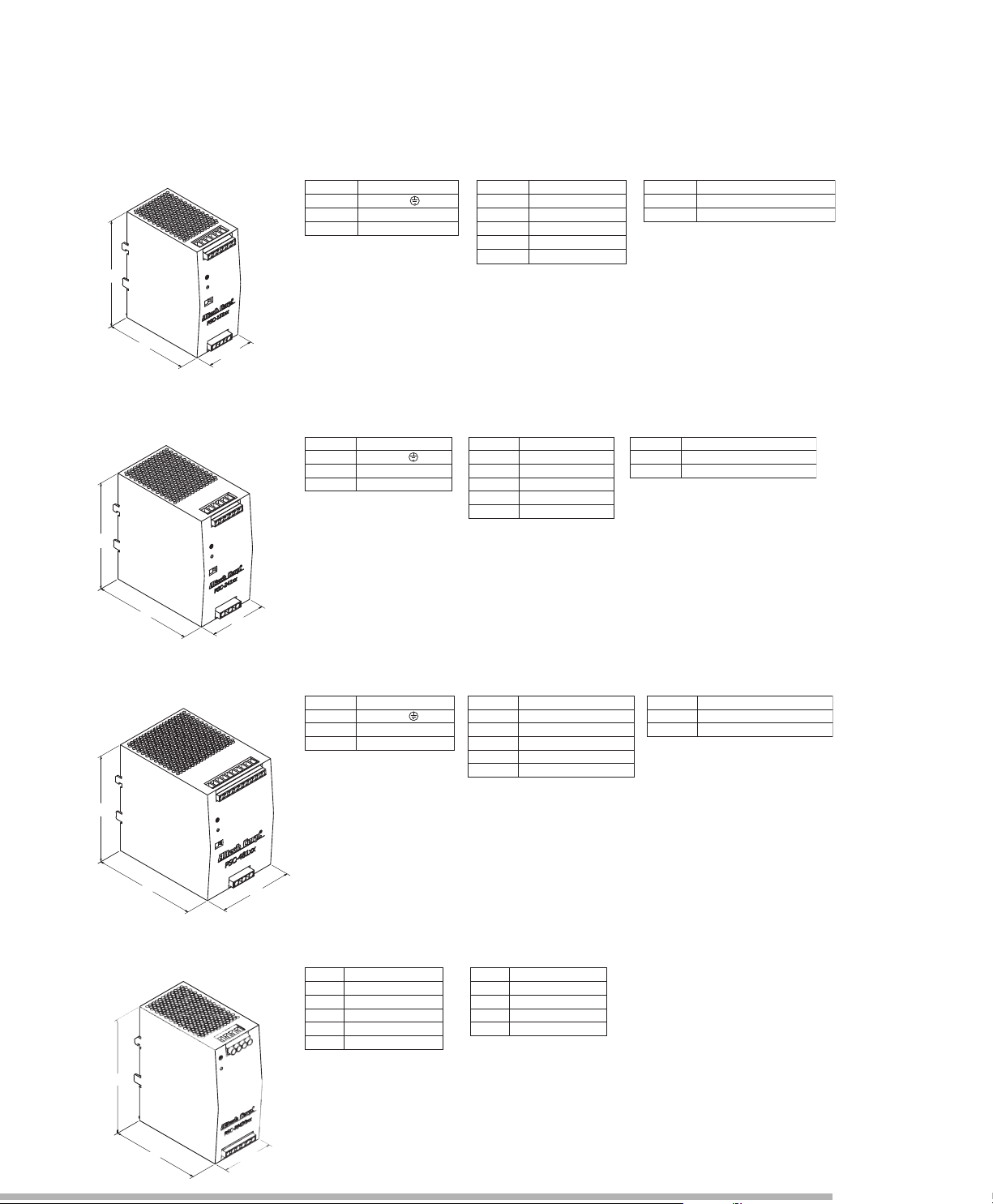
1
2
5
1
0
0
5
5
.5
Pin NO.
1
2
3
A
ssignment
AC/ L
FG
Termi na l Pi n No. As sig nmen t ( TB1 )
5,6
Assignment
INH+
R
elay Cont ac t
Termi nal Pi n No. As sig nmen t ( TB2 )
Pin NO.
1
3
INH-4
DC+
2
D
C-
AC/ N
Sw it ch No. Ass ignm ent
S
W NO.
SW1
Assignment
SW2
PEAK LOAD SETTI NG
REMOTE ON/OFF SETTING
Sw itc h N o. Assignment
SW NO.
S
W1
Assignment
S
W2
PEAK LOAD SETTIN G
REMOTE ON /OFF SETTING
5,6
Assignment
INH+
R
elay Cont a ct
Termi na l Pi n No. Assignment (TB2)
Pin NO.
1
3
I
NH-
4
D
C+
2
DC-
Pin NO.
1
2
3
Assignment
AC/ L
F
G
T
erminal Pin No. Assignment (TB1)
AC/ N
Pin NO.
1
2
3
Assi gnme nt
AC/ L
FG
Termi na l Pi n No. Ass ignm ent (T B1)
AC/ N
9,10
Assignment
INH+
D
C OK Si ngal
Terminal Pin No. Assignment (TB2)
Pin NO.
1-3
7
INH-
8
DC+
4-6
DC-
Sw itc h No. As sig nment
SW NO.
SW1
Assignment
SW2
PEAK LOAD SETTING
REMOT E ON/OF F SE TTI NG
SPECIFICATIONS
1
2
5
1
1
8
6
6
1
2
5
12
3
8
6
3
4
AssignmentPin No.
Terminal Pin. No Assignment (TB1) Terminal Pin. No Assignment (TB2)
Pin No.
Ass ignment
Vout +
Vout -
Ala rmA1
Ala rmA2
Ala rmB1
Ala rmB2
Vin A+
Vin B+
Vin-
1
2
2
1
6
5
3,4
1
2
5
1
0
0
5
5
.
5
PSC-151 Series
PSC-241 Series
Universal Input: 2.0A @ 115VAC / 1.0A @ 230VAC
Connection Input: 2 poles, single screw terminal
Connection Output: 2 poles, single screw terminal
Size (WxHxD): 55.5x12.5x100 mm (2.19x4.92x3.93 in.)
Packaging: 1/box; 0.72kg (1.6 lbs)
Universal Input: 2.6A @ 115VAC / 1.3A @ 230VAC
Connection Input: 2 poles, single screw terminal
Connection Output: 2 poles, single screw terminal
Size (WxHxD): 66x12.5x118 mm (2.6x4.9x4.65 in.)
Packaging: 1/box; 0.9kg (2.0 lbs)
PSC-481 Series
PSC-RM20
Universal Input: 5.0A @ 115VAC / 2.5A @ 230VAC
Connection Input: 2 poles, single screw terminal
Connection Output: 2 poles, single screw terminal
Size (WxHxD): 86x12.5x123 mm (3.4x4.9x4.85 in.)
Packaging: 1/box; 1.45kg (3.2 lbs)
Input: 2x20A @ 24VDC
Connection Input: 2 poles, single screw terminal
Connection Output: 2 poles, single screw terminal
Size (WxHxD): 55.5x12.5x100 mm (2.19x4.92x3.93 in.)
Packaging: 1/box; 0.72kg (1.6 lbs)
Page 3
OUTPUT
INPUT
PROTECTION
ENVIRONMENT
SAFETY & EMC
OUTPUT
PSC-151 Series
E205412
Features:
• Universal AC input (88-264V AC)
• Installed on DIN rail TS-35 / 7.5 or 15
• Built-in active PFC function, PF > 0.95
• 150% peak load capability
• 100% full load burn-in test
• Protection: SCP, OLP, OVP, OTP
• Two selectable peak load modes
• Built-in DC OK Relay contact
• Built-in Remote ON / OFF function
• 3 years warranty
• UL 508
Cat. No. PSC-15124 PSC-15148
DC VOLTAGE 24V 48V
RATED CURRENT 6.3A 3.2A
CURRENT RANGE 0~6.3A 0~3.2A
RATED POWER 150W 150W
PEAK CURRENT 9.45A 4.8A
PEAK POWER 225W (3sec.)
RIPPLE & NOISE (max) 240mVp-p 480mVp-p
VOLTAGE ADJ. RANGE -2% ~ +8% -2% ~ +8%
VOLTAGE TOLERANCE ±1.0% ±1.0%
LINE REGULATION ±0.5% ±0.5%
LOAD REGULATION ±1.0% ±1.0%
SETUP, RISE TIME 700ms, 30ms / 230VAC / 115VAC at full load
HOLD UP TIME (Typ.) 16ms / 230VAC; 16ms / 115VAC at full load
VOLTAGE RANGE 88 ~ 264VAC; 124 ~ 373VDC
FREQUENCY RANGE 47 ~ 63Hz
POWER FACTOR(Typ.) 0.9 / 230VAC; 0.98 / 115VAC at full load
EFFICIENCY (Typ.) 87% 87%
AC CURRENT (Typ.) 2.0A / 115VAC; 1.0A / 230VAC
INRUSH CURRENT (Typ.) 33A / 115VAC; 65A / 230VAC
LEAKAGE CURRENT <1mA/ 240VAC
OVERLOAD PROTECTION 105% ~ 150% rated output power for 3 sec and then shutdown in O/P with auto-recovery.
OVER VOLTAGE 29 ~ 33V 56 ~ 65V
OVER TEMPERATURE 95 ±5°C (TSW: detect on heatsink of power diode)
WORKING TEMP. -10 ~ +70°C (Refer to derating curve)
WORKING HUMIDITY 20 ~ 95% RH non-condensing
STORAGE TEMP. / HUMIDITY -40 ~ +85°C, 10 ~ 95% RH
TEMP. COEFFICIENT ±0.03% / °C (0 ~ 50°C)
VIBRATION 10 ~ 500Hz, 2G 10min. / 1cycle, 60min. each along X, Y, Z axes
SAFETY STANDARDS UL 508 / TUV EN 60950-1
WITHSTAND VOLTAGE I/P-O/P: 4242VDC, I/P-FG: 2121VDC, O/P-FG: 707VDC, O/P-DC OK: 707VDC
ISOLATION RESISTANCE I/P-O/P, I/P-FG, O/P-FG: >100M Ohms / 500VDC / 25°C / 70% RH
EMI CONDUCTION & RADIATION EN55022 (CISPR22) Class B
HARMONIC CURRENT EN61000-3-2, -3
EMS IMMUNITY Compliance to EN61000-4-2,3,4,5,6,8,11; ENV50204; EN55024; EN61000-6-2; (EN50082-2);
DC OK RELAY. CONTACT RATINGS (max) 60VDC / 0.3A, 30VDC / 1A, 30VAC / 0.5A resistive load
MTBF 62.7K HRS (MIL-HDBK-217F)
DIMENSION 55.5x125.2x99.8 mm (WxHxD)
PACKING 0.72kg; 12pcs / 12.8kg
COOLING Free air convection
3 seconds or 20% duty cycle max. and the average output power should not exceed the rate power.
Ripple & noise are measured at 20MHz of bandwidth by using a 12” twisted pair-wire terminated with a 0.1µF & 47µF parallel capacitor.
Tolerance: includes set up tolerance, line regulation and load regulation.
Derating may apply in low input voltage. Please check the derating curve for more details.
150% or greater rated power or short circuit is constant current limiting.
If O/P drops to 40% output then it auto-recover 5 times; if fault condition is not removed
during auto recovery, the system will shut down and needs to be restarted to recover.
Protection type: Latch-off mode, repower on to recover.
Protection type: Shut down o/p voltage, recovers automatically after temperature goes down
Installation clearance: 40mm from top, 20mm from bottom, 5mm from the left and right side are recommended when loaded
permanently with full power. In case the adjacent device is a heat source, 15mm clearance is recommended.
EN61204-3; heavy industry level; criteria A, MEET SEMI F47
The power supply is considered a component which will installed into a final equipment. The final equipment must be
re-confirmed that it still meets EMC directives.
All parameters NOT specially mentioned are measured at 230VAC input, rated load and 25°C of ambient temperature.
Page 4
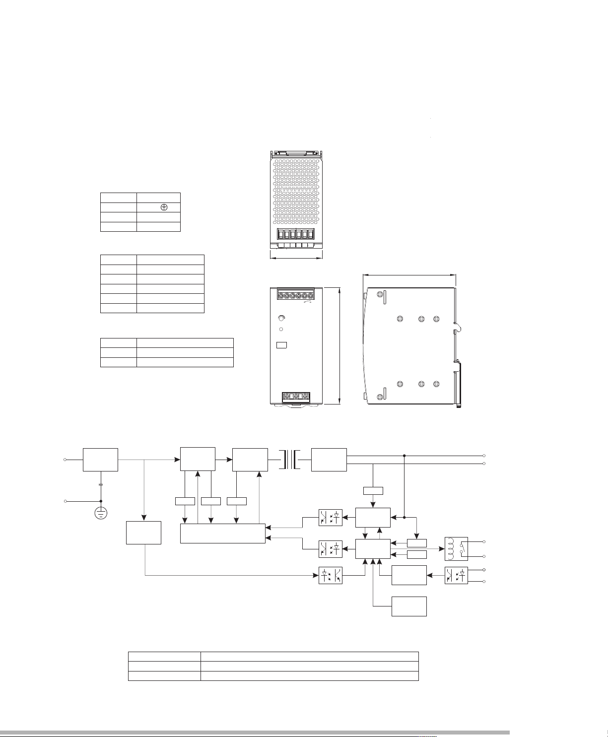
Mechanical Specification
Block Diagram
DC OK Relay Contact
Contact Close
Contact Open
Contact Ratings(max.)
When the output voltage reaches the adjusted output voltage.
When the output voltage drop below 45% rated output voltage.
30V/1A resistive load
EMI FILTER
&
RECTIFIERS
PFC
CIRCUIT
POWER
SWITCHING
O.C.P.
MICRO
CIRCUIT
RECTIFIERS
&
FILTER
O.V.P.
O.L.P.
O.L.P.
PWM & PFC CONTROL
DETECTION
CIRCUIT
O.T.P.
REMOTE
CONTROL
INH+
I/P
INH-
+V
-V
Relay C
PEAK LOAD
CONTROL
O.L.P.
AC
DETECTION
CIRCUIT
FG
DC ON
+
V
ADJ.
+
SW1
SW2
ON OFF
1
TB1
2
3
TB2
1234
5
6
R
elay Contact
U
nit : mm / inch
Pin NO.
1
2
3
Assignment
AC/L
FG
Terminal Pin No. Assignment (TB1)
5,6
Assignment
INH+
R
elay Contact
T
erminal Pin No. Assignment (TB2)
Pin NO.
1
3
INH-4
DC+
2
DC-
AC/N
Switch No. Assignment
SW NO.
SW1
A
ssignment
SW2
PEAK LOAD SETTING
REMOTE ON/OFF SETTING
5
5.5
9
9.8
125.
2
PSC-151 Series
Note: All dimensions are in millimeters, to convert to inches multiply by 0.03937.
Page 5
0
2
4
6
8
10
12
14
16
18
20
22
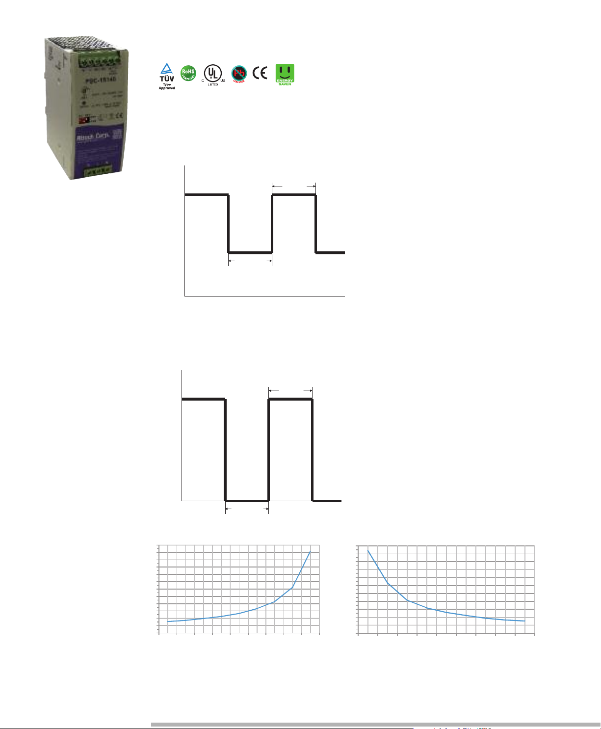
110% 115% 120% 125% 130%135% 140% 145% 150%
T- peak
CURVE B
I-peak
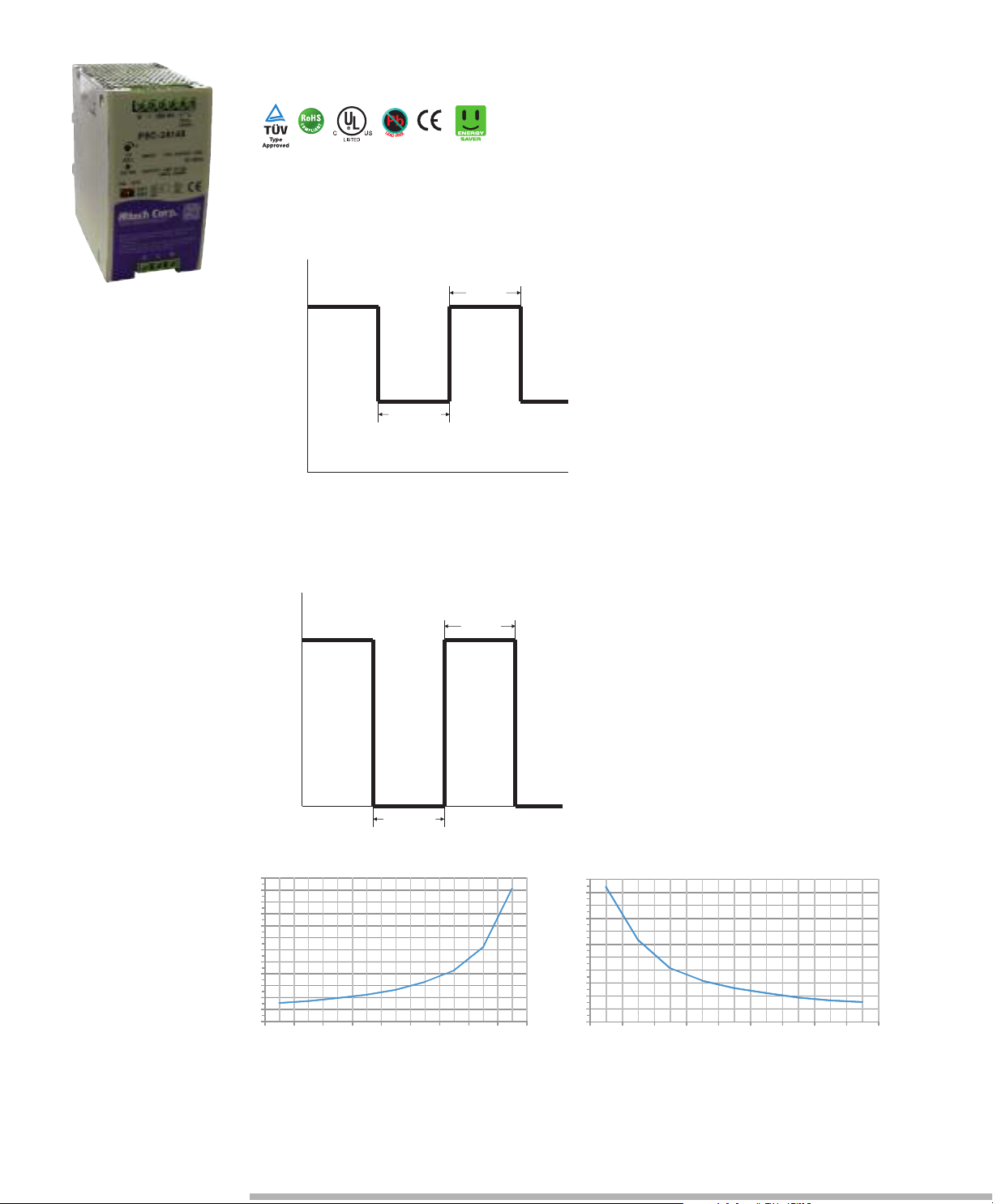
Peak Load SW1 ON (Mode1) Default setting
Peak Load SW2 OFF (Mode2)
I
T
I-normal
I-peak
T
-peak
T-normal
0
I
T
I-peak
T-peak
0
3 ~ 4 sec
0
2
4
6
8
10
12
14
16
18
20
22
24
10% 20% 30% 40% 50% 60% 70% 80% 90%
ormal
I-normal
CURVE A
T- n
T-peak presents while the unit is working within 110%~150%
Rating output power. See curve " B " for the variation in
T-peak between output current and holdup time. If T-peak is
more than the time setting in curve "B", the output current will
drop to the constant current limit (I-normal) that is 105% rating
power, meanwhile, I- normal and T-normal will be presenting.
See curve "A" for the timing back to I-Peak of T-normal and
this Mode can use for easy 2-stage battery charger.
T-peak presents while the unit is working within 110%~150%
Rating output power. See curve " B " for the variation in
T-peak between output current and holdup time. If T-peak is
more than the time setting in curve "B", the output current will
be shut down for 3~4 sec, then auto-recovery.
(Sec.)
L
o
a
d
(
%
)
(Sec.)
L
o
a
d
(
%
)
PSC-151 Series
E205412
Page 6

Remote ON/OFF
Derating Curve
Output derating VS input Voltage
T
he P SU can b e t urn ed ON/OF F b y u si n g the
"Re mo t e Con t ro l" function.
DISABLE
S
W2
ON
(Default Setting
)
INH+(3 PIN)/ INH-(4 PIN)
Output Status
SW ON (>2.5V)
E
NABLE
OFF
DISABLE
DISABLE
O
FF
SW OFF (<0.8V)
SW ON (>2.5V)
SW OFF (<0.8V)
ON
ENABLE
12
3
4
5
6
R
elay Contact
DC ON
+V
ADJ.
+
S
W1
S
W2
O
N OFF
TB2
SW
External Power Source
I = 6 ~ 20mA
Ambient Temperature (°C) AC=230 / 115VAC
0 10 20 30 40 50 60 70
(Vertical)
40
100
112 .5
150
Loa
d
(%)
For typ. 3sec
Continuous
-10
60
88 100 110 135 264VAC
Input Voltage (V) 60Hz Ta=25°C
230
40
50
60
70
80
Loa
d (%)
90
100
PSC-151 Series
Page 7

OUTPUT
INPUT
PROTECTION
ENVIRONMENT
SAFETY & EMC
OUTPUT
PSC-241 Series
E205412
Features:
• Universal AC input (88-264V AC)
• High efficiency 92% and low power dissipation
• Installed on DIN rail TS-35 / 7.5 or 15
• Built-in active PFC function, PF > 0.95
• 150% peak load capability
• 100% full load burn-in test
• Protection: SCP, OLP, OVP, OTP
• Two selectable peak load modes
• Built-in DC OK Relay contact
• Built-in Remote ON / OFF function
• 3 years warranty
• UL 508
Cat. No. PSC-24124 PSC-24148
DC VOLTAGE 24V 48V
RATED CURRENT 10A 5A
CURRENT RANGE 0~10A 0~5A
RATED POWER 240W 240W
PEAK CURRENT 15A 7.5A
PEAK POWER 360W (3sec.) Two selectable peak load modes
RIPPLE & NOISE (max) 150mVp-p 300mVp-p
VOLTAGE ADJ. RANGE -2% ~ +8% -2% ~ +8%
VOLTAGE TOLERANCE ±1.0% ±1.0%
LINE REGULATION ±0.5% ±0.5%
LOAD REGULATION ±1.0% ±1.0%
SETUP, RISE TIME 700ms, 30ms / 230VAC / 115VAC at full load
HOLD UP TIME (Typ.) 20ms / 230VAC; 20ms / 115VAC at full load
VOLTAGE RANGE 88 ~ 264VAC; 124 ~ 373VDC
FREQUENCY RANGE 47 ~ 63Hz
POWER FACTOR (Typ.) 0.96 / 230VAC; 0.96 / 115VAC at full load
EFFICIENCY (Typ.) 91% 92%
AC CURRENT (Typ.) 2.6A / 115VAC; 1.3A / 230VAC
INRUSH CURRENT (Typ.) 33A / 115VAC; 65A / 230VAC
LEAKAGE CURRENT <1mA/ 240VAC
OVERLOAD 105% ~ 150% rated output power for 3 sec and then shutdown in O/P with auto-recovery.
OVER VOLTAGE 28 ~ 33V 56 ~ 65V
OVER TEMPERATURE 95 ±5°C (TSW: detect on heatsink of power diode)
WORKING TEMP. -25 ~ +70˚C (Refer to output load derating curve)
WORKING HUMIDITY 20 ~ 95% RH non-condensing
STORAGE TEMP. / HUMIDITY -40 ~ +85˚C; 10 ~ 95% RH
TEMP. COEFFICIENT ±0.03% ˚C (0 ~ 50˚C)
VIBRATION 10 ~ 500Hz, 2G 10min. / 1cycle, 60 min. each long X,Y, Z axes
SAFETY STANDARDS UL508, TUV EN60950-1
WITHSTAND VOLTAGE I/P-O/P: 4242VDC I/P-FG2121VDC O/P-F/G: 707VDC O/P-DC OK: 707VDC
ISOLATION RESISTANCE I/P-O/P, I/P-FG, O/P-FG: > 100M Ohms / 500VDC / 25°C / 70% RH
EMI CONDUCTION & RADIATION EN55022:2006 Class B
HARMONIC CURRENT EN61000-3-2: 2006 Class A, ENG1000-3-3: 1995 +A1: 2001+A2: 2005
EMS IMMUNITY EN61204-3: 2000, EN55024: 1998+A1: 2001+A2: 2003 light industry level, criteria A
DC OK RELAY CONTACT RATINGS (max) 60VDC / 0.3A, 30VDC / 1A, 30VAC / 0.5A resistive load
MTBF 57K HRS (MIL-HDBK-217F)
DIMENSION 65.8x125.2x117.7 mm (WxHxD)
PACKING 0.9kg; 12pcs / 12.8kg
COOLING Free air convection
3 seconds or 20% duty cycle Max. The average output power should not exceed the rate power.
Ripple & noise are measured at 20MHz of bandwidth by using a 12” twisted pair-wire terminated with a 0.1µF & 47µF parallel capacitor.
olerance: includes set up tolerance, line regulation and load regulation.
T
Derating may apply in low input voltage. Please check the derating curve for more details.
150% or greater rated power or short circuit is constant current limiting.
If O/P drops to 40% output then it auto-recover 5 times; if fault condition is not removed
during auto recovery, the system will shut down and needs to be restarted to recover.
Protection type: Shut down O/P voltage with auto-recovery
Protection type: Shut down o/p voltage, recovers automatically after temperature goes down
Installation clearances: 40mm on top, 20mm on the bottom, 5mm on the left and right side are recommended when loaded
permanently with full power. In case the adjacent device is a heat source, 15mm clearance is recommended.
The power supply is considered a component which will installed into a final equipment. The final equipment must be
re-confirmed that it still meets EMC directives.
All parameters NOT specially mentioned are measured at 230VAC input, rated load and 25°C of ambient temperature.
Page 8

M
echanical Specification
Block Diagram
DC OK Relay Contact
U
nit : mm / inch
S
witch No. Assignment
SW NO.
SW1
Assignment
SW2
PEAK LOAD SETTING
REMOTE ON/OFF SETTING
5,6
Assignment
INH+
R
elay Contact
Terminal Pin No. Assignment (TB2)
Pin NO.
1
3
INH-4
DC+
2
DC-
P
in NO.
1
2
3
Assignment
AC/L
FG
Terminal Pin No. Assignment (TB1)
AC/N
1
17.7
6
5.80
1
2
3
4
5
6
TB2
1
TB1
2
3
Relay Contact
DC ON
+
V
ADJ.
+
S
W1
SW2
ON OFF
65.8
117 .7
125
.2
EMI FILTER
&
RECTIFIERS
PFC
CIRCUIT
POWER
SWITCHING
O.C.P.
MICRO
CIRCUIT
RECTIFIERS
&
FILTER
O.V.P.
PWM POWER
CONTROL
PFC
CONTROL
O.L.P.
O.L.P.
ACTIVE
INRUSH
CURRENT
LIMITING
AC
DETECTION
CIRCUIT
DETECTION
CIRCUIT
O.T.P.
REMOTE
CONTROL
INH+
I/P
FG
INH+
INH-
+V
-V
Relay Contact
PEAK LOAD
CONTROL
Contact Close
Contact Open
Contact Ratings(max.)
When the output voltage reaches the adjusted output voltage.
When the output voltage drop below 45% rated output voltage.
30V/1A resistive load
PSC-241 Series
Note: All dimensions are in millimeters, to convert to inches multiply by 0.03937.
Page 9
0
2
4
6
8
10
12
14
16
18
20
22
110% 115% 120% 125% 130%135% 140% 145% 150%
T- peak
CURVE B
I-peak
Peak Load SW1 ON (Mode1) Default setting
Peak Load SW2 OFF (Mode2)
I
T
I-normal
I-peak
T-peak
T-normal
0
I
T
I-peak
T-peak
0
3 ~ 4 sec
0
2
4
6
8
10
12
14
16
18
20
22
24
10% 20% 30% 40% 50% 60% 70 % 80% 90%
ormal
I-normal
CURVE A
T- n
T-peak presents while the unit is working within 110%~150%
R
ating output power. See curve " B " for the variation in
T-peak between output current and holdup time. If T-peak is
more than the time setting in curve "B", the output current will
drop to the constant current limit (I-normal) that is 105% rating
power, meanwhile, I- normal and T-normal will be presenting.
See curve "A" for the timing back to I-Peak of T-normal and
this Mode can use for easy 2-stage battery charger.
T-peak presents while the unit is working within 110%~150%
Rating output power. See curve " B " for the variation in
T-peak between output current and holdup time. If T-peak is
more than the time setting in curve "B", the output current will
be shut down for 3~4 sec, then auto-recovery.
(Sec.)
L
o
a
d
(
%
)
(Sec.)
L
o
a
d
(
%
)
PSC-241 Series
E205412
Page 10

R
emote ON/OFF
Derating Curve
Output derating VS input Voltage
T
he P SU can b e t urn ed ON/OF F b y u si n g the
"Re mo t e Con t ro l" function.
D
ISABLE
SW2
ON
(Default Setting
)
INH+(3 PIN)/ INH-(4 PIN)
Output Status
SW ON (>2.5V)
E
NABLE
O
FF
D
ISABLE
DISABLE
OFF
SW OFF (<0.8V)
SW ON (>2.5V)
SW OFF (<0.8V)
ON
ENABLE
Ambient Temperature (°C) AC=230 / 115VAC
0 10 20 30 40 50 60 70
(Vertical)
40
100
112 .5
1
50
Loa
d
(%)
For typ. 3sec
Continuous
-10
60
88 100 110 135 264VAC
Input Voltage(V)60Hz Ta=25°C
230
40
50
60
70
80
Loa
d (%)
90
100
12
3
4
5
6
TB2
DC ON
+
V
A
DJ.
+
SW1
SW2
ON OFF
S
W
External Power Source
I = 6 ~ 20mA
DC OK
PSC-241 Series
Page 11

OUTPUT
INPUT
PROTECTION
ENVIRONMENT
SAFETY & EMC
OUTPUT
PSC-481 Series
E205412
Features:
• Universal AC input (88-264V AC)
• Installed on DIN rail TS-35 / 7.5 or 15
• Built-in active PFC function, PF > 0.95
• 150% peak load capability
• Protection: SCP, OLP, OVP, OTP
• Two selectable peak load modes
• Built-in DC OK (Open Collector Signal)
• Built-in Remote ON / OFF function
• 3 years warranty
• UL 508
Cat. No. PSC-48124 PSC-48148
DC VOLTAGE 24V 48V
RATED CURRENT 20A 10A
CURRENT RANGE 0~20A 0~10A
RATED POWER 480W 480W
PEAK CURRENT 30A 15A
PEAK POWER 720W (3sec.) Two selectable peak load modes
RIPPLE & NOISE (max) 240mVp-p 480mVp-p
VOLTAGE ADJ. RANGE -5% ~ +5%
VOLTAGE TOLERANCE ±1.0% ±1.0%
LINE REGULATION ±0.5% ±0.5%
LOAD REGULATION ±1.0% ±1.0%
SETUP, RISE TIME 800ms, 100ms / 230VAC / 115VAC at full load
HOLD UP TIME (Typ.) 16ms / 230VAC; 16ms / 115VAC at full load
VOLTAGE RANGE 88 ~ 264VAC; 124 ~ 373VDC
FREQUENCY RANGE 47 ~ 63Hz
POWER FACTOR (Typ.) 0.96 / 230VAC / 115VAC at full load
EFFICIENCY (Typ.) 93% 94%
AC CURRENT (Typ.) 5.0A / 115VAC; 2.5A / 230VAC
INRUSH CURRENT (Typ.) 33A / 115VAC; 65A / 230VAC
LEAKAGE CURRENT < 1mA/ 240VAC
OVERLOAD 105% ~ 150% rated output power for 3 sec and then shutdown in O/P with auto-recovery.
OVER VOLTAGE 29 ~ 33V 56 ~ 65V
OVER TEMPERATURE 95 ±5°C (TSW: detect on heatsink of power diode)
WORKING TEMP. -20 ~ +70˚C (Refer to output load derating curve)
WORKING HUMIDITY 20 ~ 95% RH non-condensing
STORAGE TEMP. / HUMIDITY -40 ~ +85˚C; 10 ~ 95% RH
TEMP. COEFFICIENT ±0.03% ˚C (0 ~ 50˚C)
VIBRATION 10 ~ 500Hz, 2G 10min. / 1cycle, 60 min. each long X,Y, Z axes
SAFETY STANDARDS UL 508 / EN 60950-1
WITHSTAND VOLTAGE I/P-O/P: 4242VDC, I/P-FG: 2121VDC, O/P-FG: 707VDC, O/P-DC OK: 707VDC
ISOLATION RESISTANCE I/P-O/P, I/P-FG, O/P-FG: >100M Ohms / 500VDC / 25°C / 70% RH
EMI CONDUCTION & RADIATION EN 55022 (CISPR22), EN 61000-6-3
HARMONIC CURRENT EN61000-3-2, -3-3
EMS IMMUNITY IEC 61000-4-2, 3, 4, 5, 6, 8, 11; EN 61000-6-1; EN 61204-3
DC OK RELAY CONTACT RATINGS (max) 60VDC / 0.3A, 30VDC / 1A, 30VAC / 0.5A resistive load
DIMENSION 86.3x124.8x123.4 mm (WxHxD)
PACKING 1.45kg; 8pcs / 12kg
3 seconds or 20% duty cycle Max. The average output power should not exceed the rate power.
Ripple & noise are measured at 20MHz of bandwidth by using a 12” twisted pair-wire terminated with a 0.1µF & 47µF parallel capacitor.
olerance: includes set up tolerance, line regulation and load regulation.
T
Derating may apply in low input voltage. Please check the derating curve for more details.
150% or greater rated power or short circuit is constant current limiting.
If O/P drops to 40% output then it auto-recover 5 times; if fault condition is not removed
during auto recovery, the system will shut down and needs to be restarted to recover.
Protection type: Latch-off mode.
Protection type: Shut down o/p voltage, recovers automatically after temperature goes down
Installation clearance: 40mm from top, 20mm from the left and right side are recommended when
loaded permanently with full power. In case the adjacent device is a heat sorce, 15mm clearance is recomended.
The power supply is considered a component which will installed into a final equipment. The final equipment must be
re-confirmed that it still meets EMC directives.
All parameters NOT specially mentioned are measured at 230VAC input, rated load and 25°C of ambient temperature.
Page 12

Mechanical Specification
Block Diagram
DC OK Relay Contact
U
nit : mm / inch
EMI FILTER
&
R
ECTIFIERS
PFC
CIRCUIT
POWER
S
WITCHING
O.C.P.
MICRO
CIRCUIT
RECTIFIERS
&
FILTER
O.V.P.
PWM POWER
CONTROL
PFC
CONTROL
O.L.P.
O.L.P.
ACTIVE
iNRUSH
CURRENT
LIMITING
AC
DETECTION
CIRCUIT
DETECTION
CIRCUIT
O.T.P.
REMOTE
CONTROL
INH+
I/P
FG
INH+
INH-
+
V
-V
DC OK S ingal
PEAK LOAD
CONTROL
Contact Ratings(max.)
CTR : MIN. 50% at IF = 5mA, VCE = 5V
Isolation Voltage
Between input and output Viso = 3750Vrms
Pin NO.
1
2
3
Assignment
AC/L
F
G
Terminal Pin No. Assignment (TB1)
AC/N
9,10
Assignment
INH+
DC OK Singal
Termin al P in N o. Assignment (TB2)
Pin NO.
1-3
7
INH-
8
DC+
4-6
DC-
S
witch No. Assignment
SW NO.
S
W1
Assignment
SW2
PEAK LOAD SETTING
R
EMOTE ON/OFF SETTING
86.3
123.4
124.8
1
TB1
2
3
DC ON
+V
A
DJ.
+
O
N OFF
S
W1
S
W2
12
3456
TB2
DC OK
7
8910
PSC-481 Series
Note: All dimensions are in millimeters, to convert to inches multiply by 0.03937.
Page 13

0
2
4
6
8
10
12
14
16
18
20
22
110% 115% 120% 125% 130%135% 140% 145% 150%
T- peak
CURVE B
I-peak
Peak Load SW1 ON (Mode1) Default setting
Peak Load SW2 OFF (Mode2)
I
T
I-normal
I-peak
T-peak
T-normal
0
I
T
I-peak
T-peak
0
3 ~ 4 sec
0
2
4
6
8
10
12
14
16
18
20
22
24
10% 20% 30% 40% 50% 60% 70 % 80% 90%
ormal
I-normal
CURVE A
T- n
T-peak presents while the unit is working within 110%~150%
Rating output power. See curve " B " for the variation in
T-peak between output current and holdup time. If T-peak is
m
ore than the time setting in curve "B", the output current will
drop to the constant current limit (I-normal) that is 105% rating
power, meanwhile, I- normal and T-normal will be presenting.
S
ee curve "A" for the timing back to I-Peak of T-normal and
this Mode can use for easy 2-stage battery charger.
T-peak presents while the unit is working within 110%~150%
Rating output power. See curve " B " for the variation in
T-peak between output current and holdup time. If T-peak is
more than the time setting in curve "B", the output current will
be shut down for 3~4 sec, then auto-recovery.
(Sec.)
L
o
a
d
(
%
)
(Sec.)
L
o
a
d
(
%
)
PSC-481 Series
E205412
Page 14

Remote ON/OFF
Derating Curve
Output derating VS input Voltage
Th e PSU ca n b e tur ned ON /O F F by usi ng th e
"
Re mo t e Con t ro l" function.
DISABLE
SW2
ON
(
Default Setting
)
INH+(3 PIN)/ INH-(4 PIN)
Output Status
S
W ON (>2.5V)
ENABLE
OFF
D
ISABLE
D
ISABLE
OFF
S
W OFF (<0.8V)
S
W ON (>2.5V)
SW OFF (<0.8V)
ON
ENABLE
Ambient Temperature (°C) AC=230 / 115VAC
0 10 20 30 40 50 60 70
(Vertical)
40
100
1
12.5
1
50
Loa
d
(%)
For typ. 3sec
Continuous
-10
60
88 100 110 135 264VAC
Input Voltage(V)60Hz Ta=25°C
230
40
50
60
70
80
Loa
d (%)
90
100
12
3
4
5
6
TB2
DC ON
+V
ADJ.
+
SW1
S
W2
ON OFF
SW
External Power Source
I = 6 ~ 20mA
DC OK
PSC-481 Series
Page 15

PSC-RM20
B
Vout+
Vin/Vout-
Vin A+
RELAY
A
RELAY
+
+
AlarmA
Block Diagram
OUTPUT
INPUT
PROTECTION
ENVIRONMENT
SAFETY & EMC
OUTPUT
Specifications
Features:
• Suitable for redundant operation of 24V system
• Installed on DIN Rail TS35 / 7.5 or 15
• Relay contact signal output and LED indicator for input
failure alarm
• Cooling by free air convection
• 3 year warranty
Cat. No. PS-RDN20
REVERSE VOLTAGE (max.) 30V
OUTPUT CURRENT (max.) 20A
VOLTAGE DROP 0.5V
LED INDICATORS Two green LED’s indicating each input is OK or fail
INPUT VOLTAGE RANGE 21 ~ 28V
NUMBER OF INPUTS Two
INPUT CURRENT (max.) 20A per input
INPUT VOLTAGE ALARM When input is ≥ 20V (±5%) or ≤ 30V (±5%) relay contacts
RELAY CONTACT RATING (max.) 30VDC, 1A
WORKING TEMP. -20 ~ +70˚C
WORKING HUMIDITY 20 ~ 90% RH non-condensing
STORAGE TEMP., HUMIDITY -40 ~ +85˚C, 10 ~ 95% RH
VIBRATION 10 ~ 500Hz, 2G 10min./1cycle, 60 min. each long X,Y, Z axes
MOUNTING Compliance to IEC60068-2-6
WITHSTAND VOLTAGE Terminal- Chassis: 0.5KVAC, Relay Contacts- Terminal: 0.5KVAC
ISOLATION RESISTANCE Terminal- Chassis: ≥100M Ohms / 500VDC (25˚C; 70% RH)
EMI CONDUCTION & RADIATION Compliance to EN55022 (CISPR22) Class B
EMS IMMUNITY Compliance to EN61000-4-2,3,4,5,6,8; ENV50204; heavy industry level; criteria A,
MTBF 996.8Khrs min. MIL-HDBK-217K (25˚C)
DIMENSION 55.5x125.2x100mm (WxHxD)
PACKING 0.45Kg; 20pcs / 11Kg / 1.29CUFT
All parameters NOT specially mentioned are measured at 24V DC input, rated load and 25˚C of ambient temperature.
Page 16

-20010203045506070
20
40
60
80
100
(VERTIC AL)
3
4
A
ssignmentPin No.
Terminal Pin. No Assignment (TB1) Terminal Pin. No Assignment (TB2)
P
in No.
A
ssi gn ment
V
out +
Vout -
A
lar mA1
A
lar mA2
Ala rmB1
A
lar mB2
Vin A+
Vin B+
Vin -
1
2
2
1
6
5
3,4
Mechanical Specification
Derating Curve
Applications
PSU
USPUSP
USPUSP PSUPSUUSPUSP PSU
Load
Load
Loa d
VouttuoVtuoV Vout
tuoVtuoV
Vin A
AniVAniV
Vin A Vin A
..... .........
100
55.50
1
2
9
1
2
5
Note: All dimensions are in millimeters, to convert to inches multiply by 0.03937.
 Loading...