

Page 1
QUICK START GUIDE
MODEL: AP6-Pro
Page 2
Before You Begin
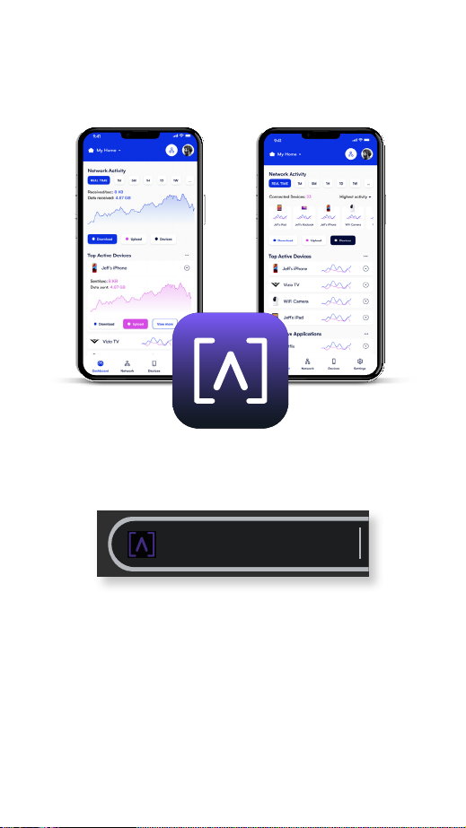
Download the Alta app on your mobile device,
and create your free Alta account.
You may also visit manage.alta.inc to manage
your Alta devices.
manage.alta.inc
1
Page 3
Package Contents
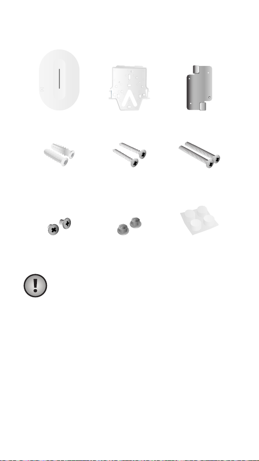
AP6-Pro Mounting Plate Ceiling Mount
Anchors
(Qty. 2)
T-Bar Screws Nuts Rubber Feet
Wall-Mount
Screws (Qty. 2)
Ceiling Tile
Screws (Qty. 2)
Note: Be sure to use the included
mounting hardware for installation.
Installation Requirements
• Ethernet cabling (CAT 5 or above)
• 48V PoE+ switch or PoE injector
• Phillips screwdriver
• Drill and drill bit for wall or ceiling mounting
2
Page 4
Hardware Overview
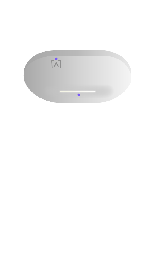
Front
Logo Indicator
LED
Logo Indicator If you need to remove the AP
from the mount, use a flat blade screwdriver to
disengage the Mounting Plate here.
LED Illuminates white by default when AP is
online and functional. Can be changed to blue,
white, or off in the Alta app or management
interface. Flashes when booting.
3
Page 5
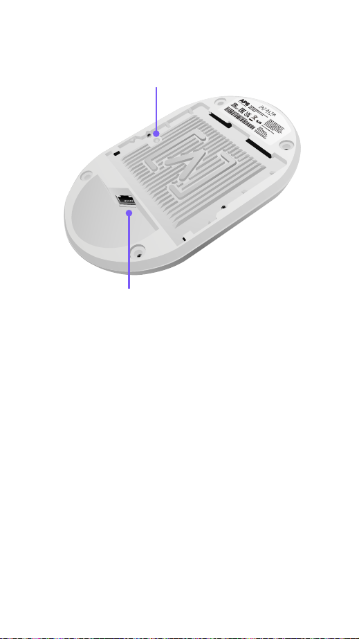
Back
RESET
PoE
Reset Button
Ethernet Port
Reset Button Press down for 10 seconds until
the LED begins flashing to reset the AP to
factory defaults.
Ethernet Port Connects to an Ethernet cable
from your PoE+ Switch. An optional 48V, 0.5A
adapter can be purchased and used to power
the AP.
4
Page 6
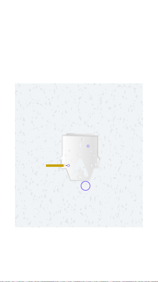
Hardware Installation
Ceiling Tile Mount
1. Remove the appropriate ceiling tile.
2. Align the Mounting Plate in the desired
location flat on the tile (typically centered).
Mark the areas indicated below for the
screws and the Ethernet cable.
5
Page 7
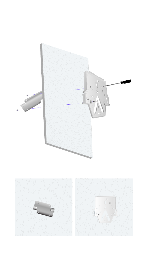
3. Secure the Mounting Plate to the Ceiling
Mount with the ceiling tile between using
the two Ceiling Tile Screws and the two Nuts.
Assembled Top View Assembled Bottom View
Proceed to “Connecting The AP” on page 13
6
Page 8
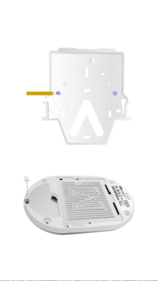
Wall Mount
1. Position the Mounting Plate in the desired
location and use a pencil to mark the holes.
2. If running cabling along the wall, remove the
notch on the AP.
RESET
PoE
7
Page 9
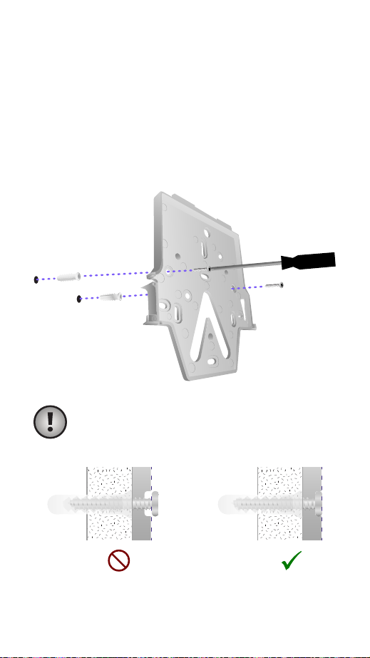
3. Secure the Mounting Plate to the wall
using the Wall-Mount Screws and a Phillips
screwdriver. Be sure to use the screws
included with the product.
If mounting on drywall, use the anchors to
ensure secure mounting. Use a 6 mm drill
bit to drill the holes for the anchors and
insert them in the wall.
Note: Ensure the included Wall-Mount
Screws are flush with Mounting Plate.
Proceed to “Connecting The AP” on page 13
8
Page 10
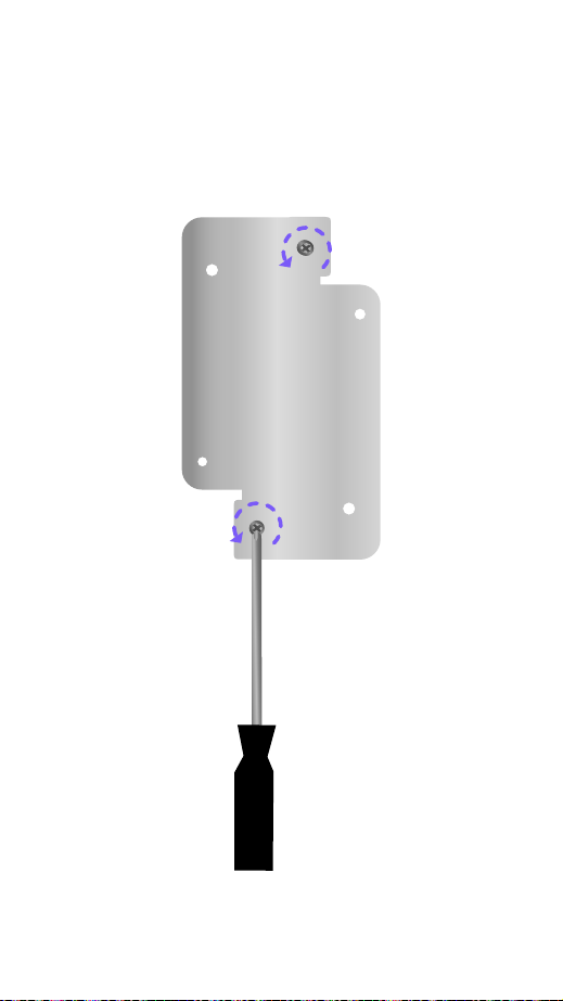
T-Bar Ceiling TIle Mount
1. Use a small Phillips head screwdriver to
loosen the two pre-installed screws on the
Ceiling Mount to allow enough clearance for
the T-Bar.
9
Page 11
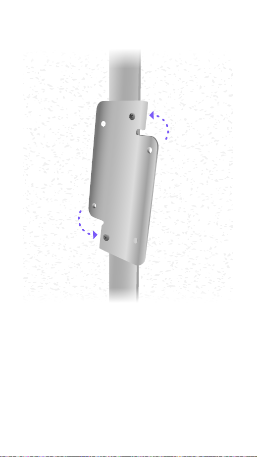
2. Rotate the Ceiling Mount around the T-Bar.
10
Page 12
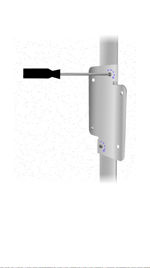
3. Tighten both screws using a Phillips
screwdriver.
11
Page 13
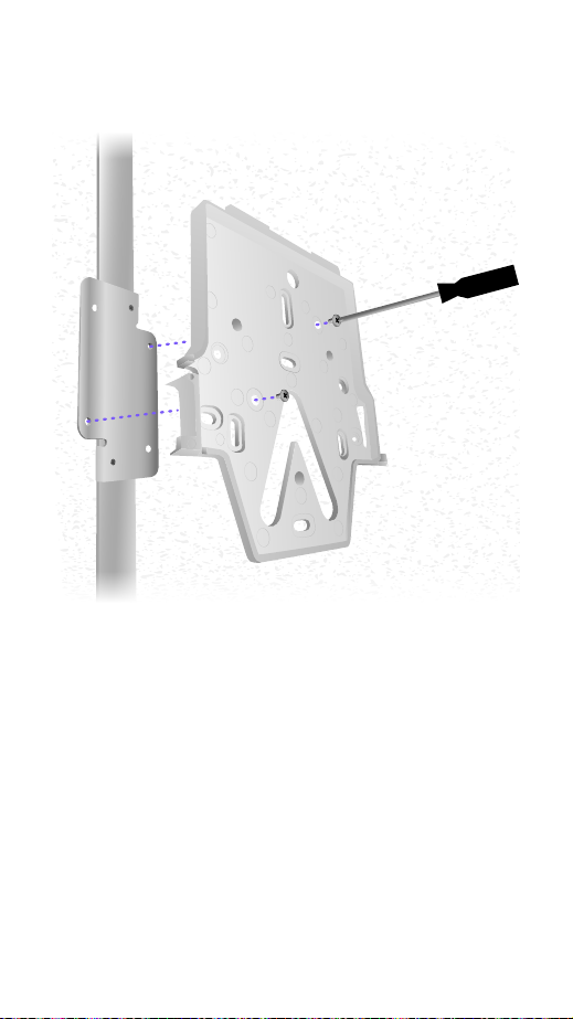
4. Connect the Mounting Plate to the Ceiling
Mount with the T-Bar Screws.
Proceed to “Connecting The AP” on page 13
12
Page 14
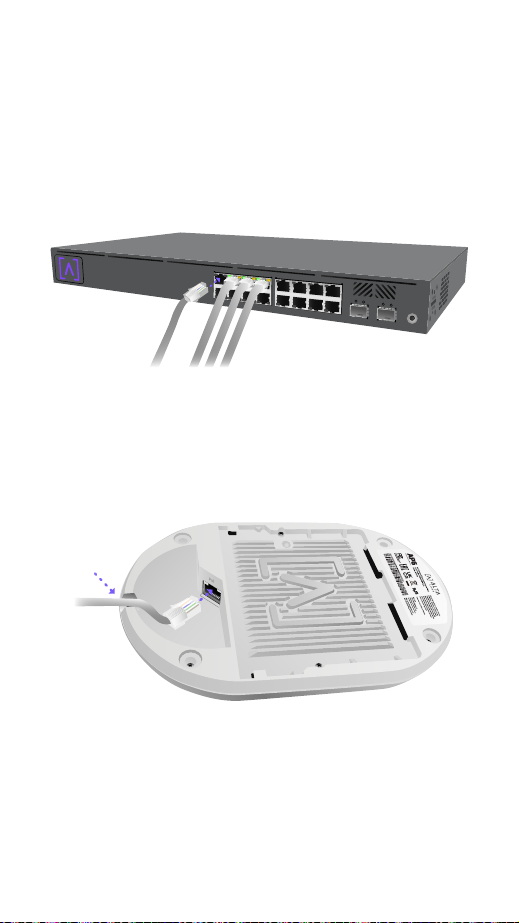
Connecting The AP
The AP is powered over Ethernet, it can be
powered by a PoE+ Switch or using an optional
48V, 0.5A PoE Injector.
1. Connect an Ethernet cable from your PoE+
Switch (or optional PoE Injector).
2. Connect the other end to the Ethernet
Port on the AP. If mounting on the wall,
the Ethernet cable can be fed through the
removable notch area.
RESET
PoE
13
Page 15
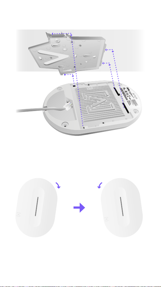
3. Align the AP with the Mounting Plate.
RESET
PoE
1
1
4. Slightly tilt the AP right and then left as you
slide the AP down the Mounting Plate to
lock it into place.
14
Page 16
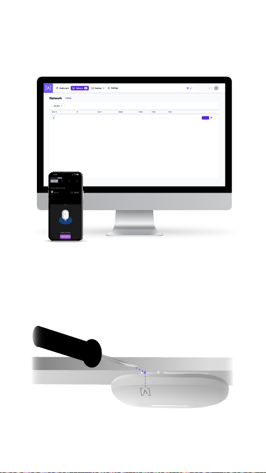
Set Up Your Device
1. Follow the instructions in the Alta app or
management interface to set up your AP.
Home Base
bcb923123426
New AP
1.0
Set Up
Disconnecting the AP
If you need to remove the AP from the mount,
use a flat blade screwdriver to disengage the
Mounting Plate at the logo indicator.
15
Page 17
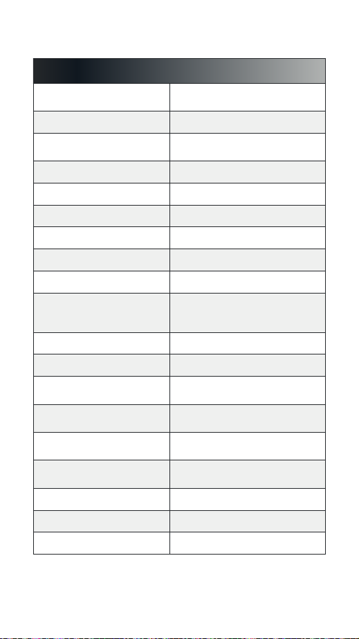
Specifications
Model: AP6-Pro
Dimensions
Weight 0.4 kg (0.9 lbs)
Mount Material
Weatherproofing IP54
Network Interface Ethernet, WiFi, Bluetooth
Management Interface (1) GbE RJ45 Port
Button(s) Reset/Factory Reset
LED Blue, White
Power Method PoE+
Power Supply
Supported Voltage Range 42.5-57V DC
Max. Power Consumption 25W
Max. Transmit Power
MIMO
Throughput Rate
Mounting
Operating Temperature -30 to 60° C (-22 to 140° F)
Operating Humidity 5 to 95% Noncondensing
Certifications CE, FCC, IC
190mm (7.5") x 125mm (4.9")
32mm (1.25")
Ceiling/Wall: Polycarbonate
Drop Ceiling: Steel
PoE+ Enabled Network Switch
or 48V, 0.5A PoE Adapter
(Optional)
2.4 GHz: 23 dBm @2NSS
5 GHz: 26 dBm @4NSS
2.4 GHz: 2 x 2
5 GHz: 4 x 4
2.4 GHz: Up to 573 Mbps
5 GHz: Up to 5.8 Gbps
Wall, ceiling, drop-ceiling,
table top
16
Page 18

Compliance
Federal Communication Commission
Interference Statement
This product has been tested and found to comply with the
limits for a Class B digital device pursuant to Part 15 of the
FCC Rules. These limits are designed to provide reasonable
protection against harmful interference when the
equipment is operated in a commercial environment. This
equipment generates, uses, and can radiate radio frequency
energy and, if not installed and used in accordance with
the instruction manual, may cause harmful interference
to radio communications. Operations of this equipment
in a residential area is likely to cause harmful interference
in which case the user will be required to correct the
interference at his own expense.
However, there is no guarantee that interference will not
occur in a particular installation. If this equipment does
cause harmful interference to radio or television reception,
which can be determined by turning the equipment off and
on, the user is encouraged to try to correct the interference
by one or more of the following measures:
• Reorient or relocate the receiving antenna.
• Increase the separation between the equipment and
receiver.
• Connect the equipment into an outlet on a circuit
different from that to which the receiver is connected.
• Consult the dealer or an experienced radio/TV technician
for help.
FCC Caution
This device complies with Part 15 of the FCC Rules.
Operation is subject to the following two conditions:
(1) This device may not cause harmful interference, and
(2) This device must accept any interference received,
including interference that may cause undesired
operation.
This device is restricted to indoor use.
Non-Modification Statement
Changes or modifications not expressly approved by the
party responsible for compliance could void the user’s
authority to operate the equipment.
17
Page 19

FCC Radiation Statement
This equipment complies with FCC radiation exposure limits
set forth for an uncontrolled environment. This equipment
should be installed and operated with minimum distance
20cm between the radiator and your body.
CAN ICES-003(B) / NMB-003(B)
This device contains licence-exempt transmitter(s)/
receiver(s) that comply with Innovation, Science and
Economic Development Canada’s licence-exempt RSS(s).
Operation is subject to the following two conditions:
(1) This device may not cause interference.
(2) This device must accept any interference, including
interference that may cause undesired operation of the
device.
L’émetteur/récepteur exempt de licence contenu dans
le présent appareil est conforme aux CNR d’Innovation,
Sciences et Développement économique Canada
applicables aux appareils radio exempts de licence.
L’exploitation est autorisée aux deux conditions suivantes :
(1) L’appareil ne doit pas produire de brouillage;
(2) L’appareil doit accepter tout brouillage radioélectrique
subi, même si le brouillage est susceptible d’en
compromettre le fonctionnement.
The device for operation in the band 5150-5250 MHz is
only for indoor use to reduce the potential for harmful
interference to co-channel mobile satellite systems.
Les dispositifs fonctionnant dans la bande 5150-5250 MHz
sont réservés uniquement pour une utilisation à l’intérieur
afin de réduire les risques de brouillage préjudiciable aux
systèmes de satellites mobiles utilisant les mêmes canaux.
ISED Radiation Exposure Statement:
This equipment complies with IC RSS-102 radiation
exposure limits set forth for an uncontrolled environment.
This equipment should be installed and operated with
minimum distance 20cm between the radiator & your body.
Cet équipement est conforme aux limites d’exposition
aux rayonnements IC établies pour un environnement
non contrôlé. Cet équipement doit être installé et utilisé
avec un minimum de 20cm de distance entre la source de
rayonnement et votre corps.
The transmitter module may not be co-located with any
other transmitter or antenna.
Le module émetteur peut ne pas être coïmplanté avec un
autre émetteur ou antenne.
18
Page 20

The Country Code Selection feature is disabled for products
marketed in the US/Canada.
For product available in the USA/Canada market, only
channel 1~11 can be operated. Selection of other channels is
not possible.
Pour les produits disponibles aux États-Unis / Canada du
marché, seul le canal 1 à 11 peuvent être exploités. Sélection
d’autres canaux n’est pas possible.
19
Page 21
Community Forum
forum.alta.inc
Technical Support
help.alta.inc
All specifications are subject to change without notice.
Alta Labs products are sold with a limited warranty:
© 2023 Soundvision Technologies. All rights reserved.
Alta Labs is a trademark of SoundvisionTechnologies.
alta.inc/warranty
 Loading...