

Page 1

mb1_serv.ing
Alsatom MB1A/MC MB1/MC
INDEX
EQUIPMENT REQUIRED................................................................................... 2
A) PRELIMINARY PROCEDURE......................................................................... 2
B) LOW VOLTAGE POWER SUPPLY (board 801260-801260/a) ............................ 2
1) Testing power supply voltage +5V and +15V (TP1, TP2). .......................... 2
C) MICROCONTROLLER (board 801261-801262) ............................................... 2
1) Testing once equipment is turned on ......................................................... 2
3) Calibrating Vref voltage........................................................................... 3
4) Testing RF modulation signal.................................................................... 3
4) ONE SHOT timing test (single pulse) ......................................................... 4
5) superpulsed timing test ........................................................................... 4
E) POWER SUPPLY (board 801260-801260/a) ................................................... 5
1) Calibrating reference voltage Vrefa ........................................................... 5
2) Testing power supply driving PWM signal .................................................. 5
3) Calibrating minimum voltage .................................................................... 5
4) Calibrating maximum voltage ................................................................... 5
F) RADIOFREQUENCY (board 801260-801260/a) ............................................... 5
1) Testing neutral plate circuit...................................................................... 5
2) Testing working frequency....................................................................... 6
3)Calibrating the sloped signal (saw-tooth signal) ............................................ 6
4) Calibrating dead time .............................................................................. 6
5) testing the RF power amplifier.................................................................. 7
6) Calibrating current limiter ........................................................................ 7
7) Testing output power.............................................................................. 7
8) Calibrating maximum RF leakage current.................................................... 7
9) Bipolar coagulation test ........................................................................... 7
G) CALIBRATING RF PROTECTION SYSTEMS .................................................... 8
1) Protection from malfunction caused by modulation signal ............................. 8
2) Protection from malfunction caused by power supply................................... 8
H) CHECKING THE AUDIO SIGNAL LEVEL ......................................................... 8
I) CHECKING RF CURRENT LEAKAGE................................................................ 8
CURVES OF POWER CHANGES BY CHANGING THE LOADS
(FROM 50 TO 2000 OHMS) ............................................................................ 9
CURVES OF POWER INCREMENT (WITH NOMINAL LOAD) .................................. 9
Schematic blocks ........................................................................................... a
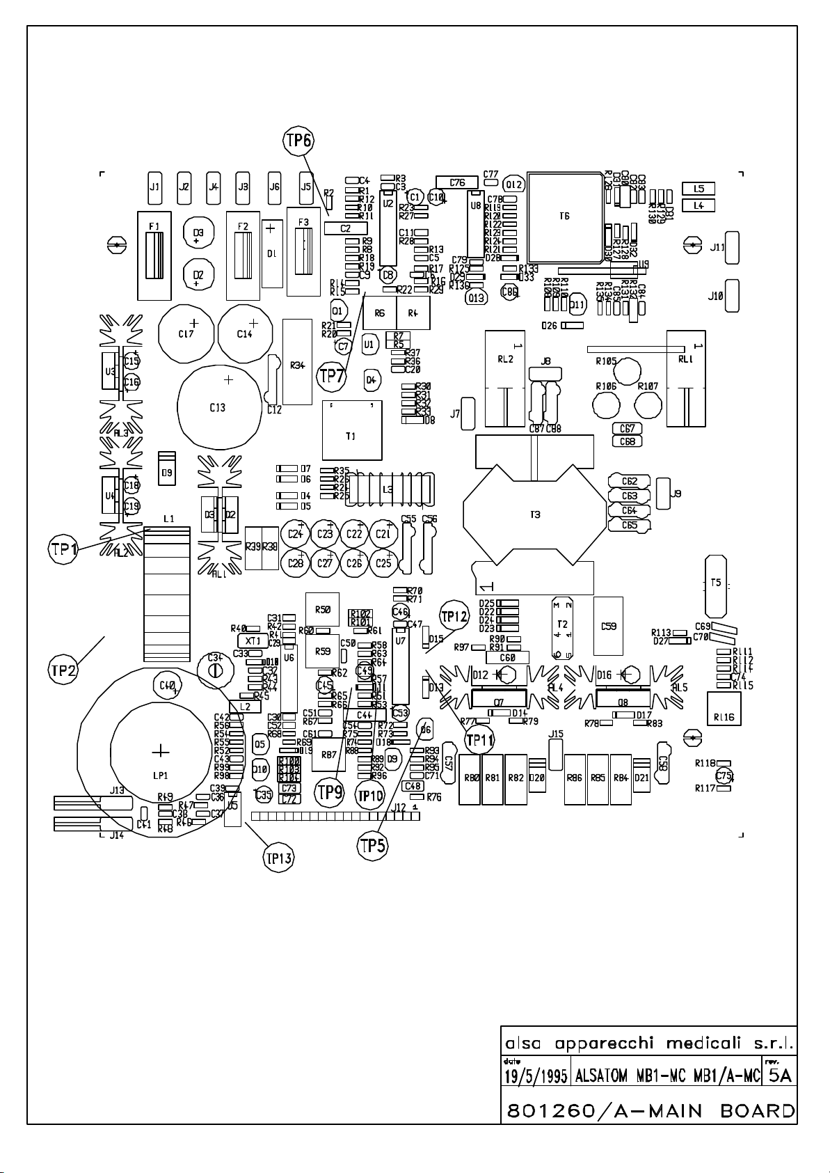
801260/a main board ..................................................................................... b
801261 MB1/A-MC microprocessor board ......................................................... c
801262 MB1-MC microprocessor board............................................................. d
.................................................................................. rev. september ’95
1
Page 2

SERVICE MANUAL
EQUIPMENT REQUIRED
DESCRIPTION FEATURES EXAMPLE
Double tracking Passband: Tektronix
oscilloscope DC - 100 MHz mod. 2235A
digital multimeter Accuracy: Hewlett Packard
DC = 1%, AC = 2% mod. E2373A
Thermoelement Passband: YOKOGAWA
10 Hz - 5 MHz mod. 2016
Digital Passband: Hewlett Packard
frequency meter 10 Hz - 100 MHz mod. HP 5384A
Voltage probe Passband: Tektronix
x 10 DC - 200 MHz mod. P6063B
Voltage probe Passband: Tektronix
x 1000 DC - 10 MHz mod. P6015
Current probe Passband: Tektronix
DC - 50 MHz mod. A6302/AM 503
A) PRELIMINARY PROCEDURE
a) remove the fuse F3 from the MAIN BOARD (board 801260-801260/a).
b) insert plug from pedal control into input port PEDAL.
c) insert neutral plate plug in its appropriate outlet MONOPOLAR.
d) insert power supply cable in current outlet.
B) LOW VOLTAGE POWER SUPPLY (board 801260-801260/a)
1) T
ESTING POWER SUPPLY VOLTAGE
+5V
AND
+15V (TP1, TP2).
a) short the R33 resistor (board 801260-801260/a). This prevents activation of the RF power generator, thus
preventing possible damage to electronic circuits that have not been tested yet.
b) set oscilloscope vertical sensivity at 1V/div. (in DC mode).
c) connect the oscilloscope probe to test point TP1.
d) turn on electrosurgical unit and make sure voltage is between 4.7V e 5.3V.
e) with oscilloscope in AC mode and sensivity set at 0.1V/div verify that ripple voltage is not over 10mVpp.
f) move oscilloscope probe on test point TP2 (Vert: 1V/div; DC) and make sure voltage is between 14.3V and
15.7V.
C) MICROCONTROLLER (board 801261-801262)
ESTING ONCE EQUIPMENT IS TURNED ON
1) T
When the electrosurgical unit is turned on, the microcontroller does automatically a selftest (about 15 seconds) to
verify anomalies of working (if present). If everything is all right, you’ll have in sequence:
- lighting of 5 green LEDs of working mode;
- lighting of power display;
- lighting of timer display (only in MB1/A-MC model);
- lighting of red LED (neutral plate alarm), yellow LED (CUT/BLEND activation) and blue LED (FORCED
COAG/SOFT COAG/BIPOLAR activation) with short acoustic signals.
After the selftest procedure, the unit shows what version of the software is being used (with a short acoustic
signal) and the display pertaining to output power shows the number '0'.
After turning on the unit, during the selftest or any other condition, the system controls and prevents possible
abnormalities shutting down output power and displaying error type with its specific code:
2
Page 3

KIND OF PROBLEM ACOUSTIC DISPLAY
SIGNAL CODE
RAM memory
(during the selftest)
1kHz 70ms ON 130ms OFF
EPROM memory
(during the selftest)
1kHz 70ms ON 130ms OFF
Supply voltage
(during the selftest)
1kHz 70ms ON 130ms OFF
RF signal modulation
(during the selftest)
1kHz 70ms ON 130ms OFF
Supply voltage
(during activation)
1kHz 70ms ON 130ms OFF
RF signal modulation
(during activation)
1kHz 70ms ON 130ms OFF
Internal variables check failure
1kHz 70ms ON 130ms OFF
Foot pedal failure
1kHz 70ms ON 130ms OFF
Neutral plate alarm
1kHz 190ms ON 190ms OFF
-
WARNING!!! AFTER TURNING ON THE ELECTROSURGICAL UNIT, IF NO LED LIGHTS, DON’T USE THE UNIT AND
CALL THE TECHNICAL SERVICE.
ALIBRATING
3) C
REF
V
VOLTAGE
a) connect the voltmeter to test point TP3 (board 801261-801262).
b) turn trimmers R57 and R61 fully clockwise (board 801261-801262).
c) set trimmer R2 (board 801261-801262) so that voltage is exactly at 4.94V.
4) T
ESTING
MODULATION SIGNAL
RF
a) connect oscilloscope probe to test point TP4 (board 801261-801262).
b) set 10W as power index in BLEND function.
c) with the electrosurgical unit turned on, test the modulation signal taking as reference the following wave-form:
Vert.: (DC) 1V/div
Hor.: 20 µs/div
e) set 10W as power index in the FORCED COAG function.
f) with the electrosurgical unit turned on, test the modulation signal, taking as reference the following wave-forms:
3
Page 4

Vert.: (DC) 1V/div
Hor.: 10 µs/div
Vert.: (DC) 1V/div
Hor.: 2 µs/div
g) set 10W as power index in the SOFT COAG function.
h) with the electrosurgical unit turned on, test the modulation signal, taking as reference the following wave-form:
Vert.: (DC) 1V/div
Hor.: 20 µs/div
4) ONE SHOT
TIMING TEST (SINGLE PULSE
)
(only for MB1/A-MC model).
a) always with oscilloscope probe on test point TP4 (board 801261-801262), set 10W as power index in the CUT
function.
b) push one time only the push-button "T" of the TIMER section. Now the timer display must show "1".
c) with the electrosurgical unit turned on, test the modulation signal, taking as reference the following wave-form:
Vert.: (DC) 1V/div
Hor.: 5 ms/div
e) verify the timing accuracy programming timer digits from 1÷99 (10ms÷0.99s).
SUPERPULSED TIMING TEST
5)
a) always with oscilloscope probe on test point TP4 (board 801261-801262) and 10W as power index in the CUT
function; push several times the push-button "T" until the digit '1' of TIMER display begins to flash.
b) verify the timing, taking as reference the following wave-form:
4
Page 5

Vert.: (DC) 1V/div
Hor.: 5 ms/div
Verify the duty-cycle is 50%.
c) push again the push-button "T" to leave the TIMER function.
d) turn off the electrosurgical unit.
e) remove jumper shorting the R33 resistor (board 801260-801260/a).
E) POWER SUPPLY (board 801260-801260/a)
ALIBRATING REFERENCE VOLTAGE VREFA
1) C
a) connect TP5 to ground. This prevents activation of the RF power generator, thus preventing possible damage to
electronic circuits that have not been tested yet.
b) insert F3 fuse.
c) set trimmer R4 at center position (board 801260-801260/a).
d) turn on electrosurgical unit and wait for the display to show '0'.
e) calibrate trimmer R6 (board 801260-801260/a) so that voltage at test point TP6 is exactly 8.0V.
ESTING POWER SUPPLY DRIVING
2) T
PWM
SIGNAL
a) connect oscilloscope probe to test point TP7 (board 801260-801260/a).
b) set 100W as power index in the CUT function.
c) activate and make sure the following wave-form appears:
Vert.: (DC) 2V/div
Hor.: 20 µs/div
ALIBRATING MINIMUM VOLTAGE
3) C
a) set 2W as power index in the CUT function.
b) make sure that, when the electrosurgical unit is not activated, voltage is lower than 3V in test point
TP8 (board 801260-801260/a).
c) press the activation pedal and bring voltage to 7V on TP8, by using trimmer R4 (board 801260-801260/a).
ALIBRATING MAXIMUM VOLTAGE
4) C
a) set 70W as power index in the FORCED COAG function.
b) press activation pedal and bring voltage to 134V on TP8, by using trimmer R6 (board 801260-801260/a).
Calibration of the two voltages, the maximum and the minimum, are interactive; thus, it is necessary to repeat
calibrations until the values that have been indicated are reached.
d) remove the jumper used to create electrical bonding on TP5 (mosfet drain Q6 board 801260-801260/a).
F) RADIOFREQUENCY (board 801260-801260/a)
a) short R33 resistor (board 801260-801260/a).
This prevents activation of the RF power generator, thus preventing possible damage to electronic circuits that
have not been tested yet.
ESTING NEUTRAL PLATE CIRCUIT
1) T
a) select CUT function.
5
Page 6

b) disconnect the two end conductors in the plate and then insert a 1000 ohm resistor in series.
c) check that red LED ALARM is turned on, at the same time that the LED turns on, a repetitive acoustic signal will
give warning of an error in the neutral plate.
d) once again, short the end conductors on the neutral plate.
ESTING WORKING FREQUENCY
2) T
a) set 10W as power index in the CUT function.
b) connect frequency meter to test point TP9 (board 801260-801260/a).
c) with the electrosurgical unit turned on, make sure that working frequency is 950 kHz (± 10kHz).
d) calibrate the trimming capacitor C24 (board 801260-801260/a) in such a way that the wave-form is the
following:
Vert.: (DC) 1V/div
Hor.: 50 ns/div
ALIBRATING THE SLOPED SIGNAL (SAW-TOOTH SIGNAL
3)C
)
a) always with the CUT function activated, regulate the R50 trimmer (board 801260-801260/a) in such a way that
the wave-form on test point TP10 will be the following:
Vert.: (DC) 1V/div
Hor.: 200 ns/div
b) turn the electrosurgical unit off.
c) remove jumper shorting the R33 resistor (board 801260-801260/a) and insert fuse F3.
ALIBRATING DEAD TIME
4) C
a) connect a load of 500 ohm to the MONOPOLAR output hook up.
b) set 10W as power index in the CUT function.
c) turn the R59 trimmer fully counterclockwise (board 801260-801260/a).
d) using both inlets of the oscilloscope, connect probe “1” to test point TP11, and probe “2” on test point TP12.
e) with the electrosurgical unit turned on, turn the R50 trimmer so that dead time (i.e. the time at which both
signals are at zero level) is equal to 250ns (board 801260-801260/a).
TP11 ADD-TP12 INVERT
Vert.: (DC) 5V/div
Hor.: 500 ns/div
6
Page 7

g) increase dead time by another 25ns by using trimmer R59 (board 801260-801260/a).
TESTING THE
5)
POWER AMPLIFIER
RF
a) set 100W as power index in the CUT function.
b) insert the RF current probe in series in the output.
c) activate the electrosurgical unit and make sure it has the following wave-form:
Vert.: (AC) 0.2A/div
Hor.: 500 ns/div
ALIBRATING CURRENT LIMITER
6) C
a) bring output load to 200 ohm.
b) set 70W as power index in the FORCED COAG function.
c) calibrate the R87 trimmer (board 801260-801260/a) in such a way that the current flowing through the output
load is 580mA.
ESTING OUTPUT POWER
7) T
a) bring the output load to 500 ohm.
b) with power set at 70W in FORCED COAG, make sure that effective current in the load is equal to 380mA
(± 5%). If necessary, it is possible to adjust the maximum output power by adjusting the R6 trimmer (board
801260-801260/a). Calibrating the R6 trimmer is allowed only if the voltage that is supplying the final stage
does not exceed 135V.
c) set 10W as power index in the CUT function.
d) make sure that the effective current in the load is equal to 140mA (± 5%). If necessary, it is possible to adjust
the maximum output power by adjusting the R4 trimmer (board 801260-801260/a).
e) set 140W as power index in the BLEND function.
f) make sure that affective current in the load is equal to 520mA (±5%).
NOTE: This manual contains a chapter (page 9) with output power curves for the electrosurgical unit; for a
complete test of the device, refer to these curves.
8) C
ALIBRATING MAXIMUM
LEAKAGE CURRENT
RF
a) bring load resistor to 1500 ohm.
b) set 150W as power index in the CUT function.
c) connect the oscilloscope probe on test point TP8.
d) by calibrating the R116 trimmer (board 801260-801260/a), find the point in which the tension displayed in the
oscilloscope decreases abruptly from 52V to 42V (± 20%).
IPOLAR COAGULATION TEST
9) B
a) connect the load in the BIPOLAR outlets.
b) bring load resistor to 100 ohm.
b) set 60W as power index in the BIPOLAR function.
c) turn on the electrosurgical unit and make sure that the effective current in the load is equal to 780mA (± 5%).
Vert.: (AC) 0.5A/div
Hor.: 500 ns/div
7
Page 8

G) CALIBRATING RF PROTECTION SYSTEMS
ROTECTION FROM MALFUNCTION CAUSED BY MODULATION SIGNAL
1) P
a) bring load resistor to 1000 ohm.
b) set 40W as power index in the FORCED COAG function.
c) with the electrosurgical unit activated, turn the R61 trimmer (board 801261-801262) slowly counterclockwise,
until the audio signal becomes intermittent and, at the same time, the RF output signal stops.
d) now turn the R61 trimmer (board 801261-801262) clockwise 15 degrees.
e) always keeping the power index at 40W, make sure that all functions are properly activated.
f) in order to simulate a malfunction condition, short the R52 resistor (board 801260-801260/a) and activate in
FORCED COAG; The audio signal must warn of a malfunction condition.
g) remove jumper shorting the R52 resistor.
2) P
ROTECTION FROM MALFUNCTION CAUSED BY POWER SUPPLY
a) bring load resistor to 500 ohm.
b) set 40W as power index in the FORCED COAG function.
c) with the electrosurgical unit activated, turn slowly the R57 trimmer counterclockwise (board 801261-801262)
until the audio sound becomes intermittent.
d) now, turn the R57 trimmer (board 801261-801262) clockwise 15 degrees.
e) always keeping the power index at 40W, make sure that all functions are properly activated.
H) CHECKING THE AUDIO SIGNAL LEVEL
The audio level has no control. The frequency and amplitude of the signal require no calibrating and are generated
directly by the microprocessor. To check, proceed as follows:
a) set 2W as power index of the CUT function.
b) connect the oscilloscope probe to test point TP13.
c) activate and make sure that the wave-form is the following:
Vert.: (AC) 2V/div
Hor.: 0.5 ms/div
I) CHECKING RF CURRENT LEAKAGE
High frequency current leakage, for insulated equipment, must never exceed 150mA RMS, as required by the CEI
EN 60601-2-2 REGULATIONS (IEC 601-2-2). The microprocessor for the electrosurgical unit MB1/A-MC has
controls allowing it to keep well below such limit. To test the efficiency of these controls, it is indispensable to
duplicate the most extreme test conditions, which in the case of the electrosurgical unit MB1/A-MC are obtained
with the CUT, BLEND, FORCED COAG and SOFT COAG at their highest power setting.
The average figures for leakage current are 110mA.
Measurement must be made as indicated by the CEI EN 60601-2-2 REGULATIONS (with insulated equipment).
8
Page 9

CURVES OF POWER CHANGES BY CHANGING THE LOADS (FROM 50 TO 2000 OHMS)
CURVES OF POWER INCREMENT (WITH NOMINAL LOAD)
9
Page 10

10
Page 11

Page 12

Page 13

Page 14
Page 15

ELECTROSURGICAL UNIT MB1A/MC - MB1/MC Revised: May 19,1995
801260/a MAIN BOARD Revision: 5A
Bill Of Materials September 25, 1995 11:38:34
Reference Part Description Cod. alsa
________________________________________________________________________
R1 330 Resistenza Strato 1/4 W 5% 430171
R2 330 Resistenza Strato 1/4 W 5% 430171
R3 3K9 Resistenza Strato 1/4 W 5% 430350
R4 10KT Trimmer Cermet 403066
R5 8K/1% Resistenza di precisione 1% 0.5W 430469
R6 2KT Trimmer Cermet 403092
R7 3K/1% Resistenza di precisione 1% 0.5W 430459
R8 10 Resistenza Strato 1/4 W 5% 430180
R9 12K Resistenza Strato 1/4 W 5% 430351
R10 330K Resistenza Strato 1/4 W 5% 430173
R11 10K Resistenza Strato 1/4 W 5% 430339
R12 150K Resistenza Strato 1/4 W 5% 430360
R13 220K Resistenza Strato 1/4 W 5% 430352
R14 100K Resistenza Strato 1/4 W 5% 430177
R15 1K Resistenza Strato 1/4 W 5% 430170
R16 27K Resistenza Strato 1/4 W 5% 430340
R17 10K Resistenza Strato 1/4 W 5% 430339
R18 100K Resistenza Strato 1/4 W 5% 430177
R19 1K Resistenza Strato 1/4 W 5% 430170
R20 100 Resistenza Strato 1/4 W 5% 430336
R21 1K Resistenza Strato 1/4 W 5% 430170
R22 47K Resistenza Strato 1/4 W 5% 430218
R23 10 Resistenza Strato 1/4 W 5% 430180
R24 56 Resistenza Strato 1/4 W 5% 430444
R25 1K Resistenza Strato 1/4 W 5% 430170
R26 56 Resistenza Strato 1/4 W 5% 430444
R27 10 Resistenza Strato 1/4 W 5% 430180
R28 10K Resistenza Strato 1/4 W 5% 430339
R29 10K Resistenza Strato 1/4 W 5% 430339
R30 22K Resistenza Strato 1/4 W 5% 430179
R31 47K Resistenza Strato 1/4 W 5% 430218
R32 4K7 Resistenza Strato 1/4 W 5% 430167
R33 10K Resistenza Strato 1/4 W 5% 430339
R34 33K/6W/F Res. 33 Kohm 6W a filo assiale 430463
R35 1K Resistenza Strato 1/4 W 5% 430170
R36 100K Resistenza Strato 1/4 W 5% 430177
R37 5K6 Resistenza Strato 1/4 W 5% 430344
R38 10K/1W Resistenza Strato 1 W 430320
R39 10K/1W Resistenza Strato 1 W 430320
R40 1K8 Resistenza Strato 1/4 W 5% 430198
R41 100 Resistenza Strato 1/4 W 5% 430336
R42 1K8 Resistenza Strato 1/4 W 5% 430198
R43 1K8 Resistenza Strato 1/4 W 5% 430198
R44 220 Resistenza Strato 1/4 W 5% 430358
R45 1K8 Resistenza Strato 1/4 W 5% 430198
R46 22K Resistenza Strato 1/4 W 5% 430179
R47 15K Resistenza Strato 1/4 W 5% 430345
R48 10K Resistenza Strato 1/4 W 5% 430339
R49 10 Resistenza Strato 1/4 W 5% 430180
R50 10KT Trimmer Cermet 403066
R51 10K Resistenza Strato 1/4 W 5% 430339
R52 4K7 Resistenza Strato 1/4 W 5% 430167
R53 47 Resistenza Strato 1/4 W 5% 430334
R54 220 Resistenza Strato 1/4 W 5% 430358
R55 10K Resistenza Strato 1/4 W 5% 430339
R56 100 Resistenza Strato 1/4 W 5% 430336
R57 1K8 Resistenza Strato 1/4 W 5% 430198
R58 220K Resistenza Strato 1/4 W 5% 430352
R59 200KT Trimmer Cermet 403104
R60 33K Resistenza Strato 1/4 W 5% 430172
R61 27K Resistenza Strato 1/4 W 5% 430340
R62 1K Resistenza Strato 1/4 W 5% 430170
R63 560 Resistenza Strato 1/4 W 5% 430178
R64 56K Resistenza Strato 1/4 W 5% 430176
R65 27K Resistenza Strato 1/4 W 5% 430340
R66 560 Resistenza Strato 1/4 W 5% 430178
R67 27K Resistenza Strato 1/4 W 5% 430340
R68 27K Resistenza Strato 1/4 W 5% 430340
R69 10K Resistenza Strato 1/4 W 5% 430339
R70 22 Resistenza Strato 1/4 W 5% 430447
R71 22 Resistenza Strato 1/4 W 5% 430447
R72 10 Resistenza Strato 1/4 W 5% 430180
R73 100K Resistenza Strato 1/4 W 5% 430177
R74 10K Resistenza Strato 1/4 W 5% 430339
R75 1K Resistenza Strato 1/4 W 5% 430170
R76 2K2 Resistenza Strato 1/4 W 5% 430343
R77 12 Resistenza Strato 1/4 W 5% 430415
R78 12 Resistenza Strato 1/4 W 5% 430415
R79 1K Resistenza Strato 1/4 W 5% 430170
R80 1K/3W/A Res. Antinduttiva 3W assiale 430450
R81 1K/3W/A Res. Antinduttiva 3W assiale 430450
R82 1K/3W/A Res. Antinduttiva 3W assiale 430450
R83 1K Resistenza Strato 1/4 W 5% 430170
R84 1K/3W/A Res. Antinduttiva 3W assiale 430450
R85 1K/3W/A Res. Antinduttiva 3W assiale 430450
R86 1K/3W/A Res. Antinduttiva 3W assiale 430450
R87 5KT Trimmer Cermet 403052
Page 16

ELECTROSURGICAL UNIT MB1A/MC - MB1/MC Revised: May 19,1995
801260/a MAIN BOARD Revision: 5A
Bill Of Materials September 25, 1995 11:38:34
Reference Part Description Cod. alsa
________________________________________________________________________
R88 1K Resistenza Strato 1/4 W 5% 430170
R89 100 Resistenza Strato 1/4 W 5% 430336
R90 470 Resistenza Strato 1/4 W 5% 430169
R91 470 Resistenza Strato 1/4 W 5% 430169
R92 4K7 Resistenza Strato 1/4 W 5% 430167
R93 47K Resistenza Strato 1/4 W 5% 430218
R94 10K Resistenza Strato 1/4 W 5% 430339
R95 10K Resistenza Strato 1/4 W 5% 430339
R96 100 Resistenza Strato 1/4 W 5% 430336
R97 2K2 Resistenza Strato 1/4 W 5% 430343
R98 470 Resistenza Strato 1/4 W 5% 430169
R99 22K Resistenza Strato 1/4 W 5% 430179
R100 2K/1% Resistenza di precisione 1% 0.5W 430461
R101 11K/1% Resistenza di precisione 1% 0.5W 430467
R102 11K/1% Resistenza di precisione 1% 0.5W 430467
R103 11K/1% Resistenza di precisione 1% 0.5W 430467
R104 33K2/1% Resistenza di precisione 1% 0.5W 430472
R105 10K/5W Resistenza Antind. 5 W 430471
R106 10K/5W Resistenza Antind. 5 W 430471
R107 10K/5W Resistenza Antind. 5 W 430471
R108 47 Resistenza Strato 1/4 W 5% 430334
R109 4K7 Resistenza Strato 1/4 W 5% 430167
R110 10K Resistenza Strato 1/4 W 5% 430339
R111 2K2 Resistenza Strato 1/4 W 5% 430343
R112 2K2 Resistenza Strato 1/4 W 5% 430343
R113 12 Resistenza Strato 1/4 W 5% 430415
R114 4K7 Resistenza Strato 1/4 W 5% 430167
R115 470 Resistenza Strato 1/4 W 5% 430169
R116 5KT Trimmer Cermet 403052
R117 100 Resistenza Strato 1/4 W 5% 430336
R118 1K Resistenza Strato 1/4 W 5% 430170
R119 220 Resistenza Strato 1/4 W 5% 430358
R120 220 Resistenza Strato 1/4 W 5% 430358
R121 22K Resistenza Strato 1/4 W 5% 430179
R122 33K Resistenza Strato 1/4 W 5% 430172
R123 100 Resistenza Strato 1/4 W 5% 430336
R124 680 Resistenza Strato 1/4 W 5% 430194
R125 180 Resistenza Strato 1/4 W 5% 430342
R126 10 Resistenza Strato 1/4 W 5% 430180
R127 470 Resistenza Strato 1/4 W 5% 430169
R128 1K5 Resistenza Strato 1/4 W 5% 430199
R129 560 Resistenza Strato 1/4 W 5% 430178
R130 820 Resistenza Strato 1/4 W 5% 430200
R131 18K Resistenza Strato 1/4 W 5% 430346
R132 10M Resistenza Strato 1/4 W 5% 430431
R133 100K Resistenza Strato 1/4 W 5% 430177
R134 2K2 Resistenza Strato 1/4 W 5% 430343
R135 1M Resistenza Strato 1/4 W 5% 430331
R136 100 Resistenza Strato 1/4 W 5% 430336
C1 10u/T/35V Cond.Tantalio 400134
C2 1n/P Cond.Poliestere 400278
C3 100n Cond.Ceramico multistrato 400139
C4 100n Cond.Ceramico multistrato 400139
C5 100p/NPO Cond.Ceramico NPO 400260
C6 220P/C Cond.Ceramico disco 400240
C7 10u/T/35V Cond.Tantalio 400134
C8 1u/T/35V Cond.Tantalio 400173
C9 22p/C Cond.Ceramico disco 400290
C10 10u/T/35V Cond.Tantalio 400134
C11 100n Cond.Ceramico multistrato 400139
C12 10n/C/1KV Cond.Ceramico disco 400133
C13 470u/E/250V Cond. Elettrolitico Verticale 400304
C14 1000u/E/35V Cond.Elettrolitico 400256
C15 10u/T/35V Cond.Tantalio 400134
C16 10u/T/35V Cond.Tantalio 400134
C17 1000u/E/35V Cond.Elettrolitico 400256
C18 10u/T/35V Cond.Tantalio 400134
C19 10u/T/35V Cond.Tantalio 400134
C20 680p/C/500V Cond.Ceramico 400292
C21 22u/E/100V/V Cond. Elett. verticale SMPS 400286
C22 22u/E/100V/V Cond. Elett. verticale SMPS 400286
C23 22u/E/100V/V Cond. Elett. verticale SMPS 400286
C24 22u/E/100V/V Cond. Elett. verticale SMPS 400286
C25 22u/E/100V/V Cond. Elett. verticale SMPS 400286
C26 22u/E/100V/V Cond. Elett. verticale SMPS 400286
C27 22u/E/100V/V Cond. Elett. verticale SMPS 400286
C28 22u/E/100V/V Cond. Elett. verticale SMPS 400286
C29 100n Cond.Ceramico multistrato 400139
C30 470p/C Cond.Ceramico disco 400242
C31 100p/NPO Cond.Ceramico NPO 400260
C32 220P/C Cond.Ceramico disco 400240
C33 12p/C Cond.Ceramico disco 400269
C34 7_100p Compensatore 7/100p 400289
C35 10u/T/35V Cond.Tantalio 400134
C36 100p/NPO Cond.Ceramico NPO 400260
C37 100n Cond.Ceramico multistrato 400139
C38 68n Cond.Ceramico multistrato 400273
C39 10n Cond.Ceramico multistrato 400251
Page 17

ELECTROSURGICAL UNIT MB1A/MC - MB1/MC Revised: May 19,1995
801260/a MAIN BOARD Revision: 5A
Bill Of Materials September 25, 1995 11:38:34
Reference Part Description Cod. alsa
________________________________________________________________________
C40 22u/E/35V Cond. Elettrolitico verticale 400237
C41 100n Cond.Ceramico multistrato 400139
C42 47p/NPO Cond.Ceramico NPO 400255
C43 100p/NPO Cond.Ceramico NPO 400260
C44 220p/PP/400V/A Cond.Polipropilene assiale 400280
C45 10u/T/35V Cond.Tantalio 400134
C46 10u/T/35V Cond.Tantalio 400134
C47 100n Cond.Ceramico multistrato 400139
C48 220n/P Cond.Poliestere metallizzato 400271
C49 10u/T/35V Cond.Tantalio 400134
C50 100n Cond.Ceramico multistrato 400139
C51 100n Cond.Ceramico multistrato 400139
C52 10n Cond.Ceramico multistrato 400251
C53 1u/T/35V Cond.Tantalio 400173
C54 100n Cond.Ceramico multistrato 400139
C55 10n/C/1KV Cond.Ceramico disco 400133
C56 10n/C/1KV Cond.Ceramico disco 400133
C57 2n2/C/3KV Cond.Ceramico disco 400223
C58 2n2/C/3KV Cond.Ceramico disco 400223
C59 220n/PP/400V Cond. Polipropilene Siemens 400297
C60 1n/P Cond.Poliestere 400278
C61 10n Cond.Ceramico multistrato 400251
C62 1n/C/3KV Cond.Ceramico disco 400224
C63 1n/C/3KV Cond.Ceramico disco 400224
C64 1n/C/3KV Cond.Ceramico disco 400224
C65 1n/C/3KV Cond.Ceramico disco 400224
C67 47p/C/6KV Cond. Ceramico disco HT 400301
C68 47p/C/6KV Cond. Ceramico disco HT 400301
C69 680p/C/500V Cond.Ceramico 400292
C70 680p/C/500V Cond.Ceramico 400292
C71 100n Cond.Ceramico multistrato 400139
C72 220n/P Cond.Poliestere metallizzato 400271
C73 220n/P Cond.Poliestere metallizzato 400271
C74 10n Cond.Ceramico multistrato 400251
C75 1u/T/35V Cond.Tantalio 400173
C76 1n/P Cond.Poliestere 400278
C77 100n Cond.Ceramico multistrato 400139
C78 100n Cond.Ceramico multistrato 400139
C79 2n2/C Cond.Ceramico disco 400261
C80 220n/P Cond.Poliestere metallizzato 400271
C81 100n Cond.Ceramico multistrato 400139
C82 100n Cond.Ceramico multistrato 400139
C83 100n Cond.Ceramico multistrato 400139
C84 100n Cond.Ceramico multistrato 400139
C85 100n Cond.Ceramico multistrato 400139
C86 10u/T/35V Cond.Tantalio 400134
C87 2n2/C/3KV Cond.Ceramico disco 400223
C88 2n2/C/3KV Cond.Ceramico disco 400223
D1 KBL06 Ponte Raddrizzatore 4A/600V 420069
D2 WL04 Ponte Raddrizzatore 1A 420013
D3 WL04 Ponte Raddrizzatore 1A 420013
D4 12V/1W Diodo Zener 12V/1W 420019
D5 12V/1W Diodo Zener 12V/1W 420019
D6 12V/1W Diodo Zener 12V/1W 420019
D7 12V/1W Diodo Zener 12V/1W 420019
D8 2V7/0.5W Diodo Zener 2V7-1/2W 420067
D9 BYT03/400 Diodo Ultra Fast 3A/400V 420071
D10 BAT83 Diodo Schottky 420070
D11 1N4148 Diodo 420010
D12 150V/5W Diodo Zener 150V/5W 420091
D13 11DQ06 Diodo Schottky 420054
D14 12V/1W Diodo Zener 12V/1W 420019
D15 11DQ06 Diodo Schottky 420054
D16 150V/5W Diodo Zener 150V/5W 420091
D17 12V/1W Diodo Zener 12V/1W 420019
D18 BAT83 Diodo Schottky 420070
D19 10V/0.5W Diodo Zener 10V-1/2W 420068
D20 BYT03/400 Diodo Ultra Fast 3A/400V 420071
D21 BYT03/400 Diodo Ultra Fast 3A/400V 420071
D22 11DQ06 Diodo Schottky 420054
D23 11DQ06 Diodo Schottky 420054
D24 11DQ06 Diodo Schottky 420054
D25 11DQ06 Diodo Schottky 420054
D26 1N4007 Diodo 420001
D27 11DQ06 Diodo Schottky 420054
D28 1N4148 Diodo 420010
D29 1N4148 Diodo 420010
D30 11DQ06 Diodo Schottky 420054
D31 10V/0.5W Diodo Zener 10V-1/2W 420068
D32 2V7/0.5W Diodo Zener 2V7-1/2W 420067
D33 1N4148 Diodo 420010
Q1 VN10KM Mosfet N 427054
Q2 IRF740 Mosfet N 427076
Q3 IRF740 Mosfet N 427076
Q4 BC237B Transistor NPN 427057
Q5 BC237B Transistor NPN 427057
Q6 VN10KM Mosfet N 427054
Q7 IRF740 Mosfet N 427076
Page 18

ELECTROSURGICAL UNIT MB1A/MC - MB1/MC Revised: May 19,1995
801260/a MAIN BOARD Revision: 5A
Bill Of Materials September 25, 1995 11:38:34
Reference Part Description Cod. alsa
________________________________________________________________________
Q8 IRF740 Mosfet N 427076
Q9 BC237B Transistor NPN 427057
Q10 VN10KM Mosfet N 427054
Q11 BC237B Transistor NPN 427057
Q12 VN10KM Mosfet N 427054
Q13 VN10KM Mosfet N 427054
L1 520uH Induttanza toroidale cod. 700 713623
L2 150uH/175mA Induttanza 422008
L3 713621 Ind. AMIDON T94-2 713621
L4 1mH/100mA Induttanza 422005
L5 1mH/100mA Induttanza 422005
U1 LM431 Regolatore 482078
U2 UC3525 PWM UC3525 482060
U3 LM78S15 Regolatore di tensione POS. +15V 482086
U4 LM7805 Regolatore LM7805 482003
U5 LM386 Amplificatore BF LM386 482056
U6 74HCT00 HCT 7400 482049
U7 UC3825 PWM UC3825 482064
U8 4093 CMOS CD4093 482025
U9 SFH600-2 Fotoaccoppiatore SFH600-2 482022
XT1 1MHZ/C Risuonatore ceramico 252002
RL1 40.52-12VDC Rele' OMRON 404040
RL2 40.52-12VDC Rele' OMRON 404040
T1 421026 Trasf. di impulsi (2 secondari) SIRIO 421026
T2 713337 Trasformatore di corrente A.F. 713337
T3 801263/A Trasf. uscita MB1/MC MB1A/MC 801263/A
T5 713708 Lettore di corrente (T68-2) 713708
T6 421025 Trasf. isolatore 10KV SIRIO 421025
F1 1A/T Fusibile 1 A T 5x20 mm 433009
F2 1A/T Fusibile 1 A T 5x20 mm 433009
F3 2A/T Fusibile 2 A T 5x20 mm 433001
J1 399028 Conn. Faston C.S. Dritto 399028
J2 399028 Conn. Faston C.S. Dritto 399028
J3 399028 Conn. Faston C.S. Dritto 399028
J4 399028 Conn. Faston C.S. Dritto 399028
J5 399028 Conn. Faston C.S. Dritto 399028
J6 399028 Conn. Faston C.S. Dritto 399028
J7 399028 Conn. Faston C.S. Dritto 399028
J8 399028 Conn. Faston C.S. Dritto 399028
J9 399028 Conn. Faston C.S. Dritto 399028
J10 399028 Conn. Faston C.S. Dritto 399028
J11 399028 Conn. Faston C.S. Dritto 399028
J12 strip_10p Strip 10 pin 446015/10
Ja12 strip_10p Strip 10 pin 446015/10
J13 399029 Conn. Faston C.S. 90 gradi 399029
J14 399029 Conn. Faston C.S. 90 gradi 399029
J15 399028 Conn. Faston C.S. Dritto 399028
LP1 449125 Altoparlante 8 ohm 0.25 W 449125
AL1 ML73_2 Dissipatore in alluminio 713249
AL2 ML73_2 Dissipatore in alluminio 713249
AL3 ML73_2 Dissipatore in alluminio 713249
AL4 ML73_2 Dissipatore in alluminio 713249
AL5 ML73_2 Dissipatore in alluminio 713249
Page 19

Page 20

Page 21

ELECTROSURGICAL UNIT MB1A/MC Revised: September 19, 1995
801261 MICROCONTROLLER SECTION Revision: 4A
Bill Of Materials September 25, 1995 14:45:56
Reference Part Description Cod. alsa
________________________________________________________________________
R1 560 Resistenza Strato 1/4 W 5% 430178
R2 5KT Trimmer Cermet 403052
R3 1K/1% Resistenza di precisione 1% 0.5W 430458
R4 3K/1% Resistenza di precisione 1% 0.5W 430459
R5 100 Resistenza Strato 1/4 W 5% 430336
R6 1K Resistenza Strato 1/4 W 5% 430170
R7 10K Resistenza Strato 1/4 W 5% 430339
R8 1K8 Resistenza Strato 1/4 W 5% 430198
R9 22K Resistenza Strato 1/4 W 5% 430179
R10 560 Resistenza Strato 1/4 W 5% 430178
R11 10K Resistenza Strato 1/4 W 5% 430339
R12 10K Resistenza Strato 1/4 W 5% 430339
R13 10K Resistenza Strato 1/4 W 5% 430339
R14 100 Resistenza Strato 1/4 W 5% 430336
R15 100 Resistenza Strato 1/4 W 5% 430336
R16 100 Resistenza Strato 1/4 W 5% 430336
R17 100 Resistenza Strato 1/4 W 5% 430336
R18 10K Resistenza Strato 1/4 W 5% 430339
R19 10K Resistenza Strato 1/4 W 5% 430339
R20 1K Resistenza Strato 1/4 W 5% 430170
R21 1K Resistenza Strato 1/4 W 5% 430170
R22 100 Resistenza Strato 1/4 W 5% 430336
R23 100 Resistenza Strato 1/4 W 5% 430336
R24 1K Resistenza Strato 1/4 W 5% 430170
R25 100 Resistenza Strato 1/4 W 5% 430336
R26 10K Resistenza Strato 1/4 W 5% 430339
R27 10K Resistenza Strato 1/4 W 5% 430339
R28 10K Resistenza Strato 1/4 W 5% 430339
R29 1K Resistenza Strato 1/4 W 5% 430170
R30 1K Resistenza Strato 1/4 W 5% 430170
R31 100 Resistenza Strato 1/4 W 5% 430336
R32 100 Resistenza Strato 1/4 W 5% 430336
R33 80/1% Resistenza di precisione 1% 0.5W 430460
R34 3K/1% Resistenza di precisione 1% 0.5W 430459
R35 80/1% Resistenza di precisione 1% 0.5W 430460
R36 10K Resistenza Strato 1/4 W 5% 430339
R37 560 Resistenza Strato 1/4 W 5% 430178
R38 22K Resistenza Strato 1/4 W 5% 430179
R39 22K Resistenza Strato 1/4 W 5% 430179
R40 22K Resistenza Strato 1/4 W 5% 430179
R41 22K Resistenza Strato 1/4 W 5% 430179
R42 22K Resistenza Strato 1/4 W 5% 430179
R43 10K Resistenza Strato 1/4 W 5% 430339
R44 1K Resistenza Strato 1/4 W 5% 430170
R46 10K Resistenza Strato 1/4 W 5% 430339
R47 10K Resistenza Strato 1/4 W 5% 430339
R48 10K Resistenza Strato 1/4 W 5% 430339
R50 10K Resistenza Strato 1/4 W 5% 430339
R51 10K Resistenza Strato 1/4 W 5% 430339
R52 1K Resistenza Strato 1/4 W 5% 430170
R53 100 Resistenza Strato 1/4 W 5% 430336
R54 10K Resistenza Strato 1/4 W 5% 430339
R55 100 Resistenza Strato 1/4 W 5% 430336
R56 1K/1% Resistenza di precisione 1% 0.5W 430458
R57 5KT Trimmer Cermet 403052
R58 1K Resistenza Strato 1/4 W 5% 430170
R59 10K Resistenza Strato 1/4 W 5% 430339
R60 1K/1% Resistenza di precisione 1% 0.5W 430458
R61 20KT Trimmer Cermet 403050
R63 1K/1% Resistenza di precisione 1% 0.5W 430458
R64 1K Resistenza Strato 1/4 W 5% 430170
R65 NU NOT USED ----- R66 22K Resistenza Strato 1/4 W 5% 430179
R67 470 Resistenza Strato 1/4 W 5% 430169
R68 470 Resistenza Strato 1/4 W 5% 430169
R69 47 Resistenza Strato 1/4 W 5% 430334
R70 47 Resistenza Strato 1/4 W 5% 430334
R72 10K Resistenza Strato 1/4 W 5% 430339
R73 10K Resistenza Strato 1/4 W 5% 430339
R74 10K Resistenza Strato 1/4 W 5% 430339
R75 10K Resistenza Strato 1/4 W 5% 430339
C1 10n Cond.Ceramico multistrato 400251
C2 47p/NPO Cond.Ceramico NPO 400255
C3 10u/T/35V Cond.Tantalio 400134
C4 100n Cond.Ceramico multistrato 400139
C5 100n Cond.Ceramico multistrato 400139
C6 100n Cond.Ceramico multistrato 400139
C7 100n Cond.Ceramico multistrato 400139
C8 100n Cond.Ceramico multistrato 400139
C9 100n Cond.Ceramico multistrato 400139
C10 10u/T/35V Cond.Tantalio 400134
C11 22p/C Cond.Ceramico disco 400290
C12 22p/C Cond.Ceramico disco 400290
C13 10u/T/35V Cond.Tantalio 400134
C14 100n Cond.Ceramico multistrato 400139
C15 10u/T/35V Cond.Tantalio 400134
C16 1N/C Cond.Ceramico disco 400252
C17 100n Cond.Ceramico multistrato 400139
Page 22

ELECTROSURGICAL UNIT MB1A/MC Revised: September 19, 1995
801261 MICROCONTROLLER SECTION Revision: 4A
Bill Of Materials September 25, 1995 14:45:56
Reference Part Description Cod. alsa
________________________________________________________________________
C18 2n2/C Cond.Ceramico disco 400261
C19 10u/T/35V Cond.Tantalio 400134
C20 100n Cond.Ceramico multistrato 400139
C21 100n Cond.Ceramico multistrato 400139
C22 100n Cond.Ceramico multistrato 400139
C23 100n Cond.Ceramico multistrato 400139
C24 47u/E/50V Cond.Elettrolitico 400296
C25 100n Cond.Ceramico multistrato 400139
C26 100n Cond.Ceramico multistrato 400139
C27 10n Cond.Ceramico multistrato 400251
C28 1u/T/35V Cond.Tantalio 400173
C29 10n Cond.Ceramico multistrato 400251
C30 100n Cond.Ceramico multistrato 400139
D1 GL5HR8 Diodo Led Rosso 5 mm 420025
D2 5V6/0.5W Diodo Zener 5V6/0.5W 420018
D3 LED_Y3 Led giallo 3mm 420079
D4 LED_Y3 Led giallo 3mm 420079
D5 LED_Y3 Led giallo 3mm 420079
D6 LED_Y3 Led giallo 3mm 420079
D7 LED_Y3 Led giallo 3mm 420079
D8 MAN6760C Display 7 Segmenti anodo comune 420060
D9 MAN6760C Display 7 Segmenti anodo comune 420060
D10 MAN6760C Display 7 Segmenti anodo comune 420060
D11 MAN6760C Display 7 Segmenti anodo comune 420060
D12 MAN6760C Display 7 Segmenti anodo comune 420060
D14 GL5HY8 Diodo Led Giallo 5 mm 420036
D15 GL5HB8 Diodo Led Blu 5 mm 420092
D16 NU NOT USED ----- D17 1N4148 Diodo 420010
D18 1N4148 Diodo 420010
Q1 BC237B Transistor NPN 427057
Q2 BC237B Transistor NPN 427057
Q3 BC237B Transistor NPN 427057
Q4 BC237B Transistor NPN 427057
Q5 BC237B Transistor NPN 427057
Q6 BC237B Transistor NPN 427057
Q7 BC307B Transistor PNP 427058
Q8 BC237B Transistor NPN 427057
Q9 BC237B Transistor NPN 427057
L1 100uH/275mA Induttanza 422006
L2 6uH8/800mA Induttanza 422007
U1 LM431 Regolatore 482078
U2 80C552 Microprocessore 482077
U3 74HC373 74HC373 482066
U4 27256 EPROM 256K 482067
U5 SAA1064 Display decoder 482080
XT1 12Mhz/HC18 Quarzo 12 Mhz 252005
SW1 MTG_1241 Pulsante da C.S. SCHURTER 416094
SW2 MTG_1241 Pulsante da C.S. SCHURTER 416094
SW3 MTG_1241 Pulsante da C.S. SCHURTER 416094
SW4 MTG_1241 Pulsante da C.S. SCHURTER 416094
SW5 MTG_1241 Pulsante da C.S. SCHURTER 416094
SW6 MTG_1241 Pulsante da C.S. SCHURTER 416094
J1 PAD_CI Capocorda realizzato su C.S. ----- J2 PAD_CI Capocorda realizzato su C.S. ----- J3 JUMP_20P Jumper 20 poli 384035+384027
J4 PAD_CI Capocorda realizzato su C.S. ----- J5 PAD_CI Capocorda realizzato su C.S. ----- J6 399028 Conn. Faston C.S. Dritto 399028
Page 23

Page 24

Page 25

ELECTROSURGICAL UNIT MB1/MC Revised: September 19,1995
801262 MICROCONTROLLER SECTION Revision: 4A
Bill Of Materials September 25, 1995 14:46:55
Reference Part Description Cod. alsa
_________________________________________________________________________
R1 560 Resistenza Strato 1/4 W 5% 430178
R2 5KT Trimmer Cermet 403052
R3 1K/1% Resistenza di precisione 1% 0.5W 430458
R4 3K/1% Resistenza di precisione 1% 0.5W 430459
R5 100 Resistenza Strato 1/4 W 5% 430336
R6 1K Resistenza Strato 1/4 W 5% 430170
R7 10K Resistenza Strato 1/4 W 5% 430339
R8 1K8 Resistenza Strato 1/4 W 5% 430198
R9 22K Resistenza Strato 1/4 W 5% 430179
R10 560 Resistenza Strato 1/4 W 5% 430178
R11 10K Resistenza Strato 1/4 W 5% 430339
R12 10K Resistenza Strato 1/4 W 5% 430339
R13 10K Resistenza Strato 1/4 W 5% 430339
R14 100 Resistenza Strato 1/4 W 5% 430336
R15 100 Resistenza Strato 1/4 W 5% 430336
R16 100 Resistenza Strato 1/4 W 5% 430336
R17 100 Resistenza Strato 1/4 W 5% 430336
R18 10K Resistenza Strato 1/4 W 5% 430339
R19 10K Resistenza Strato 1/4 W 5% 430339
R20 1K Resistenza Strato 1/4 W 5% 430170
R21 1K Resistenza Strato 1/4 W 5% 430170
R22 100 Resistenza Strato 1/4 W 5% 430336
R23 100 Resistenza Strato 1/4 W 5% 430336
R24 1K Resistenza Strato 1/4 W 5% 430170
R25 100 Resistenza Strato 1/4 W 5% 430336
R26 10K Resistenza Strato 1/4 W 5% 430339
R27 10K Resistenza Strato 1/4 W 5% 430339
R28 10K Resistenza Strato 1/4 W 5% 430339
R29 1K Resistenza Strato 1/4 W 5% 430170
R30 1K Resistenza Strato 1/4 W 5% 430170
R31 100 Resistenza Strato 1/4 W 5% 430336
R32 100 Resistenza Strato 1/4 W 5% 430336
R33 80/1% Resistenza di precisione 1% 0.5W 430460
R34 3K/1% Resistenza di precisione 1% 0.5W 430459
R35 80/1% Resistenza di precisione 1% 0.5W 430460
R36 10K Resistenza Strato 1/4 W 5% 430339
R37 560 Resistenza Strato 1/4 W 5% 430178
R38 22K Resistenza Strato 1/4 W 5% 430179
R39 22K Resistenza Strato 1/4 W 5% 430179
R40 22K Resistenza Strato 1/4 W 5% 430179
R41 22K Resistenza Strato 1/4 W 5% 430179
R42 22K Resistenza Strato 1/4 W 5% 430179
R43 10K Resistenza Strato 1/4 W 5% 430339
R44 1K Resistenza Strato 1/4 W 5% 430170
R46 10K Resistenza Strato 1/4 W 5% 430339
R47 10K Resistenza Strato 1/4 W 5% 430339
R48 10K Resistenza Strato 1/4 W 5% 430339
R50 10K Resistenza Strato 1/4 W 5% 430339
R51 10K Resistenza Strato 1/4 W 5% 430339
R52 1K Resistenza Strato 1/4 W 5% 430170
R53 100 Resistenza Strato 1/4 W 5% 430336
R54 10K Resistenza Strato 1/4 W 5% 430339
R55 100 Resistenza Strato 1/4 W 5% 430336
R56 1K/1% Resistenza di precisione 1% 0.5W 430458
R57 5KT Trimmer Cermet 403052
R58 1K Resistenza Strato 1/4 W 5% 430170
R59 10K Resistenza Strato 1/4 W 5% 430339
R60 1K/1% Resistenza di precisione 1% 0.5W 430458
R61 20KT Trimmer Cermet 403050
R63 1K/1% Resistenza di precisione 1% 0.5W 430458
R64 1K Resistenza Strato 1/4 W 5% 430170
R65 NU NOT USED ----- R66 22K Resistenza Strato 1/4 W 5% 430179
R67 470 Resistenza Strato 1/4 W 5% 430169
R68 470 Resistenza Strato 1/4 W 5% 430169
R69 47 Resistenza Strato 1/4 W 5% 430334
R70 47 Resistenza Strato 1/4 W 5% 430334
R72 10K Resistenza Strato 1/4 W 5% 430339
R73 10K Resistenza Strato 1/4 W 5% 430339
R74 10K Resistenza Strato 1/4 W 5% 430339
R75 10K Resistenza Strato 1/4 W 5% 430339
C1 10n Cond.Ceramico multistrato 400251
C2 47p/NPO Cond.Ceramico NPO 400255
C3 10u/T/35V Cond.Tantalio 400134
C4 100n Cond.Ceramico multistrato 400139
C5 100n Cond.Ceramico multistrato 400139
C6 100n Cond.Ceramico multistrato 400139
C7 100n Cond.Ceramico multistrato 400139
C8 100n Cond.Ceramico multistrato 400139
C9 100n Cond.Ceramico multistrato 400139
C10 10u/T/35V Cond.Tantalio 400134
C11 22p/C Cond.Ceramico disco 400290
C12 22p/C Cond.Ceramico disco 400290
C13 10u/T/35V Cond.Tantalio 400134
C14 100n Cond.Ceramico multistrato 400139
C15 10u/T/35V Cond.Tantalio 400134
C16 1N/C Cond.Ceramico disco 400252
C17 100n Cond.Ceramico multistrato 400139
Page 26

ELECTROSURGICAL UNIT MB1/MC Revised: September 19,1995
801262 MICROCONTROLLER SECTION Revision: 4A
Bill Of Materials September 25, 1995 14:46:55
Reference Part Description Cod. alsa
_________________________________________________________________________
C18 2n2/C Cond.Ceramico disco 400261
C19 10u/T/35V Cond.Tantalio 400134
C20 100n Cond.Ceramico multistrato 400139
C21 100n Cond.Ceramico multistrato 400139
C22 100n Cond.Ceramico multistrato 400139
C23 100n Cond.Ceramico multistrato 400139
C24 47u/E/50V Cond.Elettrolitico 400296
C25 100n Cond.Ceramico multistrato 400139
C26 100n Cond.Ceramico multistrato 400139
C27 10n Cond.Ceramico multistrato 400251
C28 1u/T/35V Cond.Tantalio 400173
C29 10n Cond.Ceramico multistrato 400251
C30 100n Cond.Ceramico multistrato 400139
D1 GL5HR8 Diodo Led Rosso 5 mm 420025
D2 5V6/0.5W Diodo Zener 5V6/0.5W 420018
D3 LED_Y3 Led giallo 3mm 420079
D4 LED_Y3 Led giallo 3mm 420079
D5 LED_Y3 Led giallo 3mm 420079
D6 LED_Y3 Led giallo 3mm 420079
D7 LED_Y3 Led giallo 3mm 420079
D8 MAN6760C Display 7 Segmenti anodo comune 420060
D9 MAN6760C Display 7 Segmenti anodo comune 420060
D10 MAN6760C Display 7 Segmenti anodo comune 420060
D14 GL5HY8 Diodo Led Giallo 5 mm 420036
D15 GL5HB8 Diodo Led Blu 5 mm 420092
Q1 BC237B Transistor NPN 427057
Q2 BC237B Transistor NPN 427057
Q3 BC237B Transistor NPN 427057
Q4 BC237B Transistor NPN 427057
Q5 BC237B Transistor NPN 427057
Q6 BC237B Transistor NPN 427057
Q7 BC307B Transistor PNP 427058
Q8 BC237B Transistor NPN 427057
Q9 BC237B Transistor NPN 427057
L1 100uH/275mA Induttanza 422006
L2 6uH8/800mA Induttanza 422007
U1 LM431 Regolatore 482078
U2 80C552 Microprocessore 482077
U3 74HC373 74HC373 482066
U4 27256 EPROM 256K 482067
U5 SAA1064 Display decoder 482080
XT1 12Mhz/HC18 Quarzo 12 Mhz 252005
SW1 MTG_1241 Pulsante da C.S. SCHURTER 416094
SW2 MTG_1241 Pulsante da C.S. SCHURTER 416094
SW3 MTG_1241 Pulsante da C.S. SCHURTER 416094
J1 PAD_CI Capocorda realizzato su C.S. ----- J2 PAD_CI Capocorda realizzato su C.S. ----- J3 JUMP_20P Jumper 20 poli 384035+384027
J4 PAD_CI Capocorda realizzato su C.S. ----- J5 PAD_CI Capocorda realizzato su C.S. ----- J6 399028 Conn. Faston C.S. Dritto 399028
 Loading...