

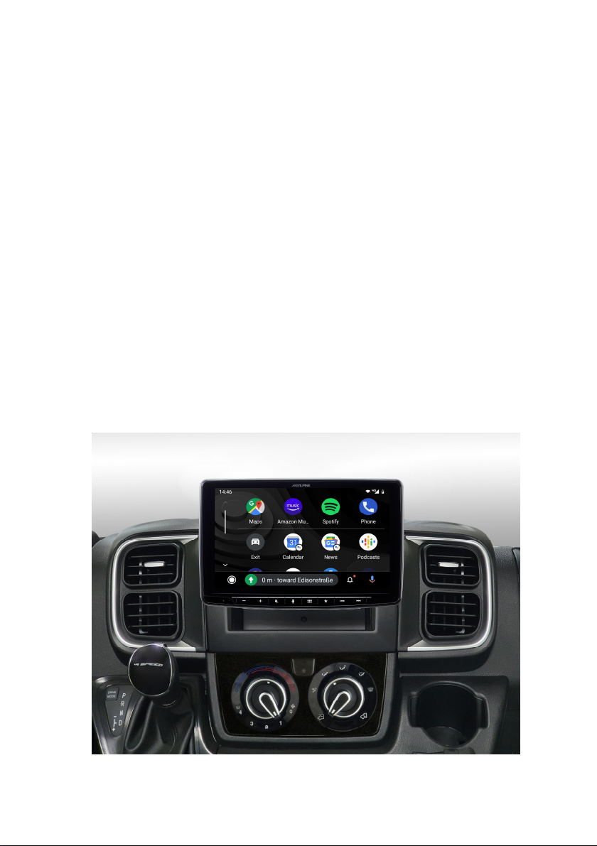
Alpine KIT-F9FI-DU8, iLX-F115DU8, iLX-F905DU8, SWRC Installation Manual
INSTALLATION MANUAL
Steering wheel remote control interface for:
FIAT
Model: Ducato III Version 8 2021
Ducato New Dash 2021
Kit content: SWRC CAN bus to UART interface with wiring
harness and ISO connector; antenna DIN adapter;
antenna FAKRA DAB
plastic socket
Compatibility: Compatible with Ducato 8 Open-Dash version
+
adapter; camera adapter;
Suitable for:
All installation work must be performed by a qualified professional installer only.
The manufacturer / dealer is not liable for any kind of incidental or indirect damages.
04/2022 ALL RIGHTS RESERVED. Technical changes possible. No liability for misprints.
INE-F904D(C) / iLX-F903D / iLX-F905D / iLX-F115D

Content and wiring harness connections
34
$
#
1
@
1 - to RADIO POWER connector
2 - to CAR connector
3 - to RADIO CONNECT2 I/F plug
4 - Green/White - SPEED output
(connect to the Alpine radio)
5 - CAMERA control/REMOTE out
6 - POWER ANTENNA output
7 - to optional/extra SERVICES:
Orange – REVERSE output
Green/White – SPEED output
8 - to external switch (Blue cable)
9 - CAN BUS connection access cable
8
0
10 - CAN BUS housing for cables
11 - ISO/DIN antenna adapter
12 - CAMERA input adapter
13 - FAKRA antenna adapter for DAB
14 - to CAR connector
ATTENTION!
Connect the connector n°15 to
the GREY connector (vehicle side),
do NOT connect it to the ORANGE
connector (vehicle side)
ATTENTION!
For vehicle with FIAT wireless Qi
charger, a separate adapter is
needed. See page 6.
7
9
5
!
6
2
+

A. Connect the CAN bus cable to vehicle (point 10 / page 2).
1. Remove the two screws of the
instrument panel cover.
2. Lift the cover at the back first
3. Now remove the cover completely
from the instrument cluster.
4. Establish a CAN bus connection to
the instrument cluster. Laying the
CAN cable from radio connector to
the back side of instrument cluster.
5. Remove the connector from the
instrument panel.
32
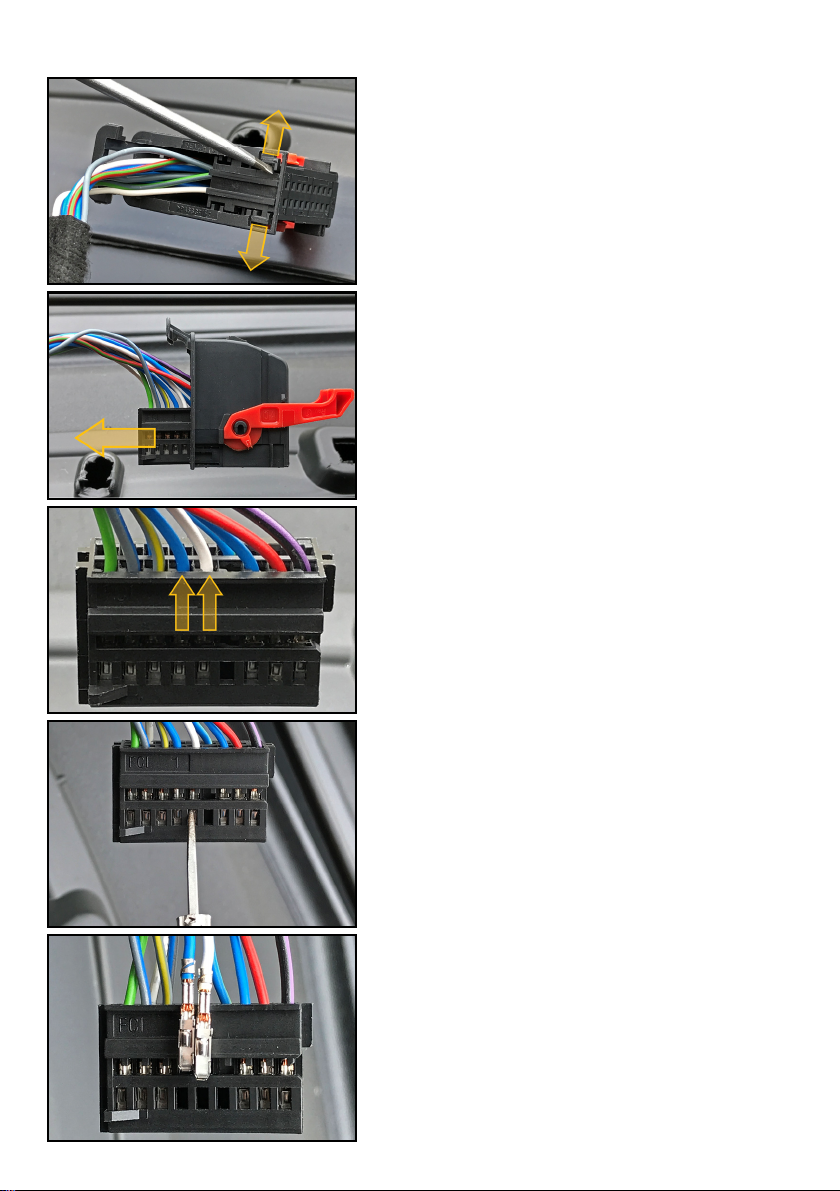
A. Connect the CAN bus cable to vehicle (point 10 / page 2).
6. Release the locking clips of the
connector housing.
7. Remove the connector from the
housing.
8. CAN cables colors:
Blue = CAN High
White = CAN Low
9. Release the terminals of the CAN
cables with the suggested release
tool.
10. Remove both cables.
 Loading...