

Page 1
SWC-D84DU
Installation Manual / Einbauanleitung
SWC-D84DU
Subwoofer
Fiat-Ducato III – Version-8/9 (2021/23>)
Optional SWA-150KIT Amplifier & Controller Kit
Page 2
SWC-D84DU
Parts list / Teileliste / Liste des pièces
1. Subwoofer Enclosure/ Tiefton Lautsprechergehäuse/ Caisson de basses
2. Metal bracket kit/ Metallhalterung Kit/ Kit de montage Subw.
3. Metal bracket extension RHD-mount/ Winkelerlängerung Rechtslenker/
4. HU adapter harness/ Radio Adapter Kabelbaum/
5. Coil-adapter subwoofer
(not needed in combination with optinal SWA-150KIT)/
Spulenadapter Tieftonlautsprecher
(nicht notwendig in Kombination mit optionalem SWA-150KIT)
Page 3
SWC-D84DU
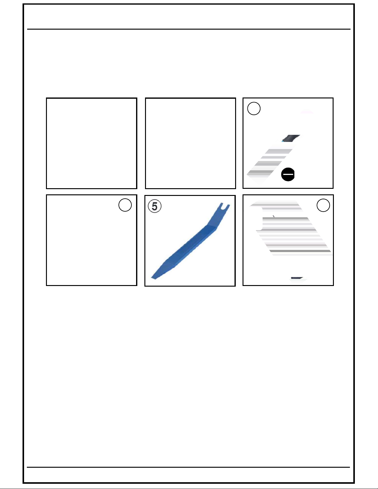
Required tools / benötigte Werkzeuge / Outil requis
3
T25T25
4
13
1. T25 Screwdriver / T25 TORX-Schraubendreher/
3
mm
6
2. PH2 Screwdriver / PH2 Kreuz-Schraubendreher/
3. 3mm slotted Screwdriver / 3mm Schlitz-Schraubendreher/
4. Ratchet + hex socket-13 / Knarre +13er Nuss / Cliquet + douille
hexagonale-13
5. Plastic Lever / Kunststoff Montagehebel / Levier en plastique
6. Pull-Out tool / Ausziehaken/
Page 4
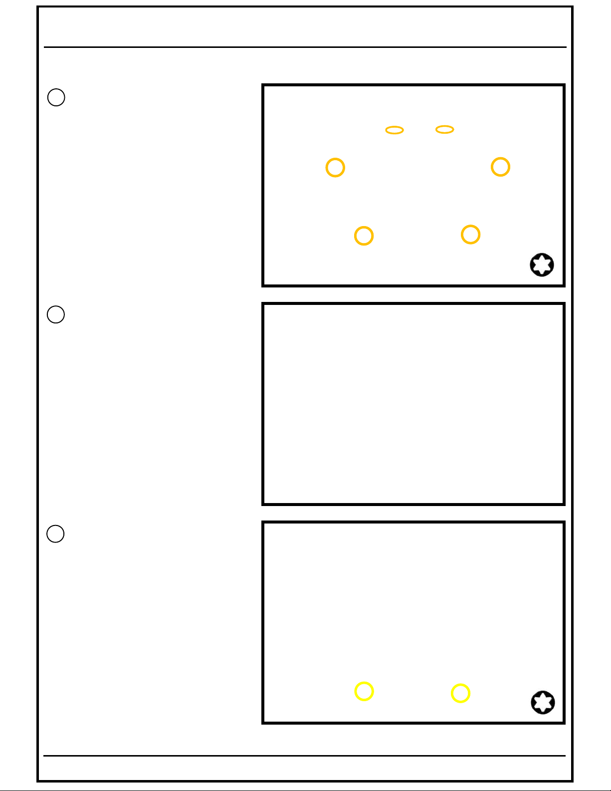
1
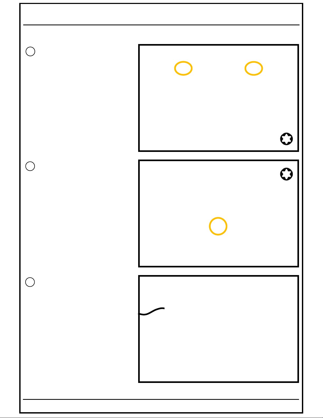
EN Remove the two round
screw covers and the T25
screws in the upper part
of the cupholder.
GE Entfernen Sie die beiden
runden Schraubenabdeckungen sowie die T25
Torx Schrauben aus dem
oberen Teil des
Getränkehalters.
2
SWC-D84DU
EN Remove the rubber layer
from the cupholder
and the T25 screw.
GE Entnehmen Sie die
Gummieinlage aus dem
Getränkehalter und die
darunter sitzende T25
Torx Schraube.
3
EN Pull out the whole
cupholder part
(In case there is a USB-jack
remove it in advance).
GE Ziehe die komplette
Getränkehaltereinheit ab
(Sollte eine USB-Buchse
vorhanden sein, entferne
diese zuvor).
Page 5
SWC-D84DU
4
EN Remove the six T25 screws.
GE Entfernen Sie die sechs
T25 Torx Schrauben.
5
EN Remove the center console
plastic bracket.
GE Entfernen Sie den
Mittelkonsolen-Träger.
6
EN Remove the two T25 screws
from the lower plastic panel.
GE Entfernen Sie die zwei
T25 Torx Schrauben aus der
unteren Abdeckung.
Page 6
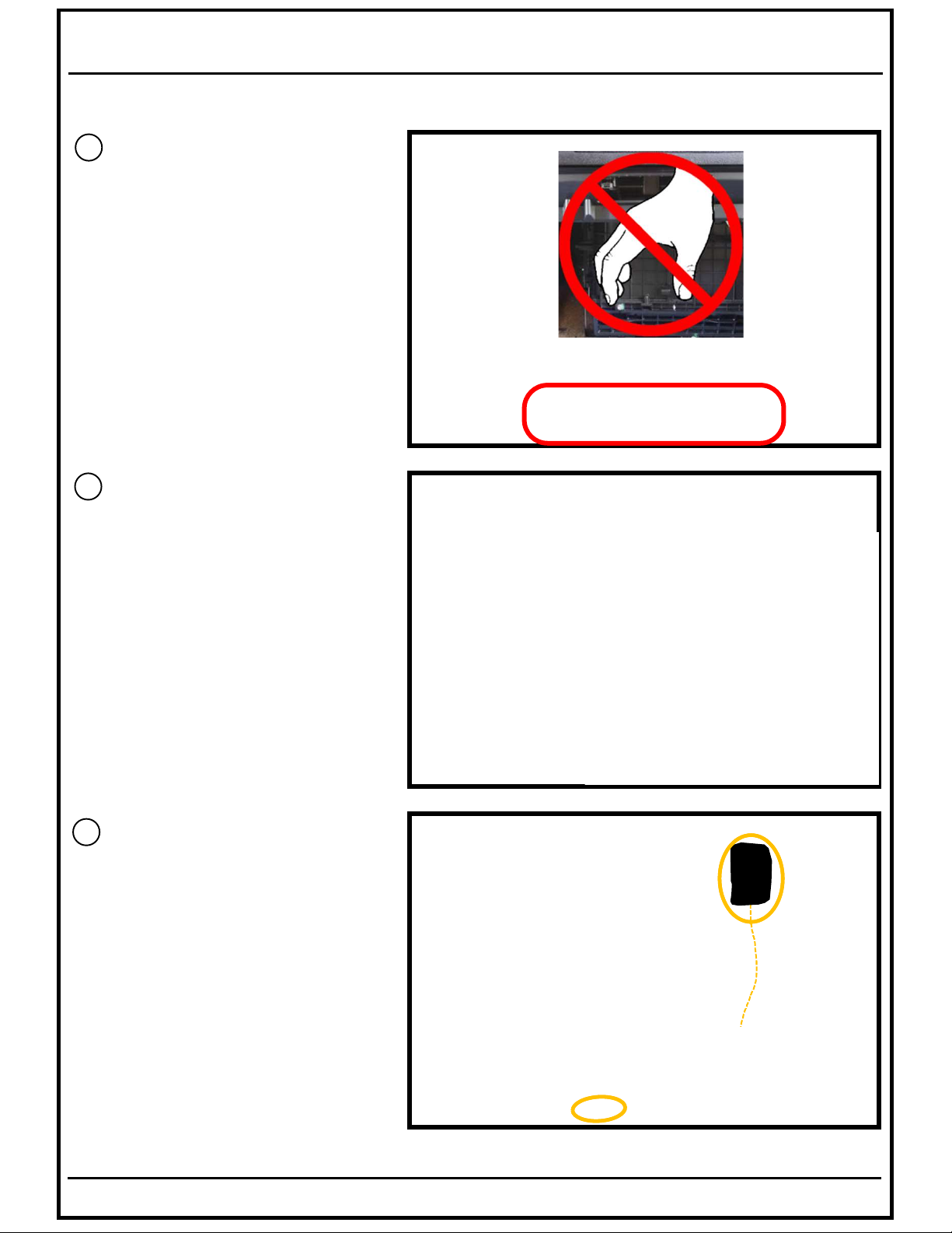
7
EN Don‘t remove the lower
plastic panel because here
the metal bracket of the
SWC-D84S will be fixed.
GE Die untere Abdeckung
verbleibt in der originalen
Position und darf nicht entfernt
werden, da hier der Metallhalter des SWC-D84DU
angebracht wird.
8
SWC-D84DU
EN Remove the right air vent
with a pull-out tool.
GE Entnehmen Sie den rechten
Luftausströmer mit einem
Ausziehhaken.
9
EN Insert the headunit adapter
harness between the radio
and the lower center console.
GE Verlegen Sie den
mitgelieferten Adapter
Kabelbaum zwischen
Radio und der unteren
Mittelkonsole.
Page 7
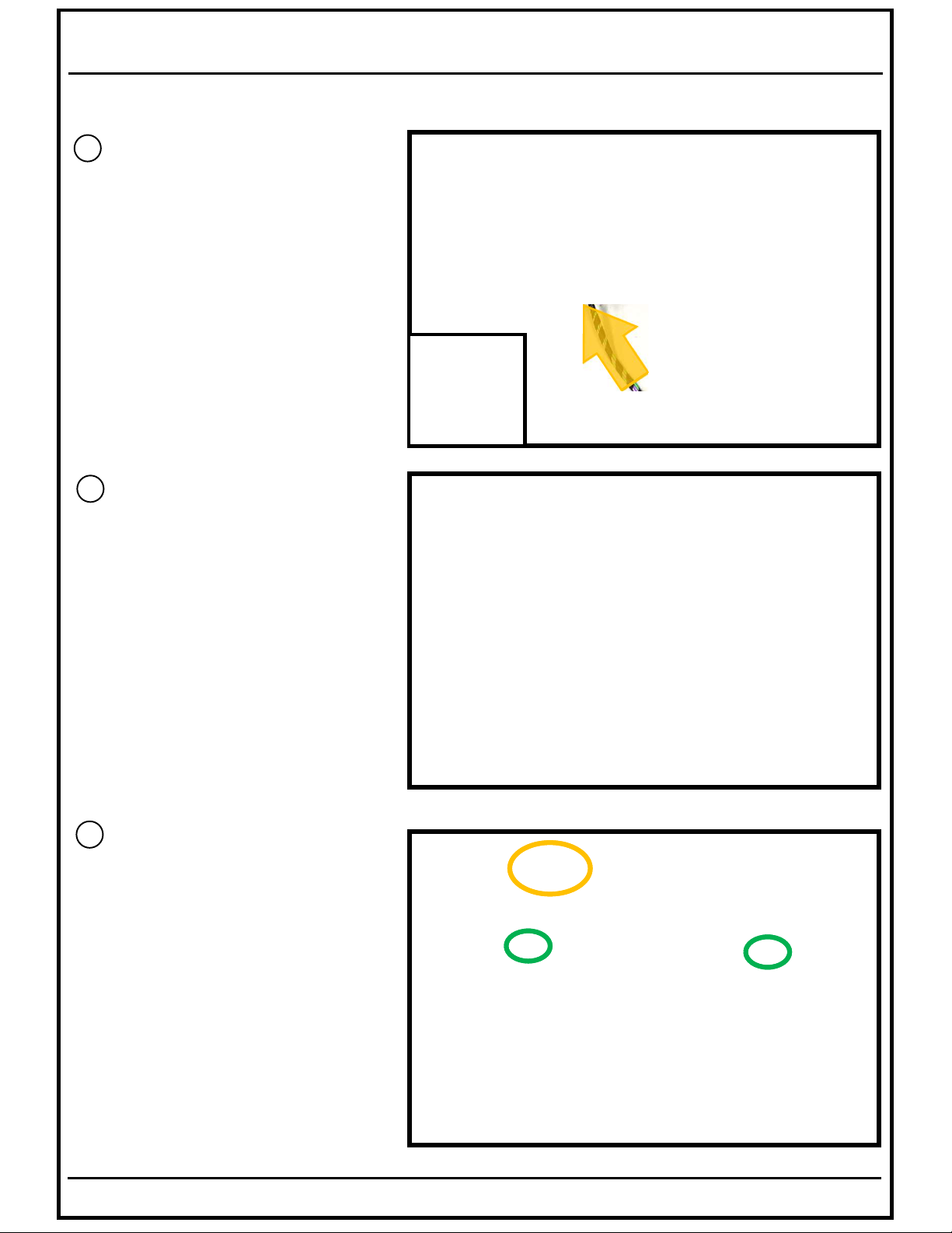
10
EN Take the metal bracket of
the subwoofer enclosure and
insert the cable of the subw.
coil-adapter throuw the hole
inside the bracket.
GE Nehmen Sie die Metall-
halterung für das Tieftongehäuse zur Hand und
führen Sie das Kabel des
Spulenadapters durch die
Kabelöffnung hindurch.
11
SWC-D84DU
EN Fix the subw. coil-adapter
with the two cable ties to the
provided holes inside the
subwoofer metal bracket.
GE Befestigen Sie den
Spulenadapter mit den zwei
mitgelieferten Kabelbindern
an den dafür vorgesehenen
Löchern in den Metallhalter.
12
EN Fix the metal bracket with the
two screws to the lower cover
and connect the cable from
the headunit harness to the
coil adapter connector.
GE Schrauben Sie die Metall-
halterung mit den zwei
unteren Schrauben an die
untere Abdeckung an und
verbinden Sie den Stecker
des Radio Adapter Kabels
mit dem Spulenadapter.
Page 8
SWC-D84DU
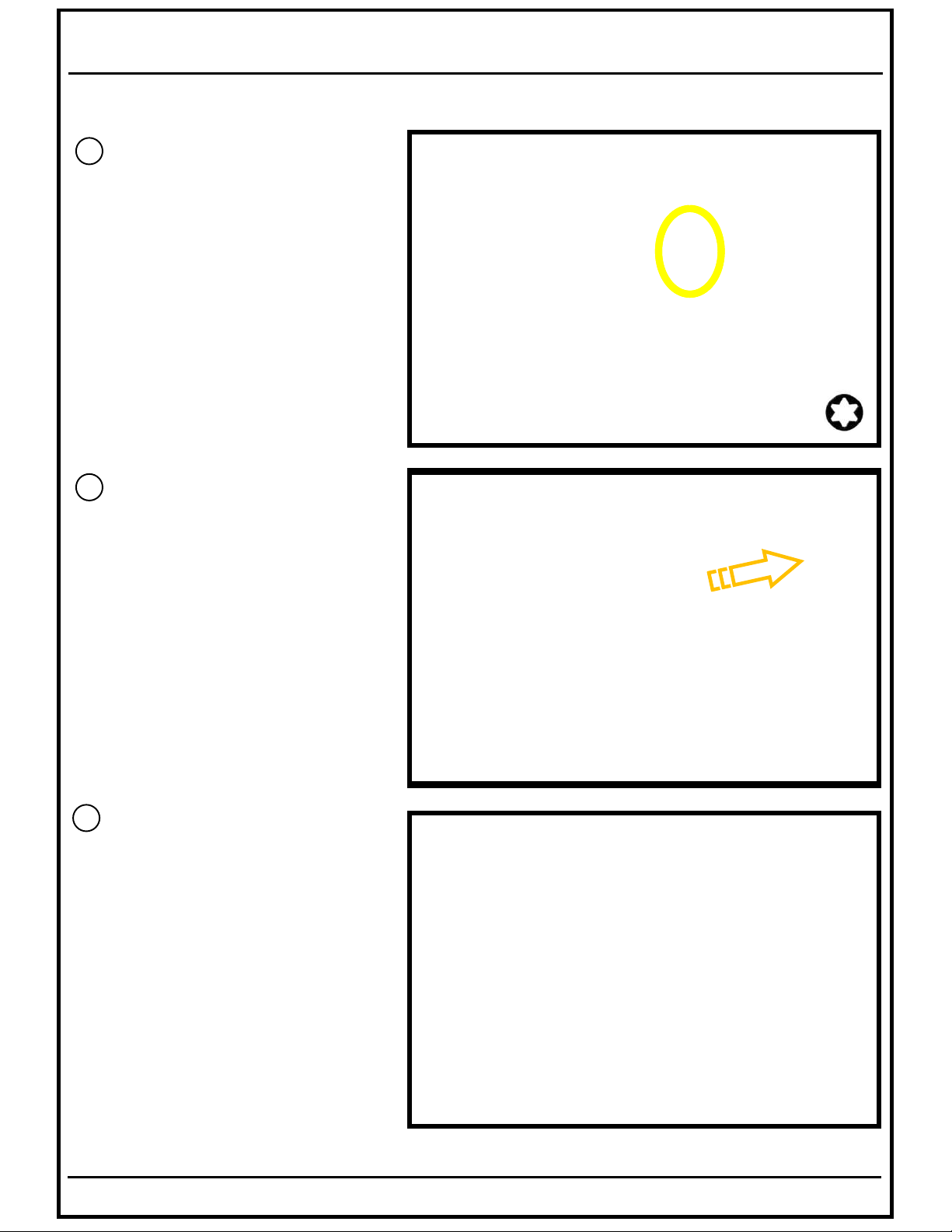
13
EN Use the two original screws
to fix the metal bracket and
the lower palstic cover.
GE Verwenden Sie hierzu wieder
die zwei Original Schrauben
der Abdeckung.
14
EN To reach the above screws
more easy plaease move
the lower plastic cover to
the front.
GE Um besser an die oben
beschriebenen Schrauben zu
gelangen, drücken Sie die
untere Verkleidung leicht
nach vorne.
15
EN Insert the center console
plastic bracket.
GE Setzen Sie den Mittel-
Konsolenträger wieder ein.
L R
Page 9
SWC-D84DU
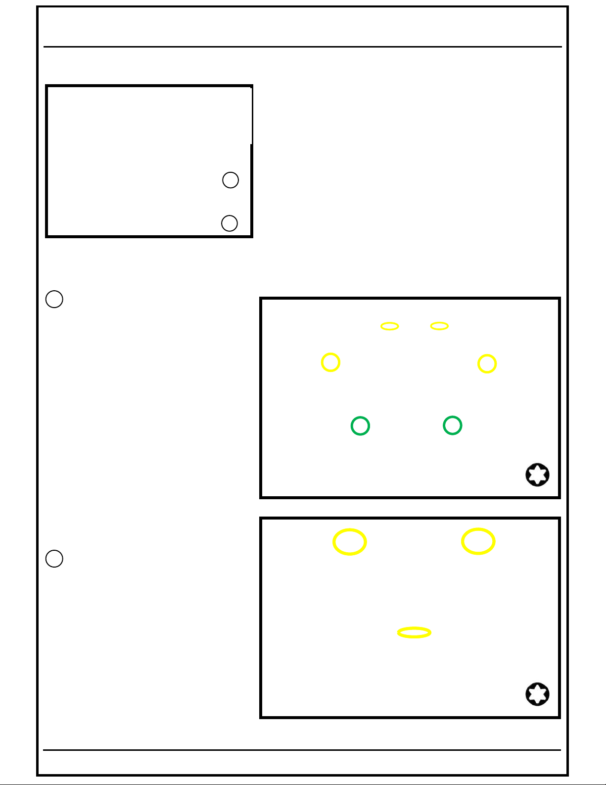
EN In case you‘ll install also the
SWA-150KIT please proceed
first with installation step
GE Wenn auch das SWA-150KIT
verbaut wird, folgen Sie bitte
zuerst den Einbauschritt
16
EN Fix the center console plastic
bracket with the six T25
screws. The two lower screws
will fix lso the bracket of the
subwoofer enclosure.
GE Verschrauben Sie den Mittel-
konsolenträger mit den sechs
T25 Torxschrauben.
Die zwei unteren Schrauben
befestigen zugleich auch die
Metall-Halterung des
Lautsprecher-Gehäuses.
26
26
17
EN Fix the cup holder with the
three T25 screws and insert
the rubber inlay.
GE Befestigen Sie den Getränke-
halter mit den drei T25 Torx
Schrauben und fügen legen
die Gummieinlage wieder ein.
Page 10
SWC-D84DU
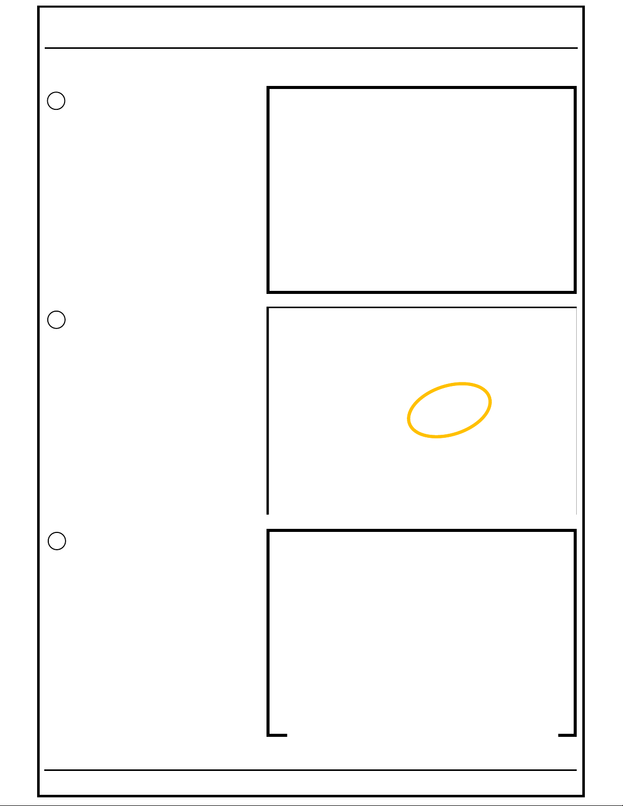
18
EN Subwoofer enclosure
GE Tiefton-Lautsprechergehäuse
19
EN Connect the speaker cable
which you passed through
the hole inside the metal
bracket before.
GE Schließen Sie das
Lautsprecherkabel an, dass
Sie zuvor durch die Metallhalterung durchgeführt haben.
20
EN Bring the enclosure into the
position in front of the
metal bracket.
GE Positionieren Sie das
Lautsprechergehäuse vor
der Metallhalterung.
Page 11
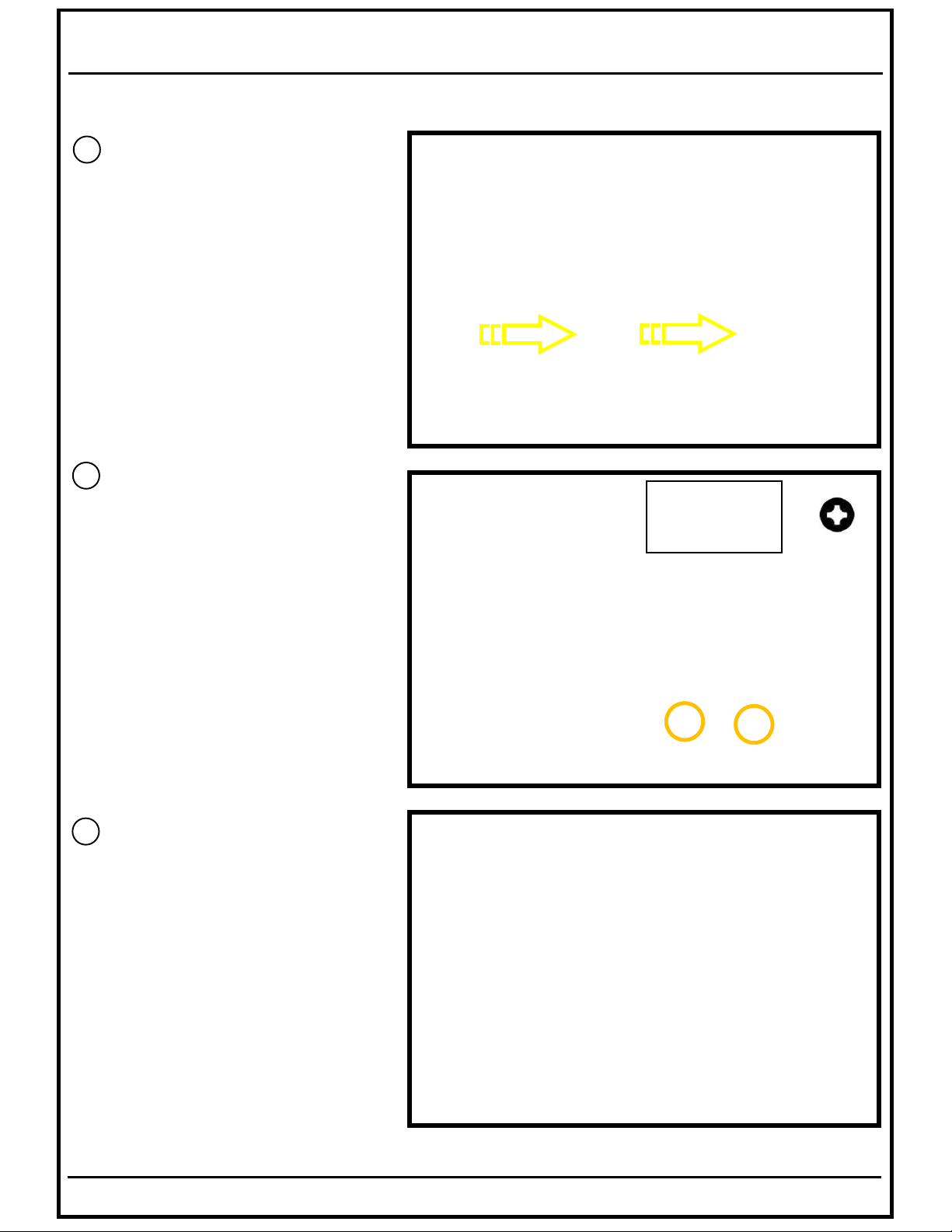
21
EN Shift the enclosure into the
metal bracket.
Be carefule with the speaker
cable to avoid to squeeze it!
GE Schieben Sie das
Lautsprechergehäuse in die
Metallhalterung.
Passen Sie dabei auf, dass
Lautsprecherkabel nicht
abzuquetschen!
22
SWC-D84DU
EN Fix the enclosure with the
four attached screws.
Two on each side.
Take care about the
different screw sizes!
GE Schrauben Sie die vier
mitgelieferten Schrauben,
zwei pro Seite, ein um das
Gehäuse zu befestigen.
Achten Sie dabei auf die
Größenunterschiede der
Schrauben.
23
EN The installation of the
subwoofer enclosure is
compleated!
GE Der Einbau des
Lautsprechergehäuses
ist abgeschlossen.
Page 12
SWC-D84DU
EN Needed installation steps when the radial front speakers SPC-R100-DU are installed
GE Notwendige Installationsschritte bei Verbau der Radial Frontlautsprecher SPC-R100-DU
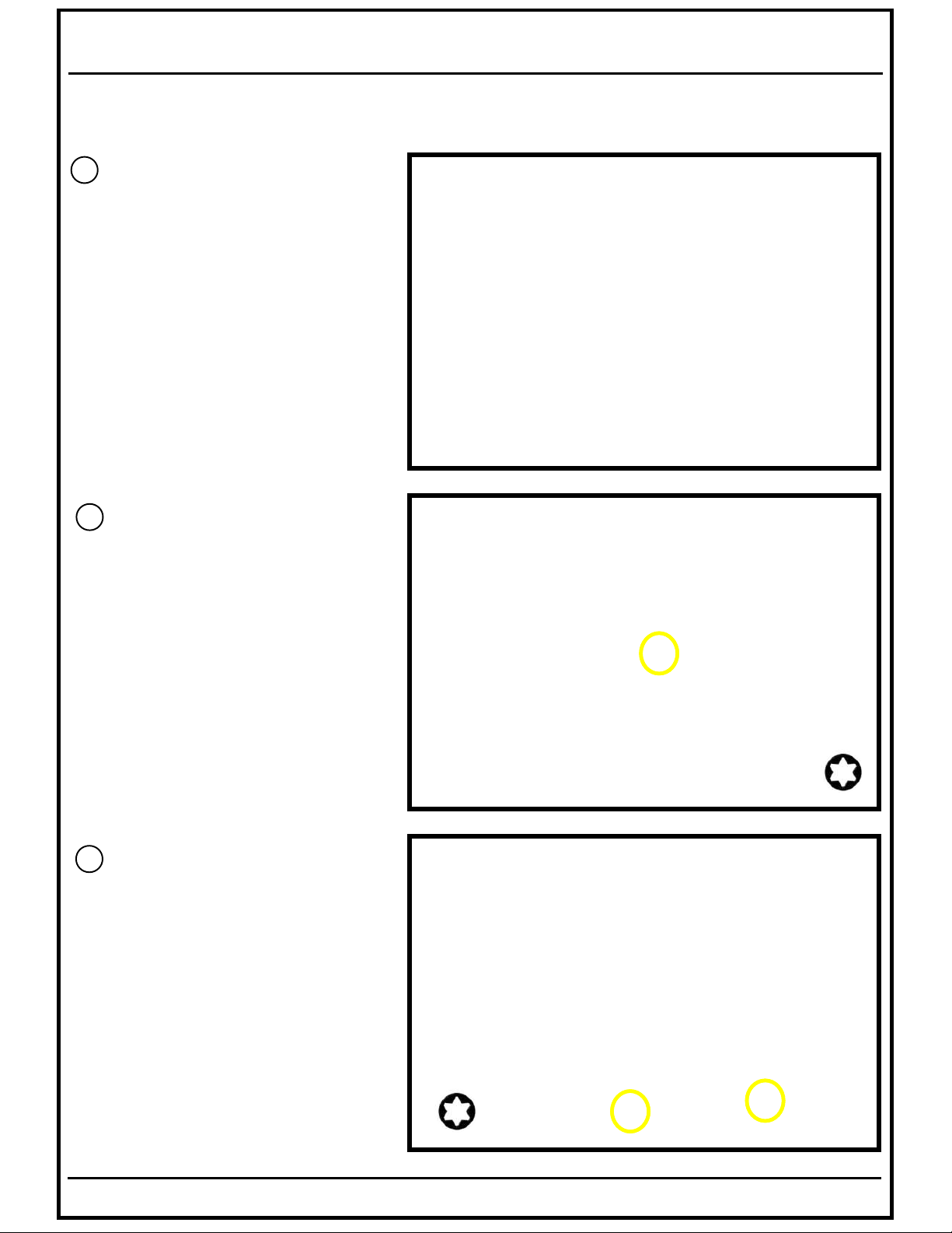
24
EN Before you start the operation,
you’ve to disconnect the original
Ducato door speaker.
Please remove as described the
door panel.
GE Bevor Sie das System in Betrieb
nehmen, müssen Sie noch die
originalen Ducato
Türlautsprecher abklemmen.
Entfernen Sie dazu wie
beschrieben die Türverkleidung.
25
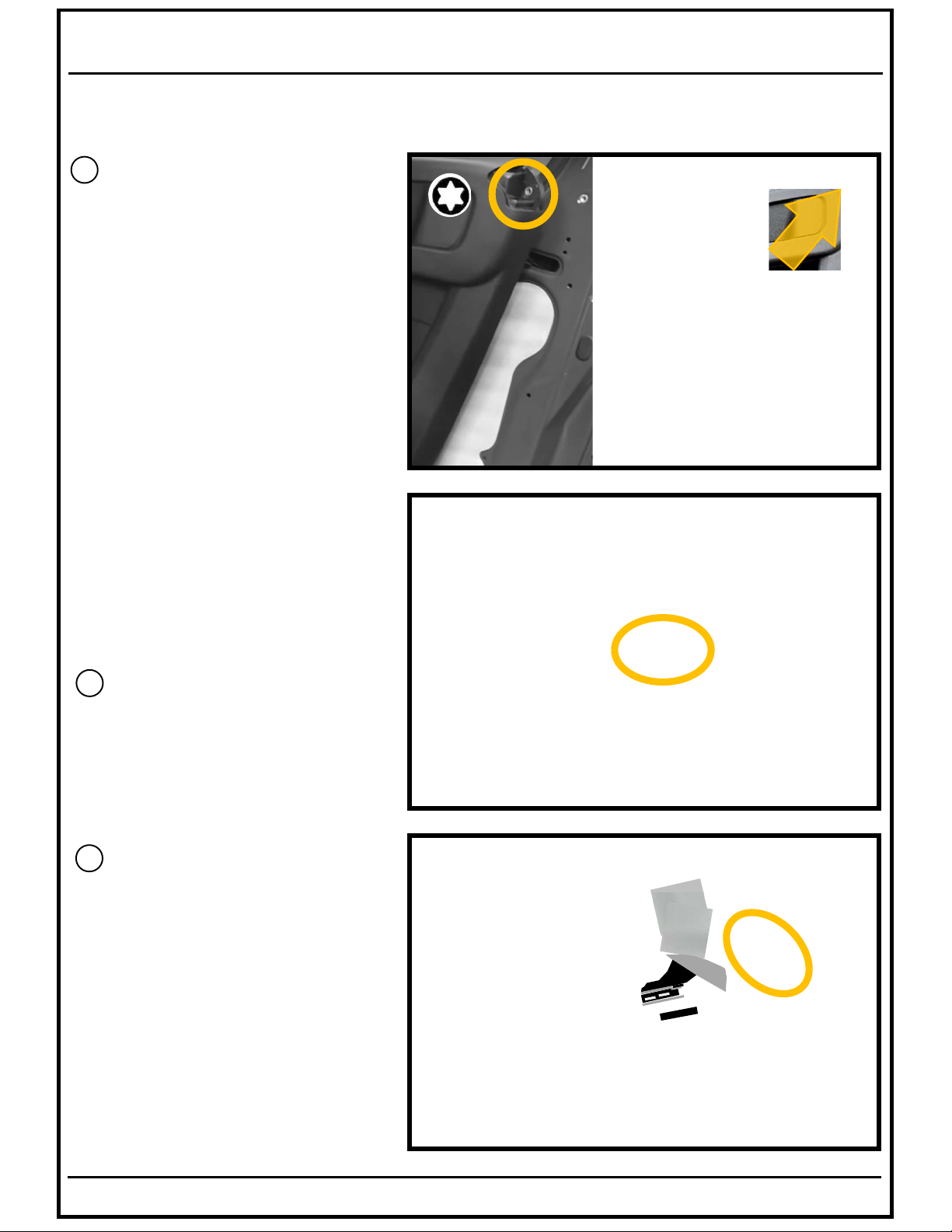
EN Remove the inlay and the T25
screw of the top door handle.
GE Entnehmen Sie die Einlage
sowie die T25 Torxschraube des
oberen Türgriffs..
26
EN Remove the two Torx screws
(T25) from the bottom of the
door panel.
GE Entfernen Sie die beiden Torx-
schrauben (T25) an der
Unterseite der Türverkleidung.
Page 13
SWC-D84DU
EN Needed installation steps when the radial front speakers SPC-R100-DU are installed
GE Notwendige Installationsschritte bei Verbau der Radial Frontlautsprecher SPC-R100-DU
27
EN Remove the screw cover and
the Torx screw (T25) in the lower
door panel.
GE Entfernen Sie die
Schraubenabdeckung und die
Torx Schraube (T25) der unteren
Türverkleidung.
28
EN Remove carefully the cover inside
the door handle and remove the
Torx screw (T25) behind.
GE Entfernen Sie die Abdeckung
hinter dem Türgriff sowie die Torx
Schraube (T25) dahinter.
29
EN Lift up and unlock carefully the
electrical switch panel with a
plastic lever, unplug the electrical
panel and remove the Torx screw
(T25) behind the switch panel.
GE Entriegeln Sie vorsichtig mit
einem Kunststoffhebel die
elektrische Schaltergruppe, lösen
Sie den Stecker und entfernen
Sie die Torxschraube (T25).
Page 14
SWC-D84DU
EN Needed installation steps when the radial front speakers SPC-R100-DU are installed
GE Notwendige Installationsschritte bei Verbau der Radial Frontlautsprecher SPC-R100-DU
30
EN Remove the Torx screw (T25) in
the right corner of the door panel.
In case this screw is covered by
the frame of a window blind just
unlock the door panel clips and
lift up the door panel to get
access to the speaker connector.
GE Entfernen Sie die Torx Schraube
(T25) in der oberen Ecke der
Türverkleidung. Sollte diese
Schraube durch den Rahmen
einer Verdunkelungsjalousie
verdeckt sein, lösen Sie lediglich
die Türverkleidung soweit um and
den Stecker des Lautsprechers
zu gelangen.
31
EN Unplug the connector from the
speaker.
GE Ziehen Sie den Stecker vom
Lautsprecher ab.
32
EN Store the speaker connector
in this area beside and fix it
with tape.
GE Verstauen Sie den Stecker
neben der Lautsprecheraufnahme und befestigen Sie
ihn mit Klebeband.
Page 15
SWC-D84DU
EN Needed installation steps when the amplifier & controller kit SWA-150KIT is installed
GE Notwendige Installationsschritte bei Verbau des Verstärker & Controller Sets SWA-150KIT
33
SWA-150KIT
EN Amplifier & Controller Kit.
GE Verstärker & Controller Set
34
EN Open the vehicle battery
compartment in front of the
driver seat by unlock the six
plastic screws.
GE Öffnen Sie das Batteriefach
vor dem Fahrersitz durch
Entriegelung der sechs
Plastikverschlüssen.
35
EN Insert the amplifier power
cables (+/-) into the battery
compartment.
GE Verlegen Sie das Plus- und
Minuskabel des Verstärkeranschlußkabels bis in den
Batteriekasten.
Page 16
36
EN Connect the red (+) cable
to the plus terminal of the
vehicle battery.
GE Schließen Sie das rote (+)
Kabel an den Pluspol der
Fahrzeugbatterie an.
37
SWC-D84DU
EN Connect the black (-) cable
to the GND-terminal of the
vehicle battery.
GE Schließen Sie das schwarze
(-) Kabel an den Massepol
der Fahrzeugbatterie an.
38
EN Stick the amplifier with the
included self-adhesive
Velcro pads to the plastic
center console bracket.
GE Kleben Sie den Verstärker
mit den mitgelieferten
Klettklebepads an den
Konsolenträger an.
Page 17
SWC-D84DU
39
EN Pass the powercable from
the battery compartment to
the amplifier location in the
center console bracket.
GE Verlegen Sie das Verstärker-
anschlußkabel vom
Batteriefach zum Verstärker
auf dem Konsolenträger.
40
EN Stick the controller with the
self-adhesive Velcro pads
at the provided position and
pass the cable to the
amplifier.
GE Kleben Sie den Controller mit
dem beiliegenden Klettklebepad an die vorgesehene
Position und führen das
Kabel zum Verstärker.
41
EN Pass the speaker cable
behind the center console
bracket to the already
installed headunit adapter
cable and insert the
connectors.
GE Führen Sie die Lautsprecher-
anschlußleitung hinter die
Konsole bis zum Anschluß
des bereits verlegten Radio
Adapter Kabels und
verbinden Sie die Stecker.
+/-
Subwoofer Tieftonlautspr.
Page 18
SWC-D84DU
EN Don’t use the coil-adapter of the SWC-D84DU in combination with the SWA-150KIT
GE Verwenden Sie nicht den Spulenadapter des SWC-D84DU in Kombination mit SWA-150KIT
“Cresendo Ensemble” System: SWC-D84DU (+ SPC-R100DU)
Coil-adapter subwoofer/
Spulenadapter Tieftonlautspr.
SWC-D84DU
“Concert Ensemble” System: SWC-D84DU + SWA-150KIT (+ SPC-R100DU)
SWC-D84DU
SWA-150KIT
Page 19

SWC-D84DU
EN In case you’ll combine the “ALPINE Crescendo or Concert Ensemble” Soundsystem with one of the
below listed ALPINE Multimedia Systems you can increase the sound performance by the right
setup of your DSP parameter (follow the settings listed in below table)
GE Falls Sie ihr “ALPINE Crescendo or Concert Ensemble” Soundsystem mit einer unten aufgelisteten
Multimedia Einheit kombinieren, können sie den Klang durch die richtige Einstellung der DSP
Parameter abermals optimieren (folgen Sie dazu den Einstellungen in der unten stehenden Tabelle)
Page 20

SWC-D84DU
EN The cupholder center console is mandatory for the installation of the Subwoofer Enclosure!
In case your vehicle isn’t equipped with this cupholder please order the part from your FIAT dealer.
GE Die Mittelkonsole mit Getränkehalter ist eine Grundvorraussetzung um das Subwoofergehäuse zu
installieren. Sollte ihr Fahrzeug nicht mit dieser Konsole ausgestattet sein können Sie diese bei
ihrem FIAT Händler als Ersatzteil bestellen.
Cupholder Center Console
(FIAT Part-No.: 735703629)
ALPS ALPINE EUROPE GmbH
Ohmstrasse 4
85716 Unterschleißheim
Germany
Ver.1.0 (Mar.2024)
 Loading...