

Page 1
MANUAL
®
Alpha
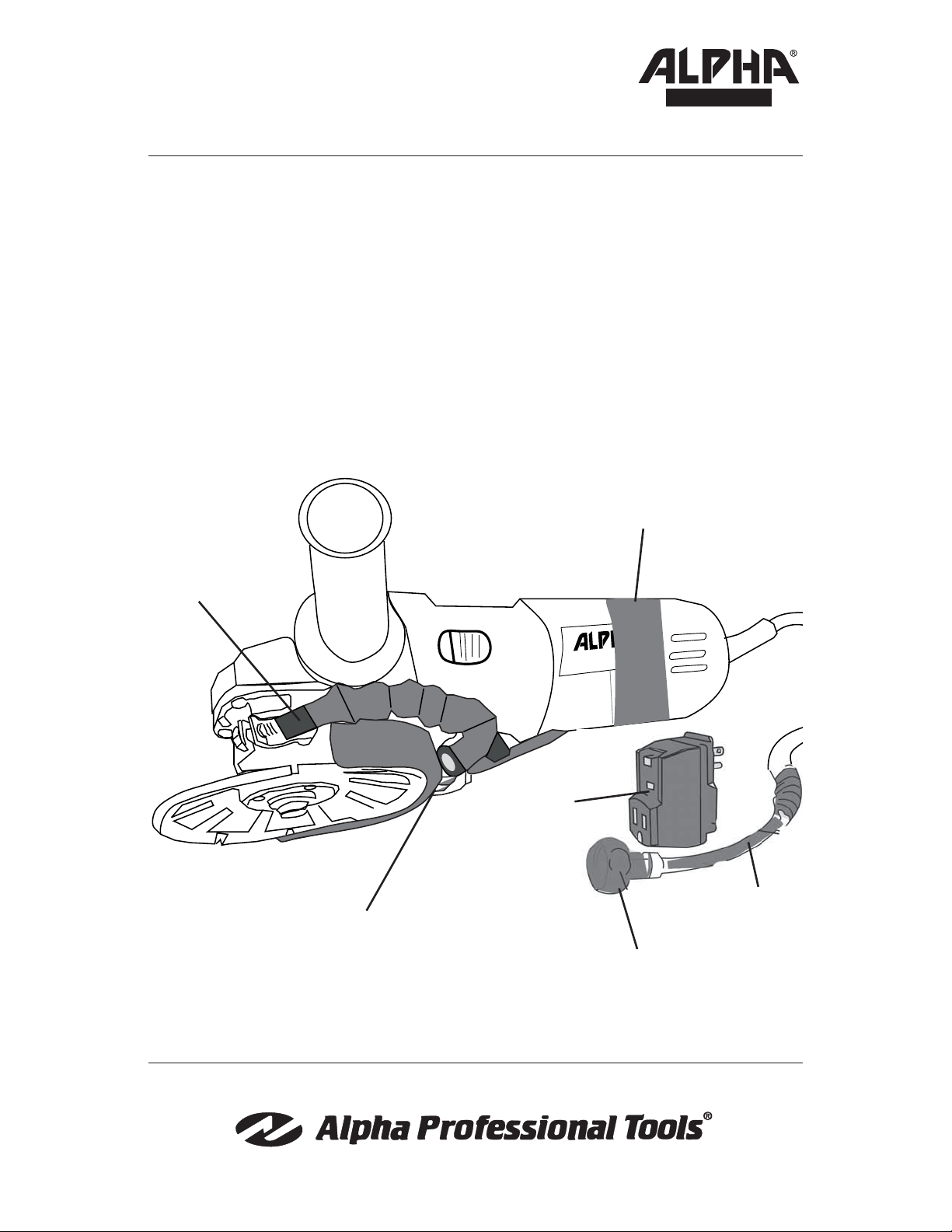
Wet Blade
Cutting Kit
Instruction Manual
Hook & Loop Strap
Coolant Tube
Blade Guard
*Tool and Blade sold separately
®
HSG-125
GFCI
Water Line
Garden Hose Adapter
Part No: WBCKIT
103 Bauer Drive, Oakland, NJ 07436 • 800-648-7229 • Fax: 800-286-0114
www.alpha-tools.com
Page 2
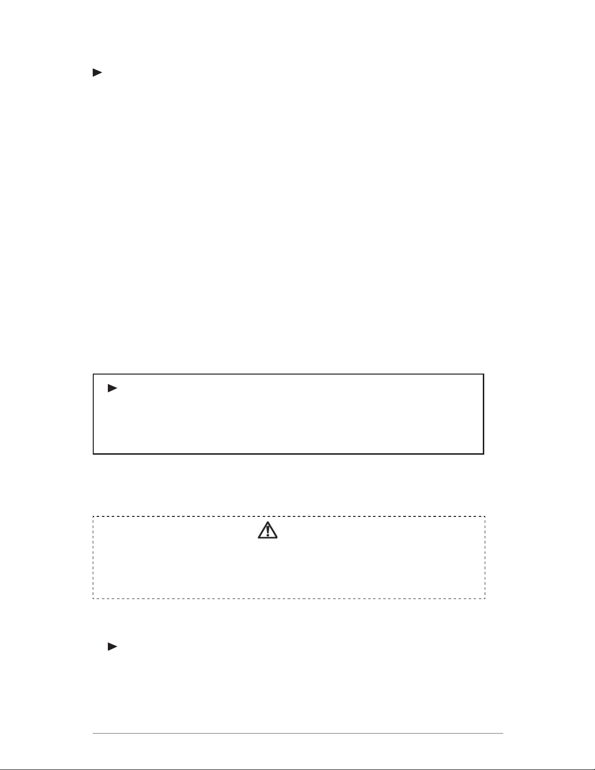
TABLE OF CONTENTS
CONTENTS
Parts List .............................................................................................. 3
Instructions ........................................................................................... 3
Creating Thread Holes for the Protective Guard .................................. 4
Assembly of WBCKIT Guard ................................................................ 4
Installation of WBCKIT Guard .............................................................. 5
Garden Hose Adapter Installation ........................................................ 6
Installation of Plastic Wire Wrap ........................................................... 7
Installation of GFCI ............................................................................... 7
Completed Assembly ............................................................................ 7
SERVICE
Use only Alpha Professional Tools® accessories and spare parts. Should
components which have been described need to be exchanged, please contact
your dealer or Alpha Professional Tools®.
CAUTION!
• Attach the Wet Blade Cutting Kit correctly by following the procedure in this
instructional manual.
• During operation, be sure to wear personal safety equipment.
NEED MORE INFORMATION
For information on Alpha Professional Tools® complete product line, visit us on the
web at www.alpha-tools.com.
2
Page 3
PARTS LIST
4
9
1
2
3
6
5
7
8
No. Item Description Part Number
1. Protective Guard for HSG-125
The WBCKIT can also be attached to
other grinders with minimal alteration
to their safety guards
2. Water Line (10’) 3m*
3. Garden Hose Adapter*
4. Ground Fault Circuit Interrupter GFCI-1
5. Hook & Loop Strap 140003
6. Coolant Tube 140004
7. 90 degree Swivel Fitting 140005
8. Plastic Ties PDH-CABLETIES
9. Plastic Wire Wrap 140002
* Not sold separately.
INSTRUCTIONS
140007
133287
Alpha Professional Tools® provides the highest quality parts and manufacturing techniques
in the manufacture of this product. In order to obtain the maximum effectiveness and
provide the highest degree of safety, it is necessary to review and follow these instructions
carefully before using the tool.
3
Page 4

CREATING THREAD HOLES FOR THE PROTECTIVE GUARD
Hole Size:
5mm or #8 Drill Bit
Illustration of
Protection Guard
10mm (3/8”)
25mm (1”)
ASSEMBLY OF WBCKIT GUARD
STEP 1
1. Thread plastic cable tie through
holes in the guard. (If using another
grinder the safety guard must be
altered to accomodate cable ties
as shown above).
STEP 3
STEP 2
2. Place coolant tube between holes
on Guard and tighten in place with
plastic tie.
STEP 4
3. Repeat steps 1 and 2 to completely secure the coolant tube to
the guard.
WBCKIT Guard Assembly
4
4. Trim plastic ties with pliers as shown
above.
Page 5

INSTALLATION OF WBCKIT GUARD
Note: It is important to securely attach the
WBCKIT to the tool.
1. Before tightening, slide the protective cover
onto clamping collar so that the lip on the
protective cover fi ts into the groove on the
tool.
2. Position the protective cover with the
shield facing backwards. Push down
until the protective cover is fi rmly seated
on the clamping collar.
3. Tighten the clamping screw to a snug fi t.
The protective cover should not be able
to move.
Groove
4. Take one end of the water line and insert
into the “push to connect” side of the 90
degree swivel fi tting.
5. Push tubing until it contacts the bottom of
the fi tting. Pull back slightly on the tubing
to ensure correct engagement.
Note: Tubing should not pull out from
fi tting.
6. To release tubing from fitting, push
tubing inward, push down on the release
collar and then pull tubing free from
connection.
Release
Collar
5
Page 6

GARDEN HOSE
ADAPTER INSTALLATION
1. Take the open end of the
water line and place the
compression fitting nut on
the tube as shown. Push
the tube into the connector
base.
2. Tighten the compression nut with a
14mm wrench to a secure condition.
Compression Nut
Base
Push Tube
Water Line
Note: Do not overtighten connection.
If leakage occurs during startup,
tighten in small increments until a
leak tight connection is made.
3. Position hook & loop strap
around the waterline and grinder body.
Note: Position the strap away
from the vent ports of
grinder.
4. The 90 degree swivel fi tting
can be moved to give a tight
installation to the grinder
body.
14mm Wrench
5. Adjust the strap to a tight position.
6
Vent ports
Page 7

INSTALLATION OF
PLASTIC WIRE WRAP
1. Install the plastic wire wrap
around both power cord and
water-line as shown.
2. Finish the wrapping procedure until secure.
INSTALLATION OF GFCI
1. Install the GFCI to the grinder
power cord as shown. Connect to power and check the
GFCI for proper function by
pressing the test and reset
buttons.
Caution: Do not operate a
grinder with a water-feed system, without a GFCI installed
and in proper working condition.
COMPLETED ASSEMBLY
7
Page 8

103 Bauer Drive, Oakland, NJ 07436 • 800-648-7229 • Fax: 800-286-0114
www.alpha-tools.com
Copyright © 2009 Alpha Professional Tools. All rights reserved.
 Loading...