

Page 1
8
7
6
5
4
3
2
1
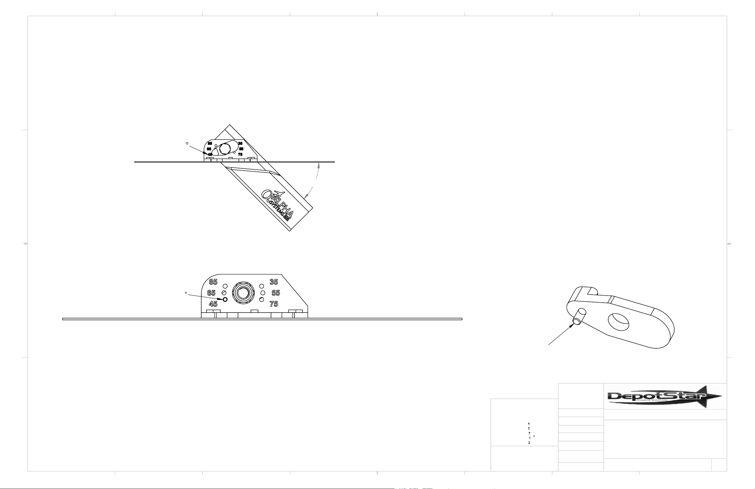
Positive Probe Lock System
The design of the probe and probe plate allows for the probe locking plate
to positively pin the probe from any possible movement after final assembly.
D
Due to differences of wing designs and the number of wing mounting
locations, it may become necessary to change the AOA probe angle to
allow for full scale and accurate electronic calibration. Depending on the
probe lock plate pin and which side of the AOA probe and hole is used, a
range of probe angles can be locked from 35 to 90 degrees, (see drawings
at the left). Start with a 45 degree angle, if a higher or lower angle is
required, material from the probe plate may have to be removed for
45
clearance of the probe to swing in the desired direction. Once the AOA
probe locking plate and the ¼ bolt is tightened to 60 inch lbs., the probe is
pinned in place.
D
C
B
45
45.00°
C
B
LOCKING PIN
PROBE LOCKING PLATE
PROD
UCT
:
UNLESS SPECIFIED,
A
G1 & G2 WING
8
7
6
5
4
UNITS ARE IN INCHES
AND TOLERANCESARE:
DIMENSIONS ARE IN INCHES
.X =
.03
.XX =
.XXX =
THE INFORMATION CONTAINED IN
THIS DRAWING IS THE SOLE PROPERTY
OF DEPOTSTAR
IN PART OR AS A WHOLEWITHOUT THE
WRITTEN PERMISSION OFDEPOTSTAR
3
.01
.005
DEG =
1
X/X =
1/16
. ANY REPRODUCTION
IS PROHIBITED.
DRAWN AARON
SCALE: NONE
X
DATE 10/19/10
SHEET: 1 OF 1
B
SIZE:
FINISH:
MATERIAL:
2
PROJECT:
DESCRIPTION:
PROBE MOUNTING PLATE
MOUNTING
ANGLES
PART #:
PROBE MOUNTING INCREMENTS
A
A
1
 Loading...