

Page 1
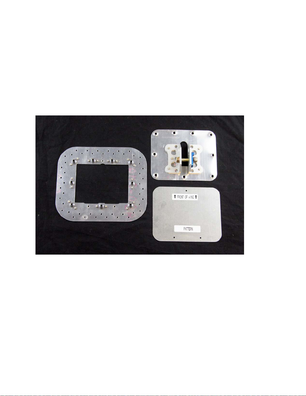
Doubler Plate
AOA Probe Mounting Plate
AOA Probe Mounting Template
7” Wide X 6” Deep
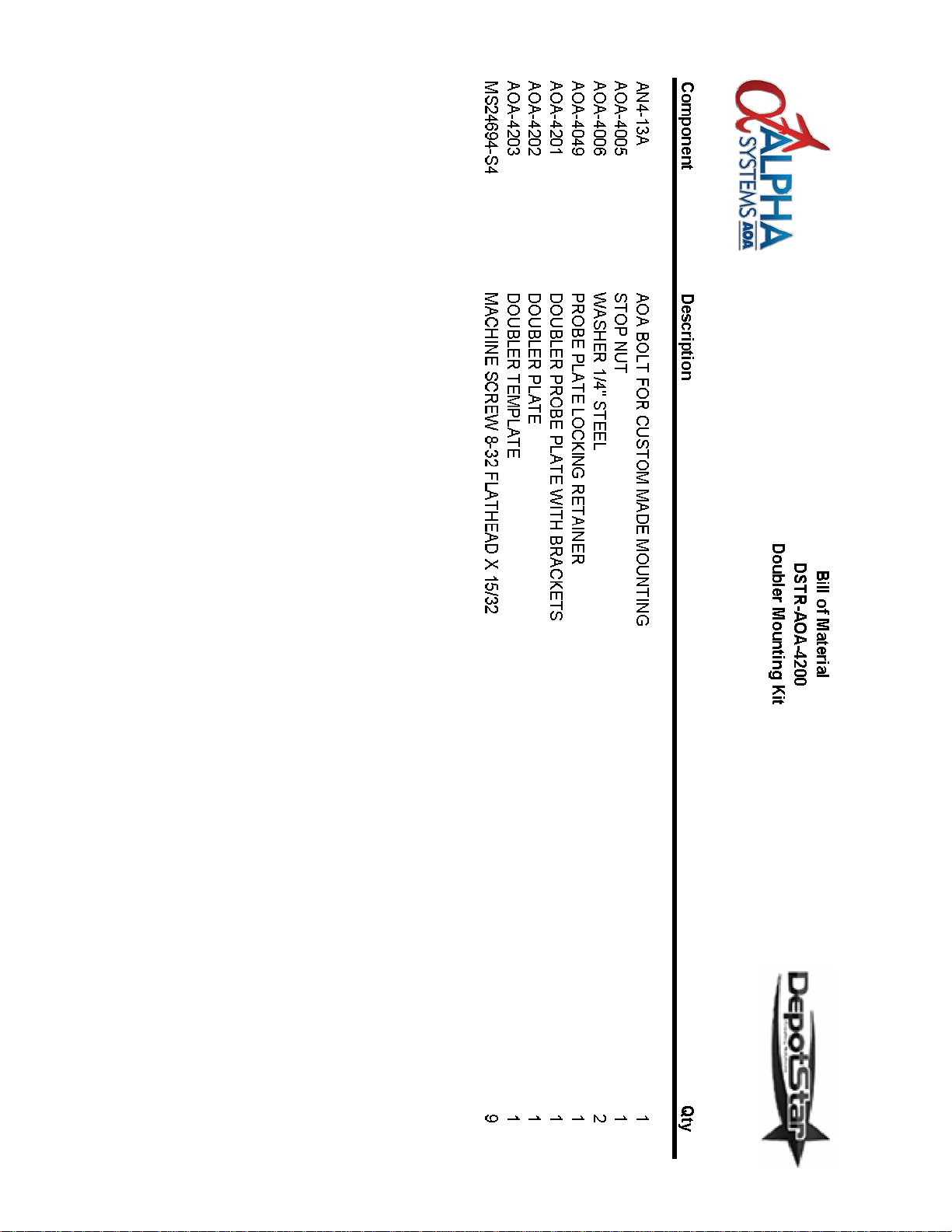
Doubler Plate Mounting Kit
DSTR-AOA-4200
Overview:
Alpha Systems AOA has created a premade AOA probe installation kit part number DSTR-AOA-4200
that was designed to allow solid mounting in a location when NO inspection cover or suitable
mounting option exists. The kit contains three main parts: 1.) AOA Probe Mounting Template
(AOA-4203), 2.) Doubler Plate (AOA-4202), 3.) CNC’d AOA Probe Mounting Plate (AOA-4201).
This kit will allow simple location, drilling, and accurate placement with minimum effort and time. The
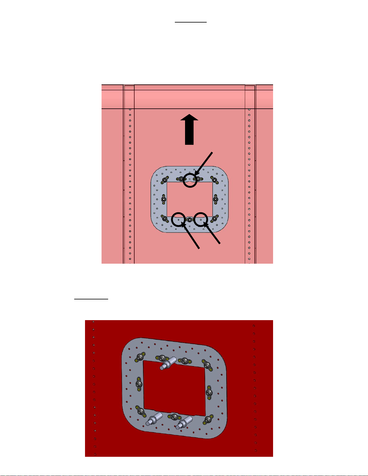
key to this installation is the 3 alignment holes that are in both the Doubler and the AOA probe
mounting plate template.
Mounting location specifications:
The objective to mounting the AOA sense probe is to be close to a 50 degree angle of the CHORD of
the wing (center of the leading edge to the center of the trailing edge). The prob e can be
adjusted after installation to accommodate various curvatures and positions under the wing. The
optimal location for the Alpha Systems AOA sense probe would be: 1.) Center ed betw een two ribs,
2.) Clearance inside the wing for the doubler; 7” Wide X 6” deep, 3.) A minimum o f 2 feet
outside the propeller arc, 4.) Location allowing for sensing undisturbed air at ALL attitudes,
slips, skids, NOTHING blocks or crea tes distu r bed air at the tip of the AOA probe, 5.) Typical
location suggestion; minimum of 6 inches from the leading edge of the wing and 12 inches
inboard from the back of the wing.
Optimal location; from the main spar forward (minimizes possibility of extreme curvatures from the
Chord line) and closer wing inboard. However, it can be mounted anywhere that allows sensing of
undisturbed air.
March 23, 2017 AOA 005 Rev A 1
Page 2
STEP 1:
Identify a suitable location on the OUTSIDE of the wing using the Doubler Plate
Drill out these 3 holes for referen ce and orien tation for both the
STEP 2:
Leading Edge
(AOA-4202) for size and clearance inside from any obstruction, structural member, and
controls. Be sure it meets the operational criteria, clears all ribs or spars, is not in a fuel
tank, or confined area inside the wing at the desired mounting location. Place the Doubler
Plate against the bottom wing surface, temporarily tape in place, locate the 3 alignment
holes, and drill with a number 40.
Doubler Plate (AOA-4202) to the wing. Next, using the doubler as a drill guide, drill all doubler
rivet holes with a #40 drill bit. Be careful to not let the drill wander and elongate the holes.
On the OUTSIDE of the wing, install Clecos in the three drilled holes to hold the
Doubler and Probe Mounting Template location.
March 23, 2017 AOA 005 Rev A 2
Page 3
Step 4:
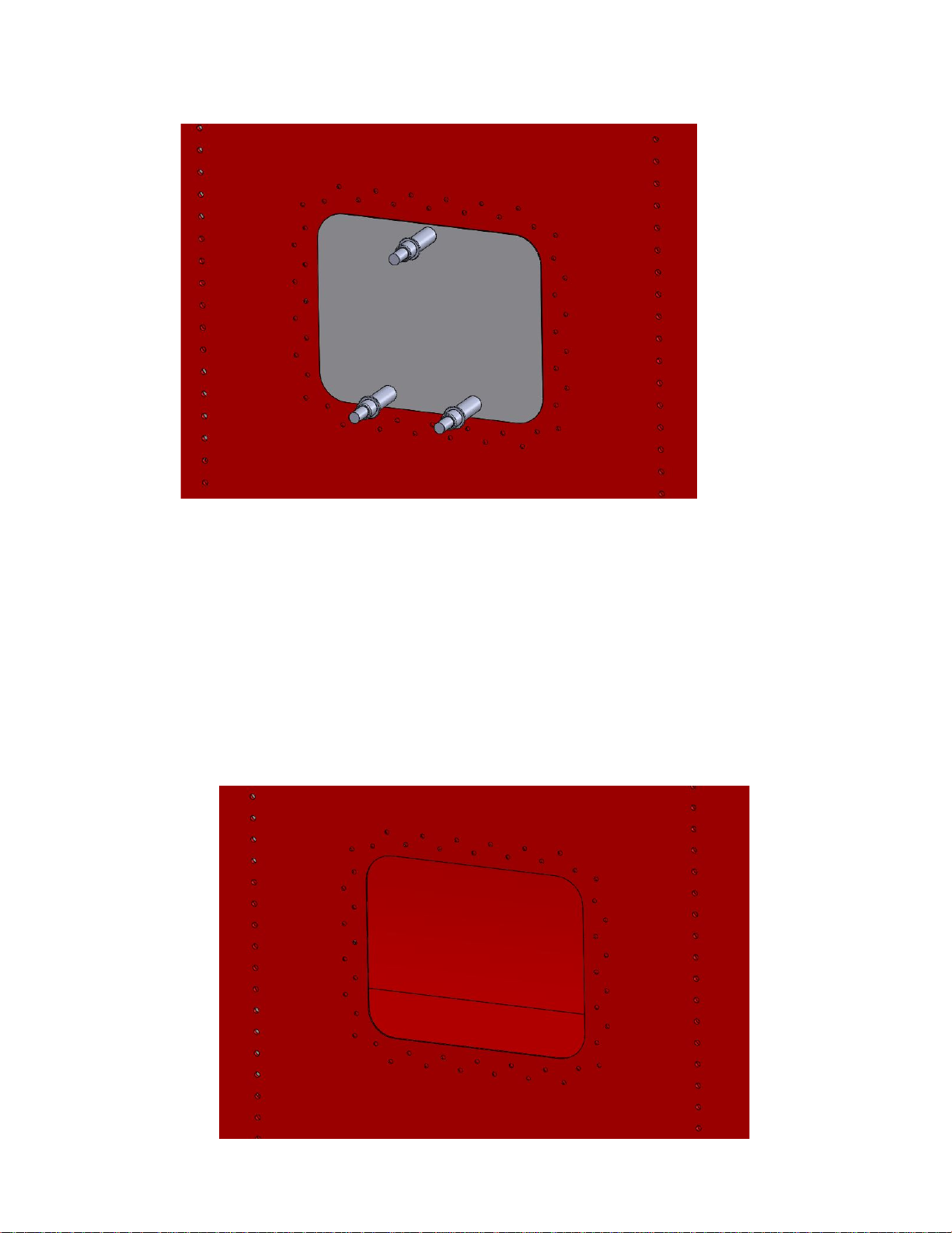
STEP 3
(AOA-4203) using the 3 reference holes. Scribe/mark around the edge of the AOA mounting
Template.
: Remove doubler, debur drilled holes, and Cleco the AOA Probe Mounting Template
clearance so that the AOA probe mounting plate can be flush m ounted when
complete.
Remove Template, discard, remove material inside scribe line, and make
March 23, 2017 AOA 005 Rev A 3
Page 4
Step 5:
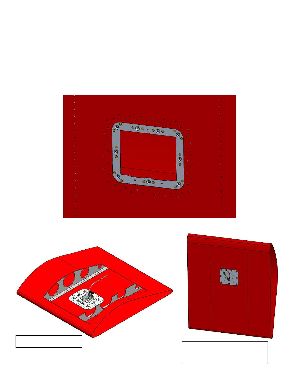
Inside final assembly
Bottom view of pr o be pla te
wing. After the opening in the wing is complete, slide the Doubler inside making sure that the
doubler is oriented to allow the AOA probe plate, position the probe facing forward in the wing.
Using a minimum of at least 4 Clecos, temporarily position the Doubler in place using the drilled
riveting holes. Check for complete fit and clearance of the AOA Probe Mounting Plate when all 8
screws are installed. Remove screws and complete the riveting process and final assembly.
The A&P, IA will determine best rivet size/type for final assembly of the doubler to the
installed with AOA
March 23, 2017 AOA 005 Rev A 4
Page 5
March 23, 2017 AOA 005 Rev A 5
 Loading...