

Page 1

CLASS A/B BIPOLAR POWER
AMPLIFIERS
PM3002E / PM6002E
PM6004E / PM12005E / PM1600DE
Page 2

ALPHASONIK WAS FOUNDED IN 1976 WITH ONE MISSION, TO
BRING STATE OF THE ART PERFORMANCE TO THE CAR AUDIO
ENTHUSIAST.
In those early years we pioneered such ground-breaking technologies
as amplier fan cooling and high voltage signal transfer which remain a
benchmark in high-end audio.
Today, the new Alphasonik is committed to pushing the envelope with
regard to technology, quality and value. Our electronics feature audiophile parts and circuit topology designed to let the full musical experience
come through, loud and clear. Our loudspeakers employ the latest high
technology materials and processes such as carbon reinforced woven
glass and titanium vapor deposition to deliver your music with tremendous impact, dynamics and resolution.
We stand behind our quality with one of the best warranties in consumer
electronics. Compare Alphasonik car audio products against anything
competition has to offer. We’re condent you will come to one conclusion...
Page 3

Introduction.................................................................................3
T
A
B
L
E
Features and Specications....................................................4-5
Planning & Mounting Your System.............................................6
Controls & Functions.............................................................7-14
High Level Input...................................................................15-16
Wiring Diagrams..................................................................17-22
Adjusting & Tuning....................................................................23
Troubleshooting........................................................................24
Warning / Disclaimer.................................................................25
Warranty..............................................................................26-27
O
F
C
O
N
T
E
N
T
Notes...................................................................................28-30
Page 4

N
T
R
O
D
U
C
T
O
N
I
Thank you for purchasing this Alphasonik product. Alphasonik products are specically engineered and designed for the mobile
audio environment. This manual contains important information about
installation, set-up procedures and integrating your new Alphasonik
product into your vehicle. With proper care and installation, your new
product will provide you with many years of high performance listening
enjoyment. We recommend having an Authorized Alphasonik Dealer
install your new product for optimal performance and to take advantage
I
of our warranty program. Before installing your new product, please
read through the manual to fully understand the application.
Before making any electrical connections, make sure that
you disconnect the battery’s ground cable to prevent the possibility of
short circuits or damage to your electronic equipment. If your vehicle’s
stereo (head unit) comes with an Anti-theft code, DO NOT disconnect
the battery. If you have the access code for the stereo (head unit),
please refer to the vehicle’s owner’s manual.
3
Page 5

Class A/B BIPOLAR Power Amplier
2 Ohm Stable (PM3002E / 6002E / 6004E / 12005E)
Mosfet High Speed Switching Supply
Tiffany-Style Input and Output RCA Jacks
RCA (Low Level) and Speaker (High Level)Inputs
Line Out
F
E
A
T
U
R
E
S
A
N
D
Bridgeable
Variable High Pass Filter: 50Hz-250Hz
Variable Low Pass Filter: 50Hz-250Hz
Variable Subsonic Filter: 20Hz-60Hz
Bass Boost Control: 45Hz 0 - +18dB
Remote Digital Voltmeter (PMA100VE)- Optional
Remote Bass Control (PMA10BE)-Optional
Remote Power On / Off By Car Stereo
Input Sensitivity: High 1V / 10V / Low 200mV - 8V
4-Way Protection Circuitry: Thermal, Short Circuit, Overload And
DC Offset
S
P
E
C
I
F
I
C
A
T
I
O
N
S
4
Page 6
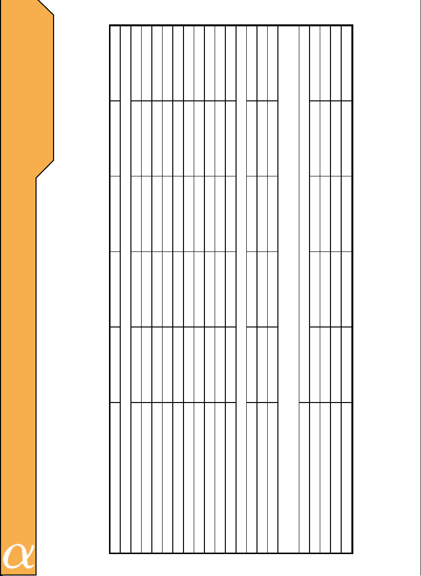
F
Variable Subsonic Filter
Variable Bass Boost at 45Hz
Dimensions
Length
Height
Width
Crossover
Selectable ON/OFF Crossover-Fully Variable 50Hz-250Hz / 18 db/Octave
Variable Low Pass
Variable High Pass
Signal to Noise Ratio
Damping Factor
Separation
Input Sensitivity
Input Impedance
Power Fuse
MODEL:
Power /4 Ohms
Power /2 Ohms
Power /1 Ohm
T.H.D.
E
A
T
U
R
E
S
A
N
D
S
P
E
C
F
C
A
T
O
N
S
I
I
I
PM3002E PM6002E PM6004E PM12005E PM1600DE
75 X 2 150 X 2 75 X4 75 X 4 & 200 X 1 300 X 1
5
0.05% 0.05% 0.05% 0.05%
N/A N/A N/A N/A N/A
120 X 2 240 X 2 120 X 4 120 X 4 & 320 X 1 600 X 1
>175 >250 >175 >250
>98db >98db >98db >95db
200mV-8V 200mV-8V 200mV-8V 200mV-8V 200mV-8V
63db 69db 60db 60db
20 Amp (2)20 Amp (2)20 Amp (2)40 Amp (2)30 Amp
10Kohms 10Kohms 10Kohms 10K ohms 10Kohms
2" 2" 2" 2" 2"
8 1/16" 11 7/8" 12 5/8" 18 15/16" 6 1/2"
9 1/4" 9 1/4" 9 1/4" 9 1/4" 9 1/4"
0~+18db 0~+18db 0~+18db 0~+18db 0~+18db
20Hz - 60Hz 20Hz - 60Hz 20Hz - 60Hz 20Hz - 60Hz 20Hz - 60Hz
50Hz-250Hz 50Hz-250Hz 50Hz-250Hz 50Hz-250Hz N/A
50Hz-250Hz 50Hz-250Hz 50Hz-250Hz 50Hz-250Hz 50Hz-250Hz
Page 7

Before beginning the installation, consider the following:
A. If you plan to expand your system by adding other components sometimes in
the future, ensure that adequate is left, and cooling requirements are met.
B. Are your components matched? The peak power rating of your speakers
must be equal or greater than the amplier’s. They also must be 2-8 ohms impedance (This information is normally printed on the speaker magnet).
C. Consider the length of your leads which should not be too long or short when
determining the mounting location. Pre-Amp input jacks require a length of high
quality shielded male to male RCA patch cord.
Mounting Your Amplier
The mounting position of your amplier will have a greater affect on its ability to
dissipate the heat generated during normal operation. This amplier has ample
heat sink for heat dissipation, and is designed with a thermal shutdown circuit
(for heat protection). DO NOT enclose the amplier in a small box or cover it so
that air is not able to ow freely.
Temperatures in car trunks have been measured as high as (155 F) in the summer time. As the thermal shut down point for the amplier is (185 F), it is easy
to see that it must be mounted in an area that provides for maximum cooling
capability. To achieve maximum advantage of convection air ow in an enclosed
trunk, mount the amplier in a horizontal position.
Cooling requirements are considerably relaxed when the mounting inside the
passenger compartment since the driver compartment will not allow temperatures to reach a critical point. Floor mounting under the seat is usually satisfactory as long as there is at least 1 inch of clearance above the amplier’s heat
sink for ventilation.
A. Select a suitable location that is convenient for mounting, is accessible for
wiring, and has ample room for air circulation and cooling.
B. Use the amplier as a template to mark the mounting holes. Remove the amplier and drill holes. Use extreme caution, inspect underneath surface before
drilling!
C. Secure the amplier using the screws provided.
Caution: Before connecting any wires to the amplier, disconnect the ground lead from the battery. Leave the ground lead
disconnected until you are done wiring the amplier.
P
L
A
N
N
N
G
&
M
O
U
N
T
N
G
Y
O
U
R
S
Y
S
T
E
M
I
I
6
Page 8
C
O
N
T
R
O
L
S
&
F
U
N
C
T
O
N
S
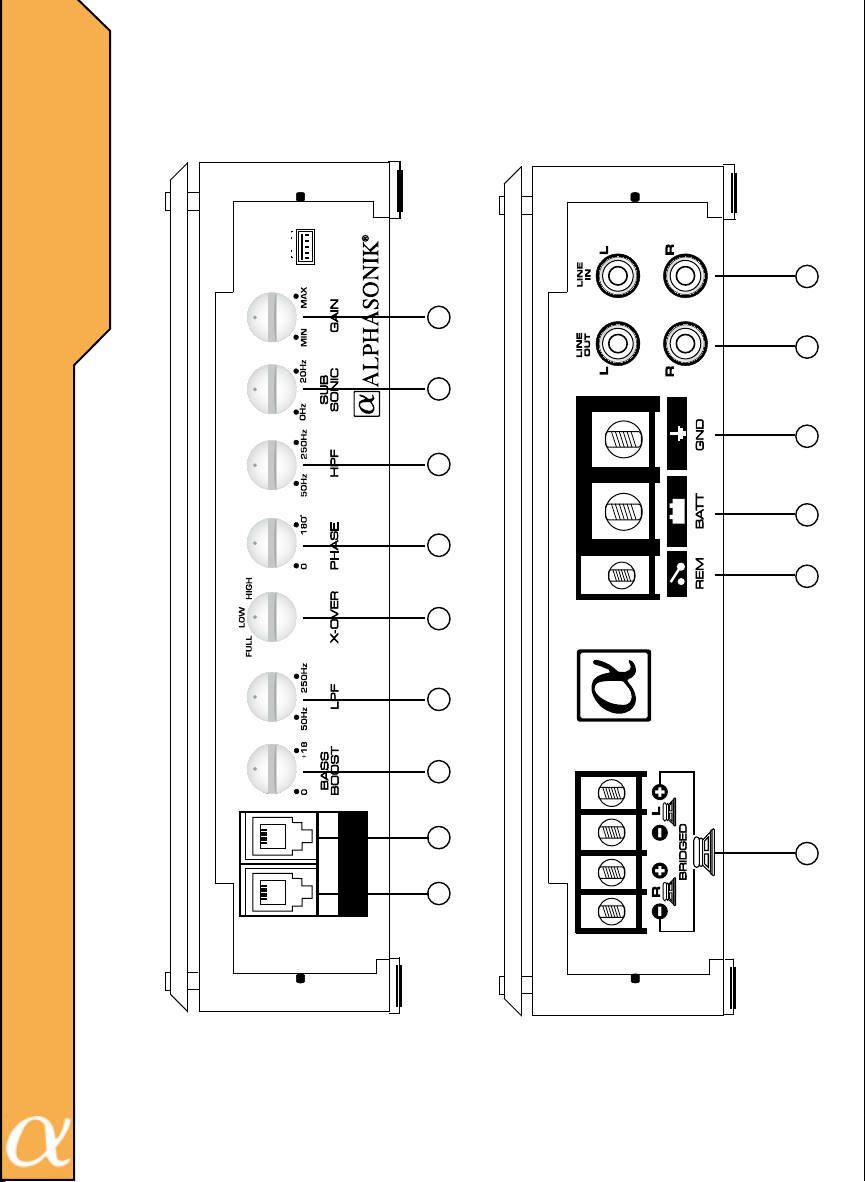
GR LR L
3
2
3
6
I
10 1213
7
11
8
5
9
4
BASS
REMOTE
DVM
PM3002E / PM6002E / PM1600DE
14
1
PM3002 / PM6002E / PM1600DE
7
Page 9
C
O
N
T
R
O
L
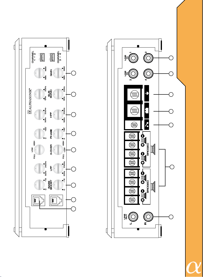
GR LR L
GR LR L
2
3
3
S
&
F
U
N
12
6
C
T
1011
7
I
O
N
8
S
5
9
4
REMOTE
14
13
PM6004E
PM6004E
DVM
1
8
Page 10
C
O
N
T
R
O
L
S
&
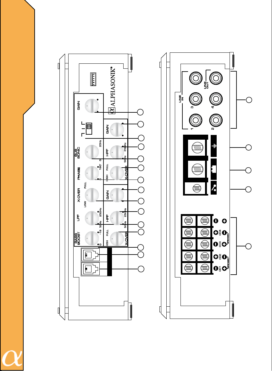
35G 24 1
HI - INPUT
5
5
F
U
N
C
T
O
N
S
3
1 + 2
8V 0.2
CH
1 / 2
CH
1 / 4
INPUT
SELECT
CH
I
1 / 5
BASS
DVM
CHANNEL
CHANNEL
REMOTE
2
2
8V 0.2
15
6
12
5
11
2
5
8V 0.2
10
95 10
4
14
3 + 4
13
CH5
7
8
1
PM12005E
PM12005E
9
Page 11
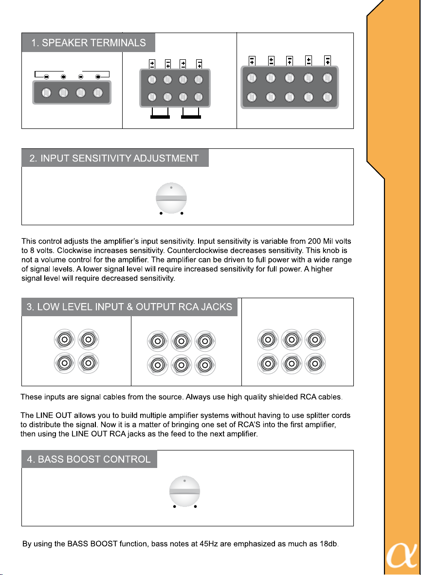
SPEAKER
BRIDGED
LR
PM3002E / 6002E
CH3
CH4
CH2 CH1
BRIDGED BRIDGED
GAIN
MAX MIN
SPEAKER
PM6004E
CH5 CH4 CH3
PM3002E / 6002E
PM6004E / 12005E
CH1
CH2
PM12005E
SPEAKER
C
O
N
T
R
O
L
S
&
F
U
N
C
T
O
N
S
I
LINE
LOW
OUT
INPUT
L
R
L
R
PM3002E / 6002E
CH3
CH4
LOW
INPUT
CH1/2CH3/4
CH1
CH2
PM6004E
BASS BOOST
0 +18dB
LOW
LINE
OUT
L
R
INPUT
CH1/2 CH3/4 CH5
CH1 CH3
CH2 CH4
LOW
INPUT
LINE
OUT
PM12005E
PM3002E / 6002E
PM6004E / 12005E
10
Page 12
C
O
N
T
R
O
L
S
&
F
U
N
C
T
O
N
S
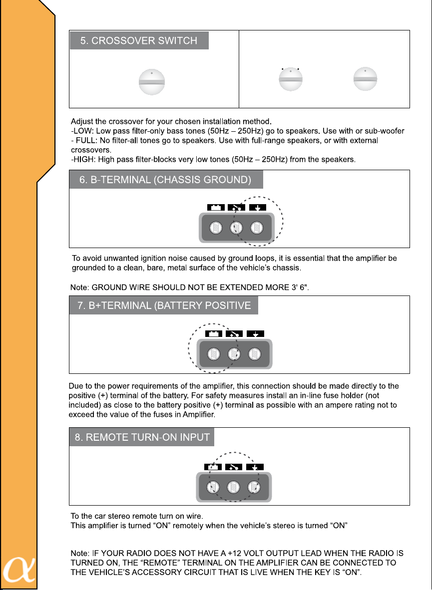
5 CHANEL
X-OVER
FULL
LOW
HIGH
PM3002E / 6002E / 6004E
POWER
GND
REM
BATT
I
FULL HIGH
X-OVER
PM3002E / 6002E
PM6004E / 12005E
X-OVER
FULL
LOW
PM12005E
11
POWER
BATT REM
POWER
REM
BATT
GND
PM3002E / 6002E
PM6004E / 12005E
GND
PM3002E / 6002E
PM6004E / 12005E
Page 13
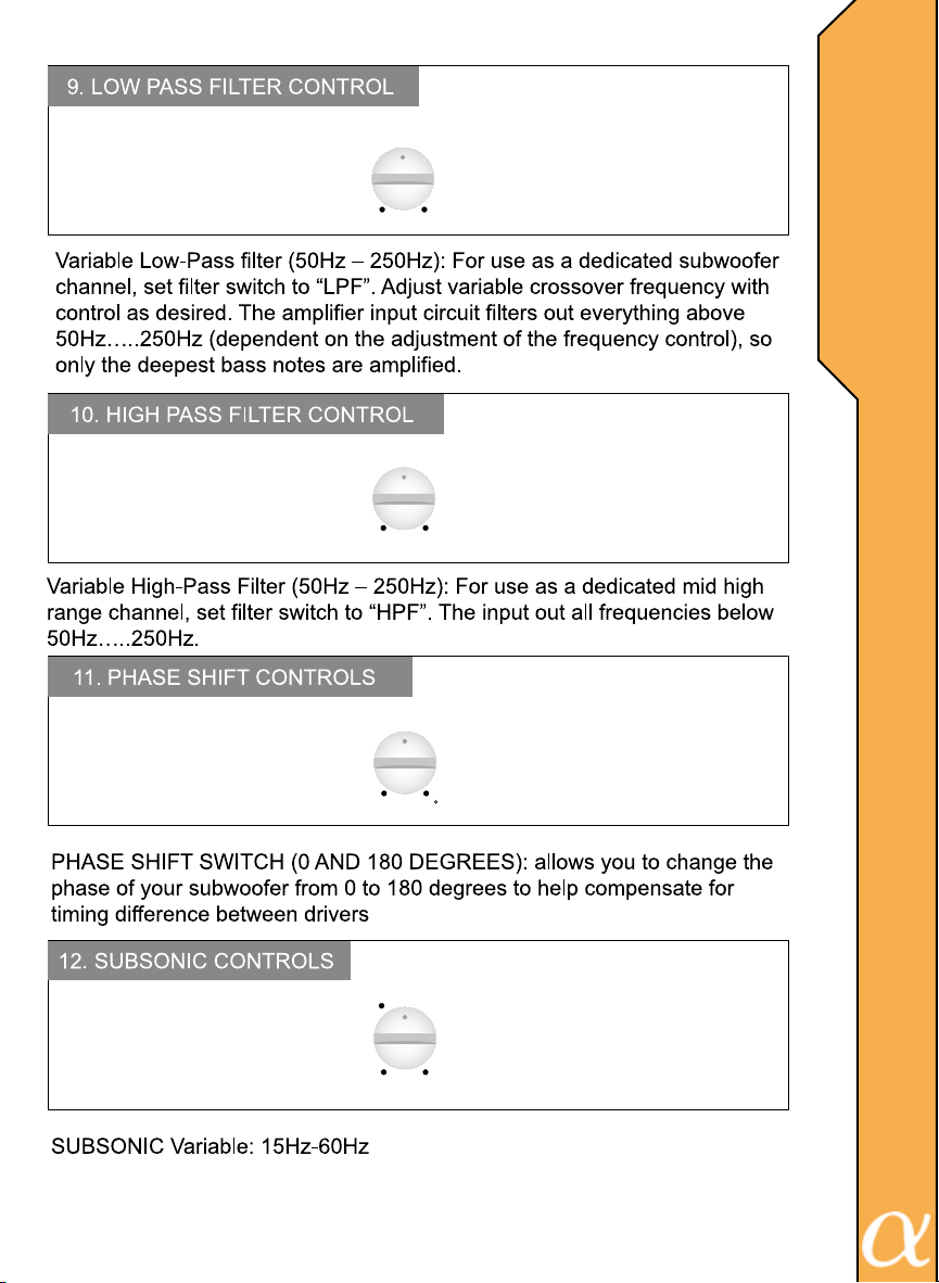
LPF
50 250Hz
HPF
50 250Hz
PM3002E / 6002E
PM6004E / 12005E
PM3002E / 6002E
PM6004E / 12005E
C
O
N
T
R
O
L
S
&
F
U
N
C
T
I
O
N
S
PHASE SHIFT
0 180
SUB SONIC
15
10 20Hz
PM3002E / 6002E
PM6004E / 12005E
PM3002E / 6002E
PM6004E / 12005E
12
Page 14
C
O
N
T
R
O
L
S
&
F
U
N
C
T
O
N
S
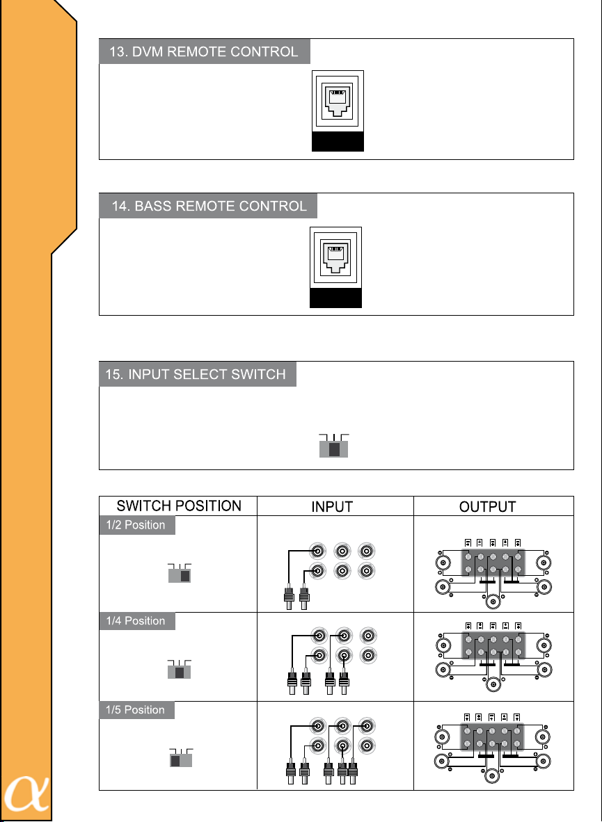
DVM
REMOTE
BASS
REMOTE
PM3002E / 6002E
PM6004E / 12005E
PM3002E / 6002E
PM6004E / 12005E
I
INPUT SELECT
CH
CH
1/5
CH
1/4
1/2
13
INPUT SELECT
CH
CH
1/4
1/5
INPUT SELECT
CH
CH
1/4
1/5
INPUT SELECT
CH
1/4
1/5
PM12005E
INPUT OUTPUT
CH1/2 CH3/4 CH5
CH1 CH3
CH
1/2
CH
1/2
CH
CH
1/2
CH2 CH4
CH1/2 CH3/4 CH5
CH1 CH3
CH2 CH4
CH1/2 CH3/4 CH5
CH1 CH3
CH2 CH4
LOW
INPUT
LINE
OUT
LOW
INPUT
LINE
OUT
LOW
INPUT
LINE
OUT
CH5 CH1CH2CH3CH4
BRIDGEDBRIDGED
CH5 CH1CH2CH3CH4
BRIDGEDBRIDGED
CH5 CH1CH2CH3CH4
BRIDGEDBRIDGED
Page 15
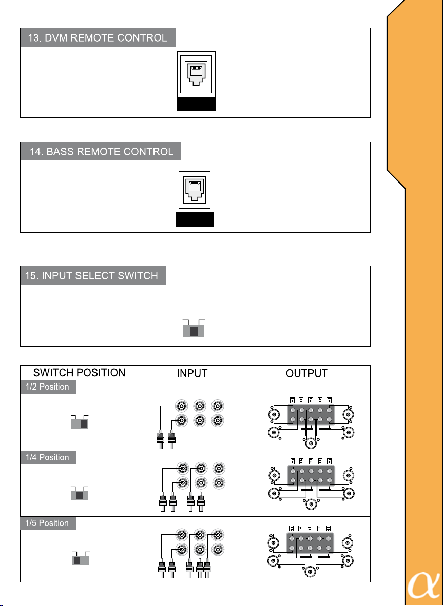
DVM
REMOTE
BASS
REMOTE
INPUT SELECT
CH
CH
1/4
1/5
C
O
N
T
R
PM3002E / 6002E
PM6004E / 12005E
O
L
S
&
F
U
N
C
PM3002E / 6002E
PM6004E / 12005E
T
I
O
N
S
CH
1/2
INPUT SELECT
CH
CH
1/4
1/5
INPUT SELECT
CH
CH
1/4
1/5
INPUT SELECT
CH
1/4
1/5
PM12005E
INPUT OUTPUT
CH1/2 CH3/4 CH5
CH1 CH3
CH
1/2
CH
1/2
CH
CH
1/2
CH2 CH4
CH1/2 CH3/4 CH5
CH1 CH3
CH2 CH4
CH1/2 CH3/4 CH5
CH1 CH3
CH2 CH4
LOW
INPUT
LINE
OUT
LOW
INPUT
LINE
OUT
LOW
INPUT
LINE
OUT
CH5 CH1CH2CH3CH4
BRIDGEDBRIDGED
CH5 CH1CH2CH3CH4
BRIDGEDBRIDGED
CH5 CH1CH2CH3CH4
BRIDGEDBRIDGED
14
Page 16
H
G
H
L
E
V
E
L
I
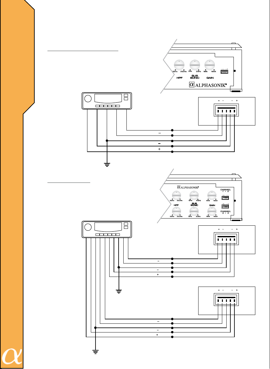
If the HIGH LEVEL INPUTS are used, do not use the
LOW LEVEL RCA inputs at the same time.
PM3002E / 6002E
GR LR L
N
P
U
T
I
R+
CHASSIS GND
R
L
L
GR LR L
HI - INPUT
PM6004E
GR LR L
GR LR L
GR LR L
CH 3/4
HI - INPUT
RR+
RR
CHASSIS GND
OR
OR
15
RF+
RF
CHASSIS GND
LF
LF
GR LR L
CH
HI - INPUT
Page 17
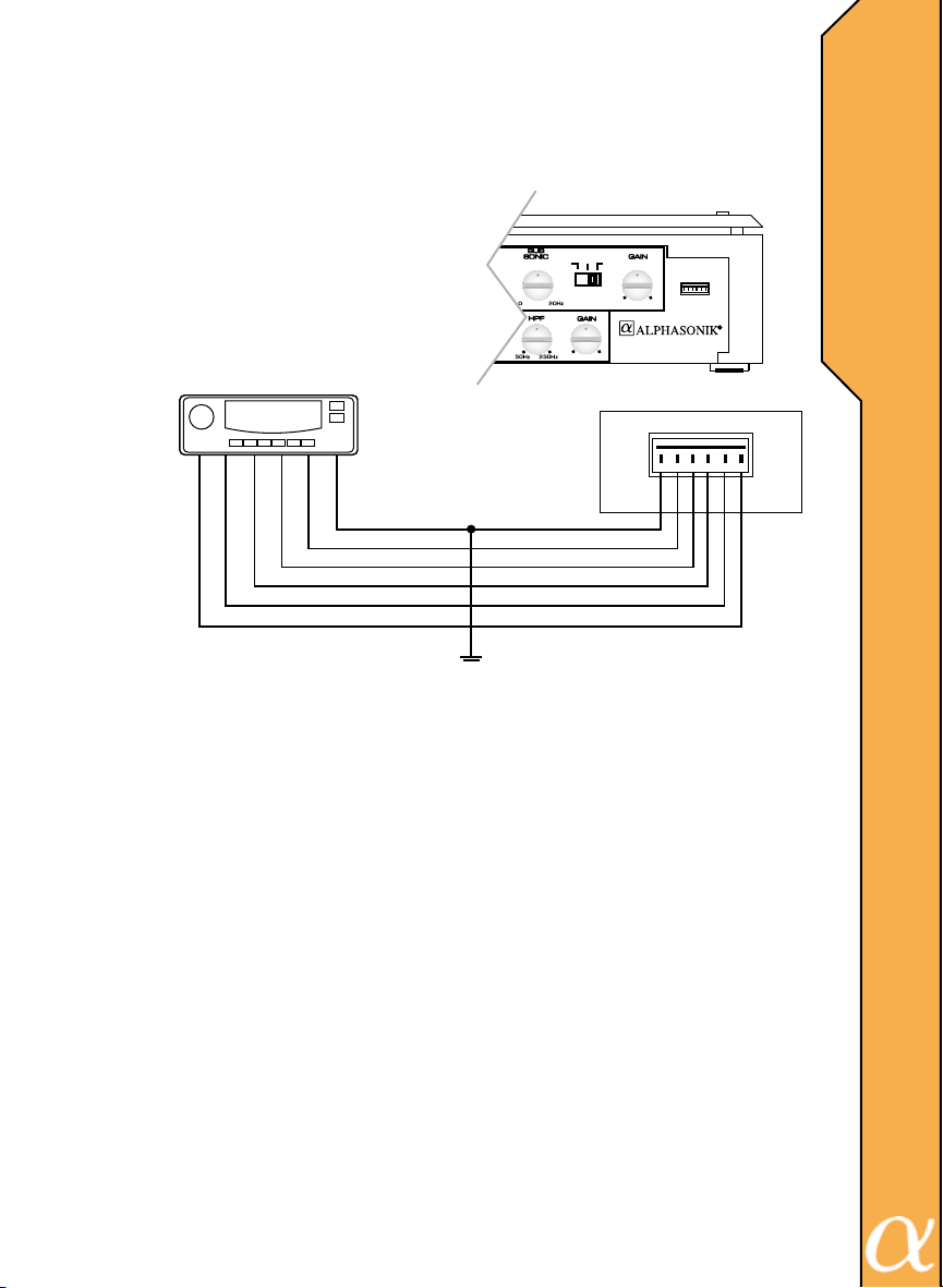
If the HIGH LEVEL INPUTS are used, do not use the
LOW LEVEL RCA inputs at the same time.
PM12005E
CH
1 / 5
CHASSIS GND
5CH
4CH
3CH
2CH
1CH
CH
1 / 4
INPUT
SELECT
8V 0.2
CH
1 / 2
8V 0.2
CHANNEL
1 + 2
35G 24 1
HI - INPUT
35G24 1
HI - INPUT
H
G
H
L
E
V
E
L
N
P
U
T
I
I
16
Page 18
W
I
R
I
N
G
D
I
A
G
R
A
M
S
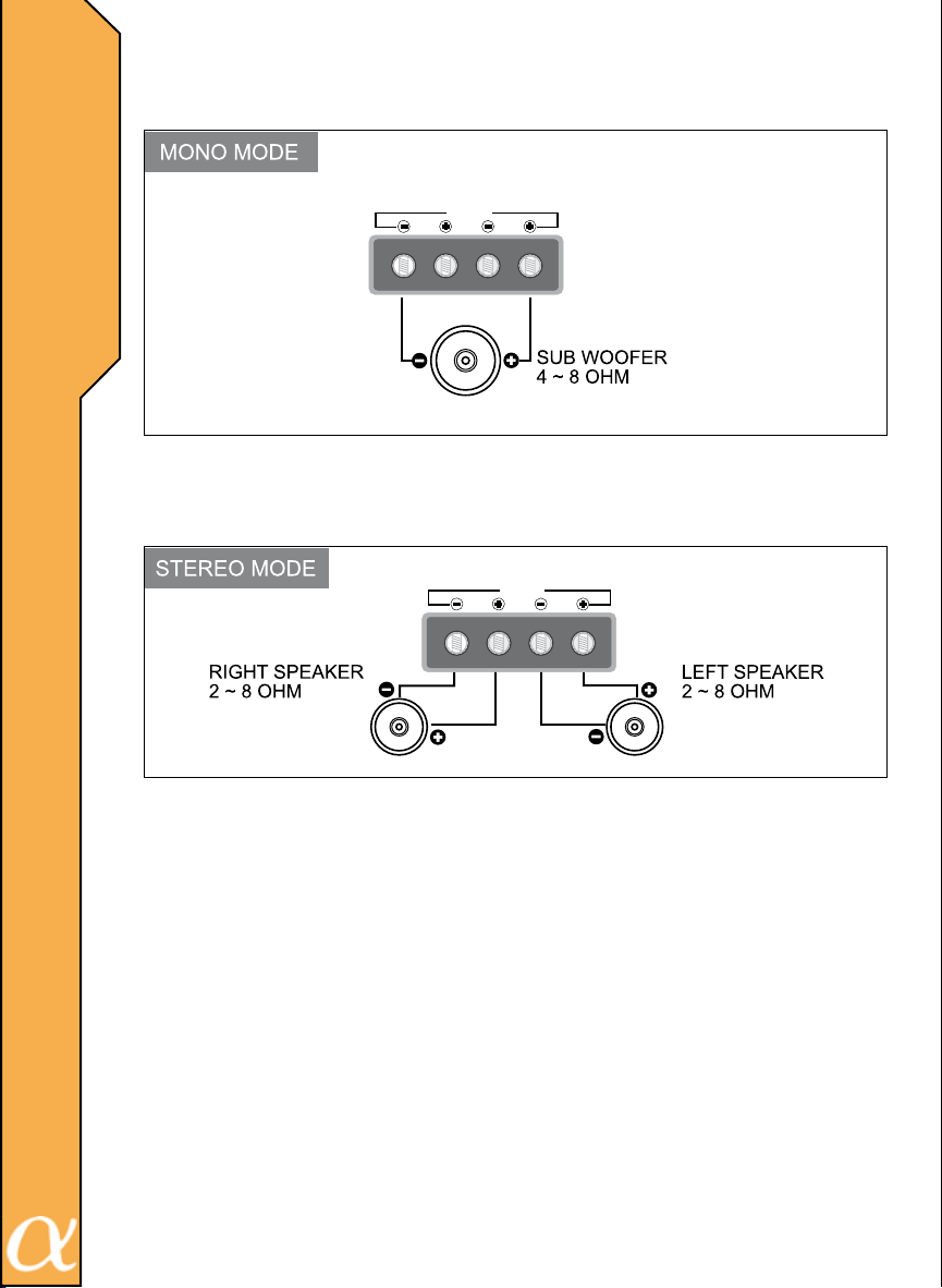
PM3002E / 6002E
SPEAKER
BRIDGED
LR
SPEAKER
BRIDGED
LR
17
Page 19
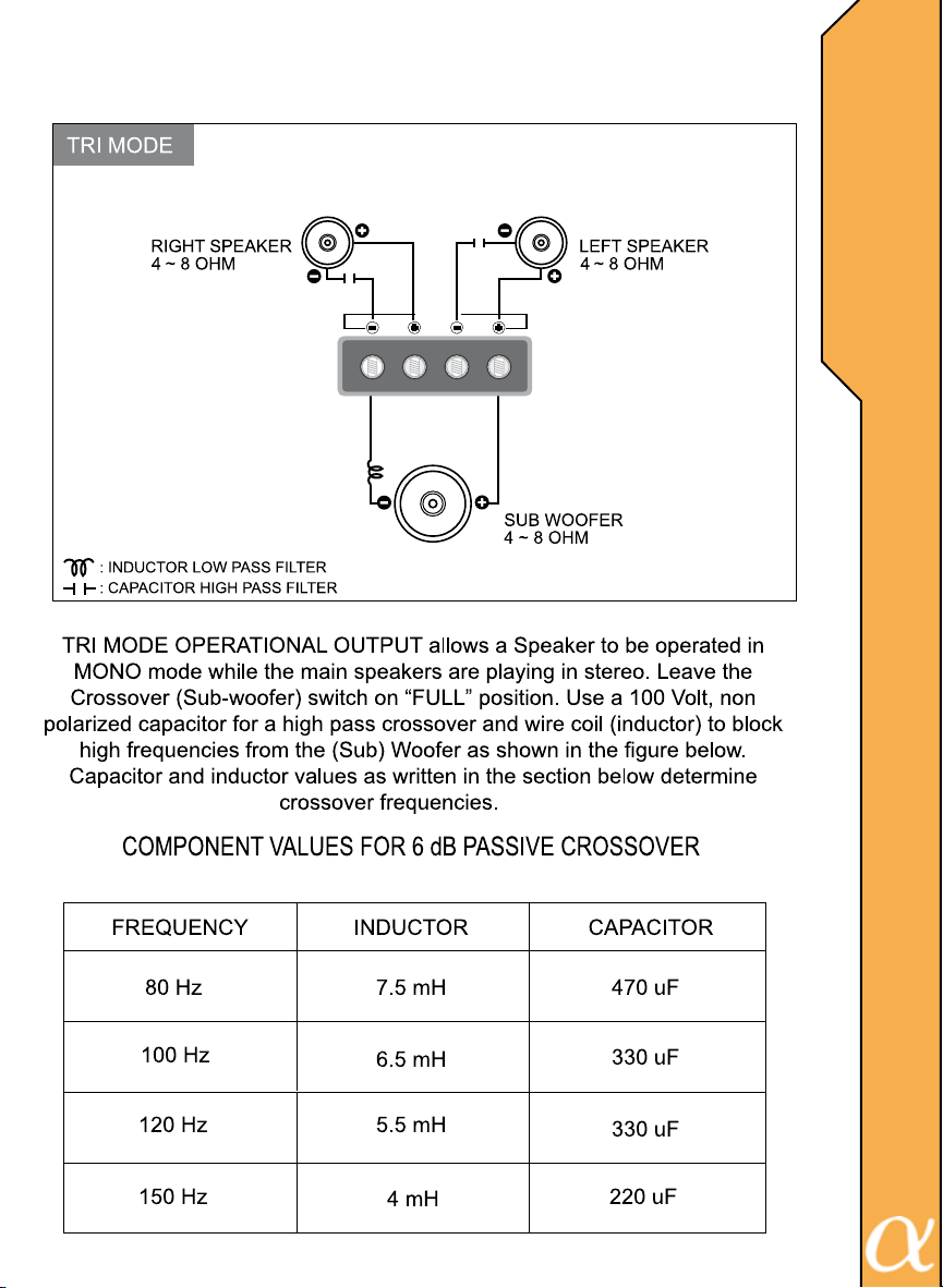
PM3002E / 6002E
SPEAKER
BRIDGED
W
I
R
I
N
G
D
I
A
LR
G
R
A
M
S
18
Page 20
W
R
N
G
I
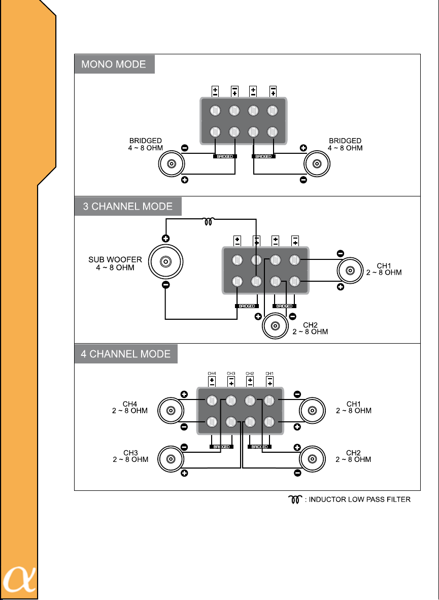
PM6004E
I
CH3
CH4
CH2 CH1
D
A
G
R
A
M
S
SPEAKER
I
CH4 CH3 CH2 CH1
SPEAKER
19
Page 21
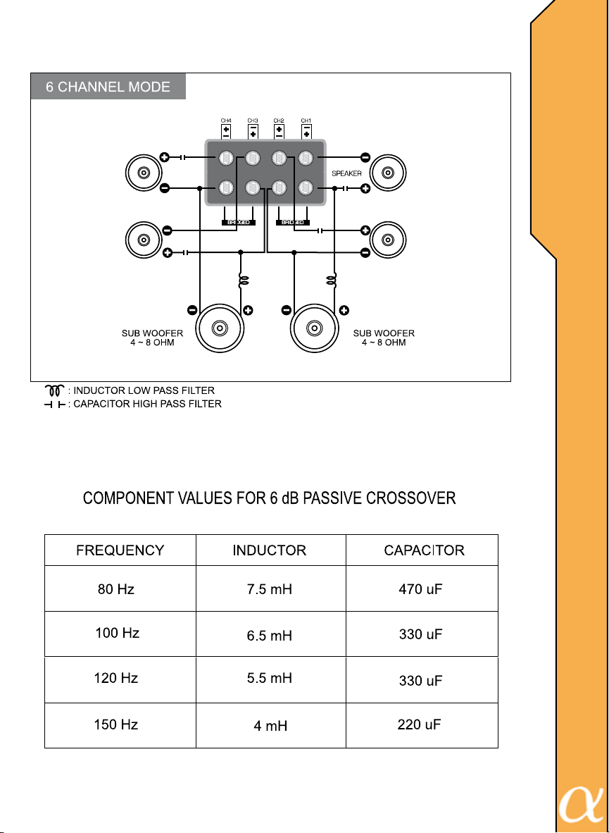
PM6004E
W
I
R
I
N
G
CH 4
4 ~ 8 OHM
CH 3
4 ~ 8 OHM
CH 1
4 ~ 8 OHM
CH 2
4 ~ 8 OHM
D
I
A
G
R
A
M
S
20
Page 22
W
R
N
G
D
A
G
R
A
M
S
I
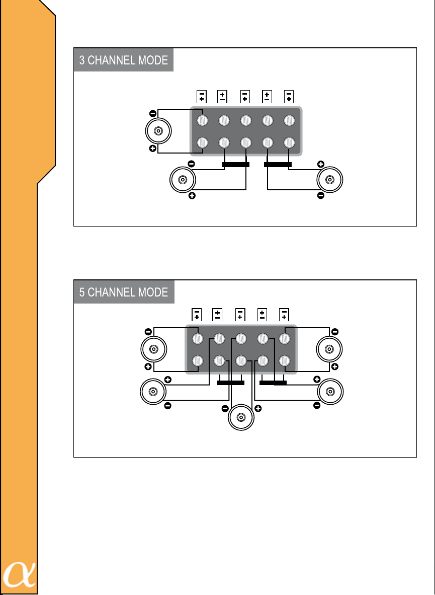
PM12005E
I
CH5 CH1CH2CH3CH4
I
CH 5
2 ~ 8 OHM
CH 3 / 4
4 ~ 8 OHM
BRIDGEDBRIDGED
CH1 / 2
4 ~ 8 OHM
CH5 CH1CH2CH3CH4
21
CH 5
2 ~ 8 OHM
CH 4
2 ~ 8 OHM
CH 3
2 ~ 8 OHM
CH 1
2 ~ 8 OHM
BRIDGEDBRIDGED
CH 2
2 ~ 8 OHM
Page 23
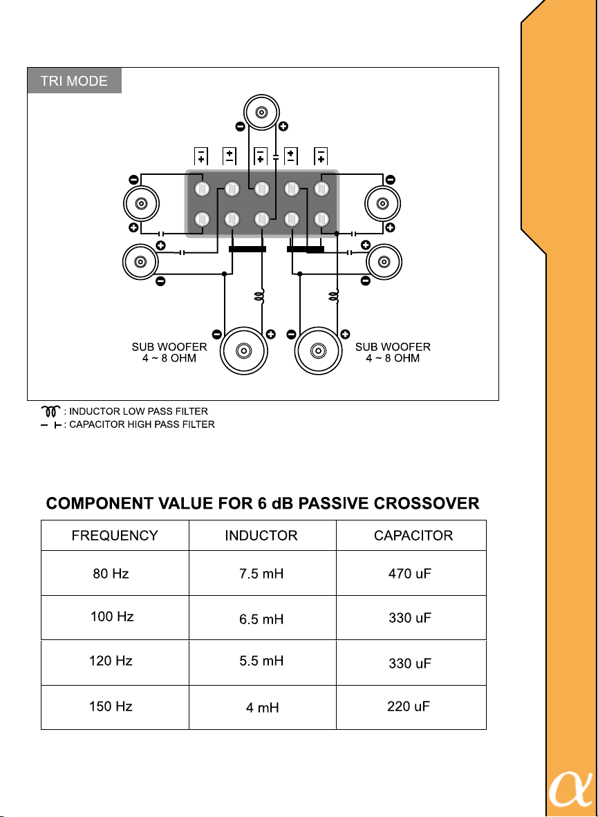
PM12005E
CH 5
4 ~ 8 OHM
CH 4
4 ~ 8 OHM
CH 3
4 ~ 8 OHM
CH5 CH1CH2CH3CH4
W
I
R
I
N
G
D
I
CH 1
4 ~ 8 OHM
A
G
R
BRIDGEDBRIDGED
CH 2
4 ~ 8 OHM
A
M
S
22
Page 24
A
D
J
U
S
T
N
G
&
T
U
N
N
G
Turning On The Amplier
The amplier automatically turns on a few seconds after you turn vehicle’s ignition switch to ACC ON or turn on your auto sound system, depending upon how
you wired the system. The POWER indicator on the top of the amplier illuminates when the amplier is on.
I
I
Important: Your amplier requires 90 amps or more of power from your vehicle’s
battery during operation. To protect your battery from your battery from discharging, do not operate the amplier unless your vehicle us running.
Adjusting The Audio Level (“Gain Matching”) By Ear
For best performance, you must match the amplier’s input sensitivity to your
source unit’s maximum output level. The GAIN CONTROL (MIN / MAX) located
on the side of the amplier is designed to do this. It is Not a volume control. It
adjusts the incoming signal level so that the source unit and amplier reach
maximum output at the same time. This assures that maximum system is
achieved with minimal distortion.
1. Turn the GAIN CONTROL (MIN / MAX) fully counterclockwise to MIN.
2. Play full frequency music that has continuous high levels (FM pop music is a
good choice).
3. Turn up the source unit’s volume control until just before you hear the source
unit’s distortion or 90% of full output (which ever comes rst).
4. SLOWLY turn the GAIN CONTROL clockwise until just before you hear
amplier or speaker distortion, until you reach a maximum comfortable listening
level (which ever come rst).
5. Turn the source unit’s volume control back to a desire comfortable listening
level and enjoy.
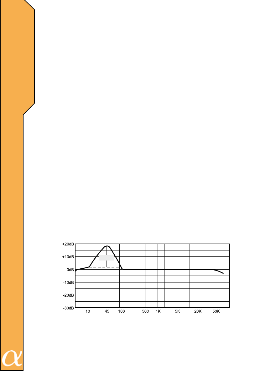
FREQUENCY RESPONSE
23
Plus 18dB
@45Hz
RESPONSE (dB)
FREQENCY (Hz)
The BASS BOOST CONTROL raises the amplier output up to 18db at frequencies tightly centered around 45 Hz. This “bump” can have a dramatic affect
on the bass system’s apparent volume. Use caution (!) when adjusting this
control as serious subwoofer damage may result from overpowering or overexcursion.
Page 25
T
R
O
U
B
L
E
S
H
O
O
T
N
G
I
24
Page 26

W
A
R
N
I
N
G
A
N
D
D
I
S
C
L
A
I
M
E
R
Investigate the layout of your vehicle thoroughly before
drilling or cutting. Take care when you work near the gas tank,
gas lines, hydraulic lines, electrical components and electrical
wiring. Do not use the equipment unmounted. Attach this system securely to prevent damage, particularly in the event of an
accident or aggressive driving. Do not mount the system so that
wire connections are unprotected or are subjected to pinching
or damage from nearby objects. Before connecting or disconnecting power connections at the system power terminals, disconnect the +12V DC wire at the battery end. Conrm that your
source unit and other equipment are turned off while connecting
the input terminals. If you need to replace the power fuse, replace it only with a fuse identical to the provided fuse. Using a
fuse of different type or rating may result in damage to the system, which is not covered by the manufacturer’s warranty. Do
not install any product where it may be subjected to excessive
heat, moisture and dust or where it may be repeatedly kicked,
brushed or bumped. Make absolutely sure that the terminals
for the products are connected to the proper inputs and outputs
from the music source. Never run the wiring on the outside of
the vehicle or under it where it can be damaged by road hazards
or any moving parts of the vehicle. Use existing wire channels,
sills, panels and molding strips inside the vehicle to hide the wiring for safety and a neat appearance.
25
DISCLAIMER
IMPORTANT: Never cut any metal that is an integral part
of the vehicle’s safety or structural support system. If you are
unsure, it is best to have the product professionally installed by
an Authorized Alphasonik Dealer. Never sacrice your safety for
sound.
Page 27

Alphasonik, Inc. warrants this product against all defects in material and
workmanship for a period of one (1) year from the date of original purchase
provided it was purchased from an Authorized Alphasonik, Inc. Dealer.
The conditions of this warranty and the extent of the responsibility of Alphasonik, Inc. under this warranty are as follows:
1. DATED PROOF OF PURCHASE IS REQUIRED FOR WARRANTY SERVICE OF THIS PRODUCT. Information about Alphasonik, Inc.
authorized warranty service may also be obtained at www.alphasonikinc.com
or by contacting or writing Alphasonik, Inc. at the address listed on the back
of this booklet.
2. This warranty will become void if service is performed by any
one other than an approved Alphasonik, Inc. Warranty Service Center.
3. This warranty does not apply to any product which has been
subjected to misuse, neglect or accident, or which has had the warranty
seal broken, serial number altered, defaced or removed, or which has been
connected, installed adjusted or repaired other than in accordance with the
instructions furnished by Alphasonik, Inc.
4. This warranty does not cover car static, electrical interference,
adjustments or labor costs for the removal or reinstallation of the unit for
repair.
5. The sole responsibility of Alphasonik, Inc. under this warranty
shall be limited to the repair or replacement thereof, at the sole discretion of
Alphasonik, Inc.
6. If it becomes necessary to send the product or any defective
part to Alphasonik, Inc. or an authorized service station, the product must
be shipped in its original or equivalent carton, fully insured, with shipping
charges prepaid. Alphasonik, Inc. will not assume any responsibility for any
loss or damage incurred in shipping.
W
A
R
R
A
N
T
Y
26
Page 28

W
A
R
R
A
N
T
Y
C
O
N
T
I
N
U
E
D
7. This warranty is not transferable and protects the original purchaser provided they reside and made their purchase in the United States.
International consumers may contact their local retailer or distributor for warranty information.
8. ALL IMPLIED WARRANTIES, EXCEPT TO THE EXTENT PROHIBITED BY APPLICABLE LAW, SHALL HAVE NO GREATER DURATION
THAN THE WARRANTY PERIOD SET FORTH ABOVE. UNDER NO
CIRCUMSTANCES SHALL ALPHASONIK INC. BE LIABLE FOR ANY LOSS
OR DAMAGE, DIRECT OR CONSEQUENTIAL, ARISING OUT OF THE
USE OR INABILITY TO USE THE PRODUCT. BECAUSE SOME STATES
DO NOT ALLOW LIMITATIONS ON HOW LONG AN IMPLIED WARRANTY
LASTS OR EXCLUSIONS OR LIMITATIONS OF INCIDENTAL OR CONSEQUENTIAL DAMAGES, THE ABOVE LIMITATIONS OR EXCLUSIONS MAY
NOT APPLY TO YOU.
9. THIS WARRANTY GIVES YOU SPECIFIC LEGAL RIGHTS AND
YOU MAY ALSO HAVE OTHER RIGHTS THAT VARY FROM STATE TO
STATE.
10. Should you have any difculties with the performance of this
product during warranty or with any Alphasonik, Inc. authorized service
center, you may contact the Alphasonik, Inc. National Service Manager at
the address listed on the back of the booklet card or call 714.670.8950 for a
listing of Authorized Warranty Service Centers in your area.
INSTALLED WARRANTY
(When purchased from and installed by an Authorized Alphasonik, Inc.
Dealer)
27
Speaker and Accessories: 1-year over-the-counter defective exchange plus
1-year repair or replacement at the sole discretion of Alphasonik, Inc.
Electronics: 1-year over-the-counter defective exchange, plus 1-year repair
or replacements at the sole discretion of Alphasonik, Inc.
An Alphasonik Extended Warranty Registration Card must be submitted to
Alphasonik, Inc. within 30 days of purchase. To process any warranty claim,
Alphasonik, Inc. will require the dated proof of purchase, which must specically show the model and serial number and that installation was provided
for the product in question. All other terms per Alphasonik, Inc.’s standard
one-year warranty apply.
Page 29

N
O
T
E
S
28
Page 30

N
O
T
E
S
29
Page 31

N
O
T
E
S
30
Page 32

ALPHASONIK INC.
7050 VILLAGE DRIVE BLDG. G
BUENA PARK, CALIFORNIA. 90621
TEL: (714)670-8950 · FAX: (714)670-8959
www.alphasonikinc.com
 Loading...