

Page 1

PSW610E / PSW612E
R
ALPHASONIK
Owner's Manual
Alpha 600 Series
Subwoofers
Page 2

ALPHASONIK WAS FOUNDED IN 1976 WITH ONE MISSION, TO
BRING STATE OF THE ART PERFORMANCE TO THE CAR AUDIO
ENTHUSIAST.
In those early years we pioneered such ground-breaking technologies
as amplier fan cooling and high voltage signal transfer which remain a
benchmark in high-end audio.
Today, the new Alphasonik is committed to pushing the envelope with
regard to technology, quality and value. Our electronics feature audiophile parts and circuit topology designed to let the full musical experience
come through, loud and clear. Our loudspeakers employ the latest high
technology materials and processes such as carbon reinforced woven
glass and titanium vapor deposition to deliver your music with tremendous impact, dynamics and resolution.
We stand behind our quality with one of the best warranties in consumer
electronics. Compare Alphasonik car audio products against anything
competition has to offer. We’re condent you will come to one conclusion...
Page 3

Introduction.................................................................................3
T
A
B
L
E
Features and Specications.......................................................4
Building an Enclosure.............................................................5-9
Subwoofer Parameters.............................................................10
Wiring Diagrams..................................................................11-13
Troubleshooting........................................................................14
Warning / Disclaimer.................................................................15
Warranty............................................................................16 - 17
Notes........................................................................................18
O
F
C
O
N
T
E
N
T
3
Page 4

N
T
R
O
D
U
C
T
O
N
I
Thank you for purchasing this Alphasonik product. Alphasonik products are specically engineered and designed for the mobile
audio environment. This manual contains important information about
installation, set-up procedures and integrating your new Alphasonik
product into your vehicle. With proper care and installation, your new
product will provide you with many years of high performance listening
enjoyment. We recommend having an Authorized Alphasonik Dealer
install your new product for optimal performance and to take advantage
I
of our warranty program. Before installing your new product, please
read through the manual to fully understand the application.
Before making any electrical connections, make sure that
you disconnect the battery’s ground cable to prevent the possibility of
short circuits or damage to your electronic equipment. If your vehicle’s
stereo (head unit) comes with an Anti-theft code, DO NOT disconnect
the battery. If you have the access code for the stereo (head unit),
please refer to the vehicle’s owner’s manual.
3
Page 5

All Alphasonik 600 Series cast basket subwoofers feature our patent pending
input and output terminals. Congure voice coils or drivers in series or parallel
with no fuss and no cramped or frayed wires. Terminals are audiophile grade
nickel-plated, machined brass – compression t with Allen head setscrews
PROPRIETARY HEAT SINK
All Alphasonik 600 Series subwoofers have motor structures encased in patent pending, cast aluminum, machine nished heat sinks. Power handling is
enhanced because excess heat is quickly absorbed and transferred to the
environment. The music may get hot but our subs run cool.
BASKET WEAVE, KEVLAR® REINFORCED KRAFT PULP CONE
All Alphasonik 600 Series subwoofers use our environmentally treated Kevlar
reinforced, Kraft pulp cone – the most neutral sounding material in the industry. Virgin, long-ber Kraft pulp is air cured and strengthened with Kevlar®. If
you beat on our subs, they hit back.
HIGH TENSILE STRENGTHDUAL LAYER SURROUND
All Alphasonik 600 Series subwoofers feature a massive 2-layer, high-travel
surround for reliability and control at maximum excursion
PSW610E
10” ALPHA 600 SERIES SUBWOOFER
Proprietary Cast Aluminum Alloy Machine Cut “Alpha” Basket
Proprietary Cooling Rings for Motor Assembly (Patent Pending)
Kevlar® Reinforced Composite Balanced & Laminated Cone
High Tensile Strength Two-Layer Surround for Enhanced Control
Flat Progressive Rate Nomex® Damper w/ Spiral-Woven Leads
75oz. Double Stack Magnet
Rated at 600 Watts RMS
87dB Efciency
Frequency Response of 33Hz to 500Hz
Dual 4 ohm 2” Voice Coils
8-Gauge Sure-Lok Input and Output Terminals (Patent Pending)
Mounting Dimensions — Depth: 150mm / 6”
Through Hole: 225mm / 8 7/8” Diameter: 258mm / 10 3/16”
F
E
A
T
U
R
E
S
A
N
D
S
P
E
C
F
C
A
T
O
N
S
I
I
I
PSW612E
12” ALPHA 600 SERIES SUBWOOFER
Proprietary Cast Aluminum Alloy Machine Cut “Alpha” Basket
Proprietary Cooling Rings for Motor Assembly (Patent Pending)
Kevlar® Reinforced Composite Balanced & Laminated Cone
High Tensile Strength Two-Layer Surround for Enhanced Control
Flat Progressive Rate Nomex® Damper w/ Spiral-Woven Leads
75 oz. Double Stack Magnet
Rated at 700 Watts RMS
89dB Efciency
Frequency Response of 30Hz to 500Hz
Dual 4 ohm 2 1/2” Voice Coils
8-Gauge Sure-Lok Input and Output Terminals (Patent Pending)
Mounting Dimensions — Depth: 164mm / 6 1/2”
Through Hole: 275mm / 10 7/8” Diameter: 312mm / 12 5/16”
4
Page 6

B
U
L
D
N
G
Now that you know about subwoofer specications it’s time to learn about building subwoofer boxes. If you’ve done any woodworking you shouldn’t have much
I
trouble when building a subwoofer enclosure. One of the main differences will
probably be the material used in building subwoofer boxes as compared to
other woodworking projects. When building a custom subwoofer box you will
want to use minimal MDF (medium density berboard).
I
TOOLS REQUIRED TO BUILD AN ENCLOSURE
A
N
E
N
C
L
O
S
U
R
E
Safety goggles
Table saw or circular saw
Powered screw gun
Router or jig saw
Variety of sizes of drill bits
Wood glue
Silicone
Wood screws
To ensure your safety while building an enclosure, please read all manuals for
the power tools you will be using, as they will include valuable information on
handling the tools and safety tips.
5
Page 7

If you’re planning to build your own enclosure and are confused
in what type of enclosure best suits your needs this page will help you
choose what enclosure ts your needs. There are many different types of
enclosures. The two most common used enclosures are sealed and vented
enclosure. This page will show the advantages and disadvantages of the
two enclosures.
Advantages of a sealed enclosures
*High power handing capability
*Great transient response
*Tolerant of minor enclosure size variation
*Easy to construct
*Smooth rolloff (12dB/octave)
Disadvantages of a sealed enclosures
*Requires a woofer with a long excursion for better low bass frequency
response.
*Can have lower sensitivity than ported enclosures.
*When using high power and small enclosures, the woofer is not in an ideal
cooling environment.
*Less low bass as compared to a properly tuned vented enclosure above
the ported tuning frequency.
Advantages of a vented enclosure
*Increased output around vented tuning
*Higher power handling above the port tuning frequency
*Extended frequency response
*Magnet is in a good cooling environment
*Handles higher bass frequencies with less distortion
B
U
L
D
N
G
A
N
E
N
C
L
O
S
U
R
E
I
I
Disadvantages of a vented enclosure
*Vented enclosure transient response is not as good as sealed boxes because of the resonant effect of the vent tuning
*Midrange sound coming from inside the enclosure through the vent
can produce unpleasant sound coloration.
*Loss of cone movement control below vent tuning, which can result in high
distortion and mechanical failure of the driver.
*Lower power handling below the port tuning frequency.
6
Page 8
B
U
L
D
N
G
A
N
E
N
C
L
O
S
U
R
E
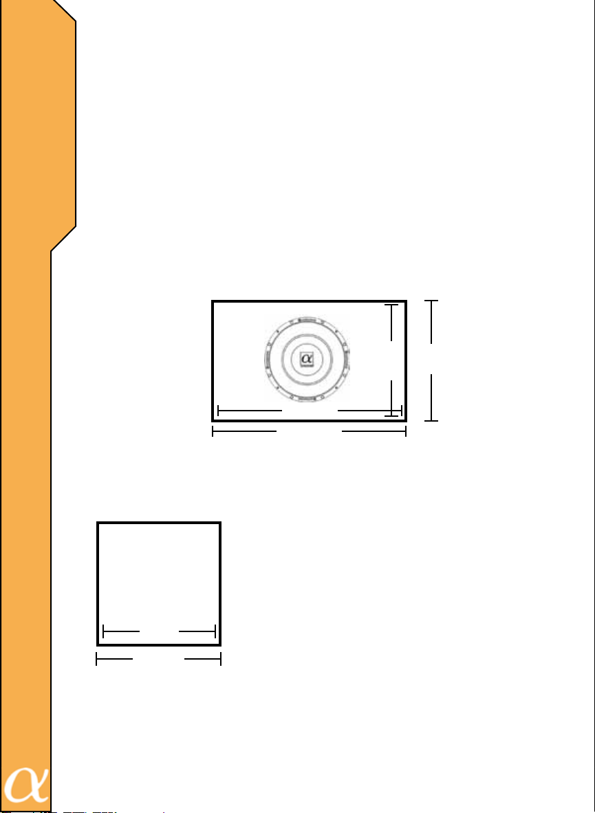
Calculating speaker enclosure volume is a five step procedure.
(Make sure you do not forget to subtract the thickness of the wood that you
I
I
have selected to use to build your enclosure.)
Step One: Measure Height
Step Two: Measure Width
Step Three: Measure Depth
Step Four: Height x Width x Depth
Step Five: Divide the results were in step four by 1728
(12" x 12" x 12"=1728 which equals to 1.0 cu ft.)
Complete formula should look like this
Height x Width x Depth / 1728 =__________
Below are illustrated versions of all the steps that you should take.
(FOR EXAMPLE ONLY)
Step Two
13.5-1.5+12
13.5"
12"
18"
Step One
Step Three
Side View
The wood that we are using is 0.75" thick
The 1.5 that you see in the formula is the thickness
of the wood.
19.5"
Calculating thickness of wood:
Measure how thick the wood is then multiply by two.
The reason that you are multiplying by two is each
side of the enclosure.
Left + Right=1.5
12"
13.5"
13.5-1.5=12
Patent No: US D478,556 S
Patent No: US 6,601,645 B1
7
Patent No: US 6,656,000 B2
Top + Bottom=1.5
Front + Back=1.5
.75 x 2=1.50
18 x 12 x 12=2592
2592 / 1728=1.5
1.5 cu. ft. is the results for this enclosure
Page 9
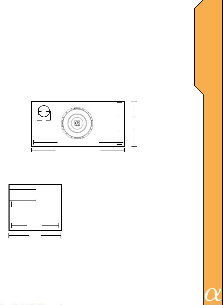
Calculating speaker enclosure volume is a five step procedure.
(Make sure you do not forget to subtract the thickness of the wood and
port displacement that you used.)
Step One: Measure Height
Step Two: Measure Width
Step Three: Measure Depth
Step Four: Height x Width x Depth
Step Five: Divide the results in step four by 1728
(12" x 12" x 12"=1728 which equals to 1.0 cu ft.)
Complete formula should look like this
Height x Width x Depth / 1728 =__________
Below are illustrated versions of all the steps that you should take.
(FOR EXAMPLE ONLY)
4"
4.5"
Step One
Step Three
Side View
7"
13.5"
15"
15-1.5=13.5
Patent No: US D478,556 S
Patent No: US 6,601,645 B1
Patent No: US 6,656,000 B2
12"
21.5"
23"
The wood that we are using is 0.75" thick
The 1.5 that you see in the formula is the thickness
of the wood.
To calculate the thickness of the wood.
Left + Right=1.5
Top + Bottom=1.5
Front + Back=1.5
.75 x 2=1.50
21.5 x 13.5 x 12=3483
3483 / 1728=2.01
2.01 cu. ft. is the result for this enclosure.
Formula to calculate port displacement
3.14 x Radius x Radius x Depth=
________ / 1728=port displacement
3.14 x 2.25 x 2.25 x7=111.27 sq. in.
111.27 / 1728=.06 is the displacement of the port
2.01 - 0.06=1.95 cu.ft. is the final result for this
enclosure.
Step Two
23-1.5=21.5
13.5"
8
B
U
L
D
N
G
A
N
E
N
C
L
O
S
U
R
E
I
I
Page 10
B
U
L
D
N
G
A
N
E
N
C
L
O
S
U
R
E
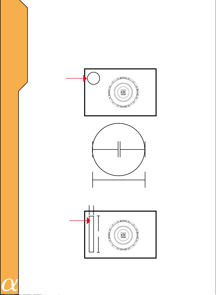
Converting a round port to a slot port.
Calculate the area of the round port(s) being used, then use the square
I
root function of your calculator to get the interior dimensions of an
equivalent suare port. The length (or depth) of the slot port will be the
same as that of the round port.
I
To calculate area: ( Area is a two dimensional measurement )
Circle =3.14 x Radius x Radius
Circle Port
4"
2"
4" Port
2 x 2 x 3.14=12.6
1"
12.6 x 1=12.6
Slot Port
12.6"
Patent No: US D478,556 S
Patent No: US 6,601,645 B1
Patent No: US 6,656,000 B2
9
2"
Page 11
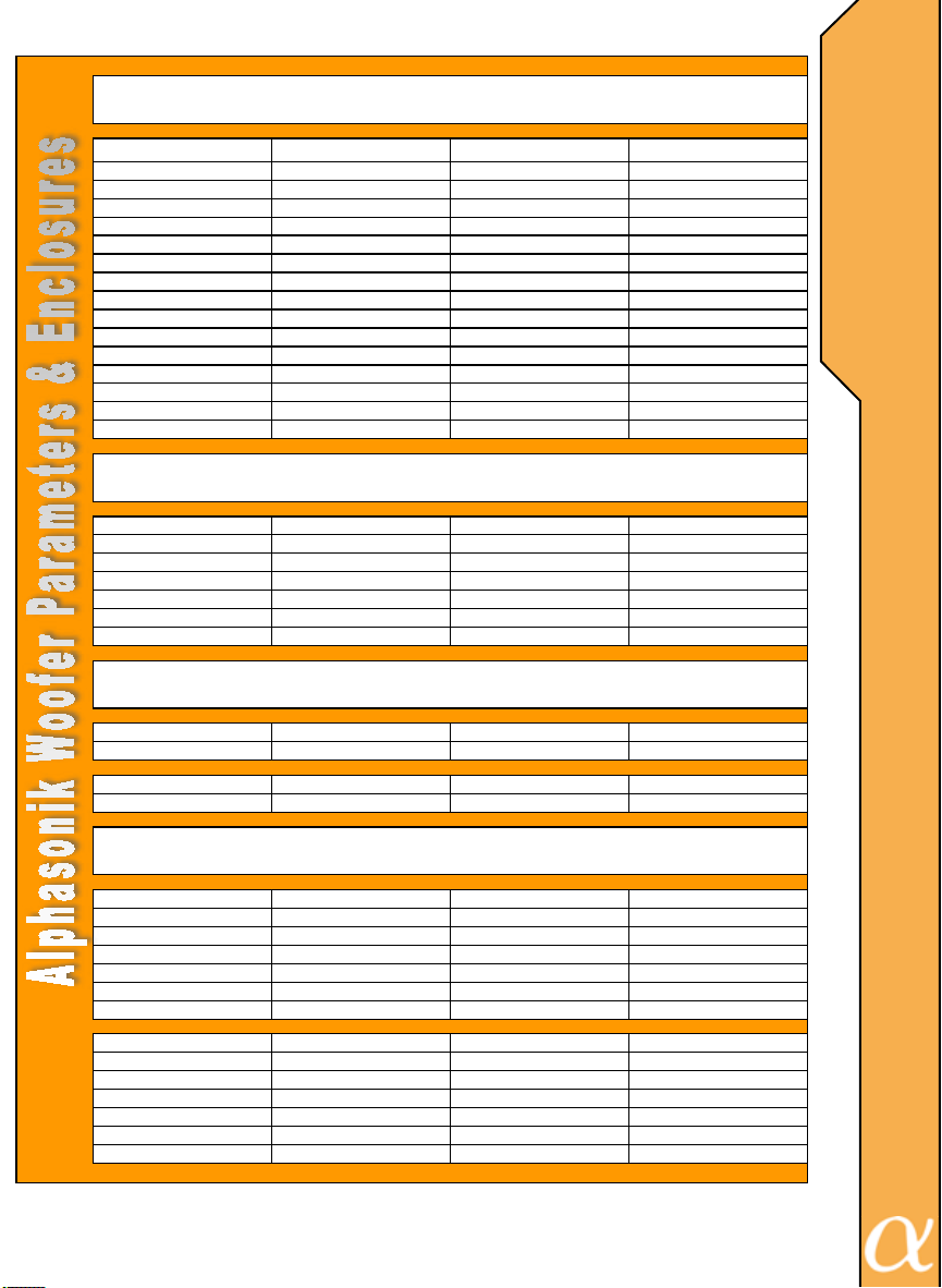
Model # PSW610E PSW612E
Fs 33 28
Vented Enclosures
600 Series
Mounting Dimensions
Sealed Enclosures
Qts 0.47 0.47
Qes 0.5 0.5
Qms 6.1 7.7
Vas (liters) 14 56
Vas (Cu. Ft.) 0.85 2
Re 3.95 x 2 3.4 x 2
Rms 600 700
Xmax +/- (mm) 11 14.5
Le 1.1 2.2
Sd 0.033 0.044
SPL 84.3 86.5
EBP 66 56
Mmd 157 167
Freq. Resp. 33Hz-500Hz 30Hz-500Hz
Depth (mm) 152mm 165mm
Depth (Inches) 6" 6 1/2"
Through Hole (mm) 225mm 276mm
Through Hole (Inches) 8 7/8" 10 7/8"
Diameter (mm) 258mm 312mm
Diameter (Inches) 10 3/16" 12 5/16"
Displacement .137 Cu.Ft. .184 Cu.Ft.
S
U
B
W
O
O
F
E
R
P
A
R
A
M
E
T
E
R
S
Minimum Sealed 0.5 0.85
Sensitivity/dB 85 87
Maximum Sealed 1 1.75
Sensitivity/dB 84 86
Minimum Vented 1.5 2
Internal Volume 1.38 1.79
Port Dia/Inches 4 4
Port Length/Inches 9 8.75
(-3dB) 36 33
Tuning Freq. 45 40
Port Displacement 0.06 0.05
Maximum Vented 2.5 3.5
Internal Volume 2.35 3.16
Port Dia/Inches 4 2x4
Port Length/Inches 8.75 13.25
(-3dB) 29 29
Tuning Freq. 35 35
Port Displacement 0.05 0.18
10
Page 12
W
I
R
I
N
G
D
I
A
G
R
A
M
S
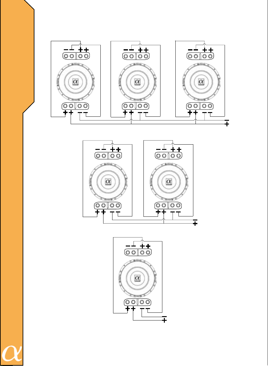
Parallel-Parallel Dual 4 Ohm
0.66 ohms
11
2 ohms
1 ohm
Patent No: US D478,556 S
Patent No: US 6,601,645 B1
Patent No: US 6,656,000 B2
Page 13
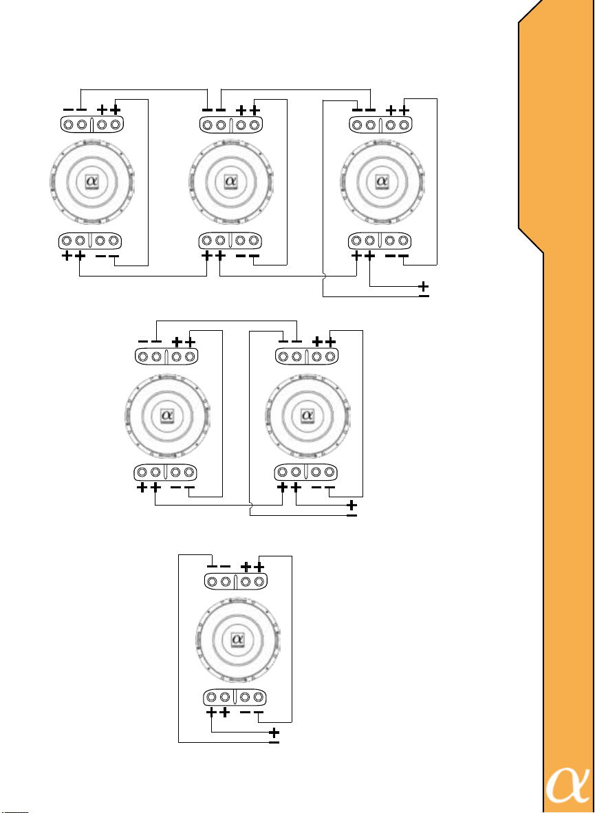
Series-Parallel Dual 4 Ohm
2.67 ohms
W
I
R
I
N
G
D
I
A
G
R
A
M
S
8 ohms
4 ohms
Patent No: US D478,556 S
Patent No: US 6,601,645 B1
Patent No: US 6,656,000 B2
12
Page 14
W
I
R
I
N
G
D
I
A
G
R
A
M
S
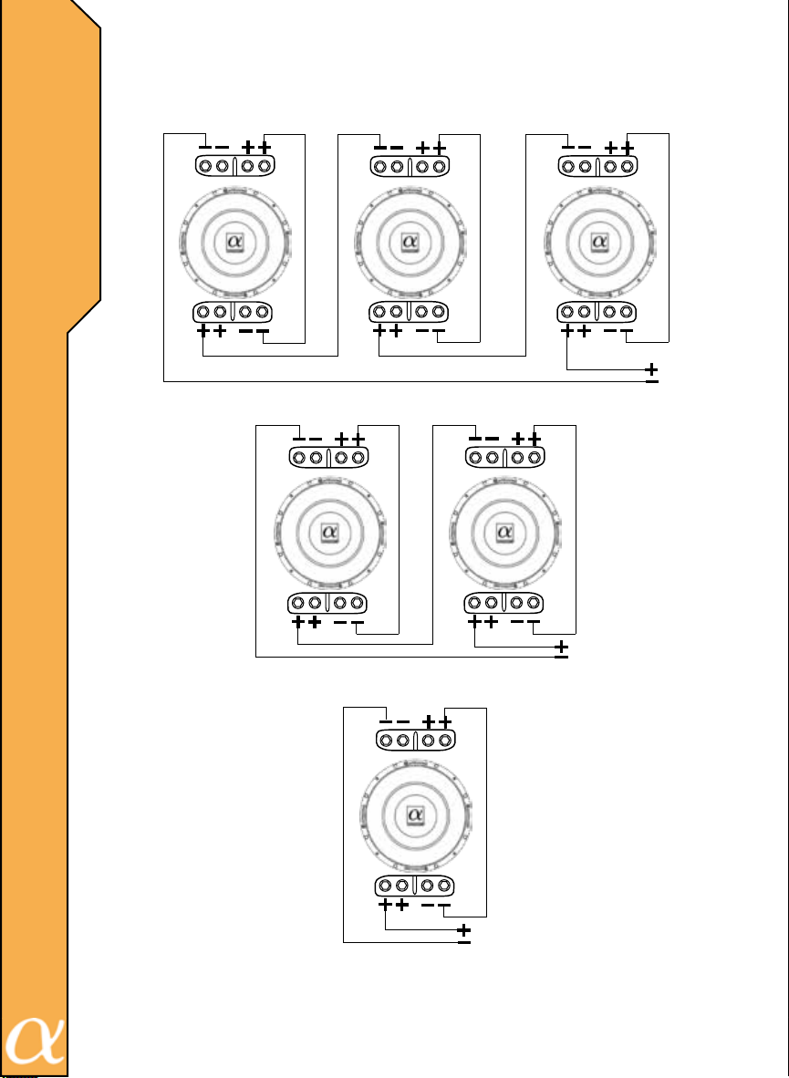
Series-Series Dual 4 Ohm
24 ohms
13
8 ohms
16 ohms
Patent No: US D478,556 S
Patent No: US 6,601,645 B1
Patent No: US 6,656,000 B2
Page 15
T
R
O
U
B
L
E
S
H
O
O
T
N
G
I
14
Page 16

W
A
R
N
I
N
G
A
N
D
D
I
S
C
L
A
I
M
E
R
Investigate the layout of your vehicle thoroughly before
drilling or cutting. Take care when you work near the gas tank,
gas lines, hydraulic lines, electrical components and electrical
wiring. Do not use the equipment unmounted. Attach this system securely to prevent damage, particularly in the event of an
accident or aggressive driving. Do not mount the system so that
wire connections are unprotected or are subjected to pinching
or damage from nearby objects. Before connecting or disconnecting power connections at the system power terminals, disconnect the +12V DC wire at the battery end. Conrm that your
source unit and other equipment are turned off while connecting
the input terminals. If you need to replace the power fuse, replace it only with a fuse identical to the provided fuse. Using a
fuse of different type or rating may result in damage to the system, which is not covered by the manufacturer’s warranty. Do
not install any product where it may be subjected to excessive
heat, moisture and dust or where it may be repeatedly kicked,
brushed or bumped. Make absolutely sure that the terminals
for the products are connected to the proper inputs and outputs
from the music source. Never run the wiring on the outside of
the vehicle or under it where it can be damaged by road hazards
or any moving parts of the vehicle. Use existing wire channels,
sills, panels and molding strips inside the vehicle to hide the wiring for safety and a neat appearance.
15
DISCLAIMER
IMPORTANT: Never cut any metal that is an integral part
of the vehicle’s safety or structural support system. If you are
unsure, it is best to have the product professionally installed by
an Authorized Alphasonik Dealer. Never sacrice your safety for
sound.
Page 17

Alphasonik, Inc. warrants this product against all defects in material and
workmanship for a period of one (1) year from the date of original purchase
provided it was purchased from an Authorized Alphasonik, Inc. Dealer.
The conditions of this warranty and the extent of the responsibility of Alphasonik, Inc. under this warranty are as follows:
1. DATED PROOF OF PURCHASE IS REQUIRED FOR WARRANTY SERVICE OF THIS PRODUCT. Information about Alphasonik, Inc.
authorized warranty service may also be obtained at www.alphasonikinc.com
or by contacting or writing Alphasonik, Inc. at the address listed on the back
of this booklet.
2. This warranty will become void if service is performed by any
one other than an approved Alphasonik, Inc. Warranty Service Center.
3. This warranty does not apply to any product which has been
subjected to misuse, neglect or accident, or which has had the warranty
seal broken, serial number altered, defaced or removed, or which has been
connected, installed adjusted or repaired other than in accordance with the
instructions furnished by Alphasonik, Inc.
4. This warranty does not cover car static, electrical interference,
adjustments or labor costs for the removal or reinstallation of the unit for
repair.
5. The sole responsibility of Alphasonik, Inc. under this warranty
shall be limited to the repair or replacement thereof, at the sole discretion of
Alphasonik, Inc.
6. If it becomes necessary to send the product or any defective
part to Alphasonik, Inc. or an authorized service station, the product must
be shipped in its original or equivalent carton, fully insured, with shipping
charges prepaid. Alphasonik, Inc. will not assume any responsibility for any
loss or damage incurred in shipping.
W
A
R
R
A
N
T
Y
16
Page 18

W
A
R
R
A
N
T
Y
C
O
N
T
I
N
U
E
D
7. This warranty is not transferable and protects the original purchaser provided they reside and made their purchase in the United States.
International consumers may contact their local retailer or distributor for warranty information.
8. ALL IMPLIED WARRANTIES, EXCEPT TO THE EXTENT PROHIBITED BY APPLICABLE LAW, SHALL HAVE NO GREATER DURATION
THAN THE WARRANTY PERIOD SET FORTH ABOVE. UNDER NO
CIRCUMSTANCES SHALL ALPHASONIK INC. BE LIABLE FOR ANY LOSS
OR DAMAGE, DIRECT OR CONSEQUENTIAL, ARISING OUT OF THE
USE OR INABILITY TO USE THE PRODUCT. BECAUSE SOME STATES
DO NOT ALLOW LIMITATIONS ON HOW LONG AN IMPLIED WARRANTY
LASTS OR EXCLUSIONS OR LIMITATIONS OF INCIDENTAL OR CONSEQUENTIAL DAMAGES, THE ABOVE LIMITATIONS OR EXCLUSIONS MAY
NOT APPLY TO YOU.
9. THIS WARRANTY GIVES YOU SPECIFIC LEGAL RIGHTS AND
YOU MAY ALSO HAVE OTHER RIGHTS THAT VARY FROM STATE TO
STATE.
10. Should you have any difculties with the performance of this
product during warranty or with any Alphasonik, Inc. authorized service
center, you may contact the Alphasonik, Inc. National Service Manager at
the address listed on the back of the booklet card or call 714.670.8950 for a
listing of Authorized Warranty Service Centers in your area.
INSTALLED WARRANTY
(When purchased from and installed by an Authorized Alphasonik, Inc.
Dealer)
17
Speaker and Accessories: 1-year over-the-counter defective exchange plus
1-year repair or replacement at the sole discretion of Alphasonik, Inc.
Electronics: 1-year over-the-counter defective exchange, plus 1-year repair
or replacements at the sole discretion of Alphasonik, Inc.
An Alphasonik Extended Warranty Registration Card must be submitted to
Alphasonik, Inc. within 30 days of purchase. To process any warranty claim,
Alphasonik, Inc. will require the dated proof of purchase, which must specically show the model and serial number and that installation was provided
for the product in question. All other terms per Alphasonik, Inc.’s standard
one-year warranty apply.
Page 19

N
O
T
E
S
18
Page 20

ALPHASONIK INC.
7050 VILLAGE DRIVE BLDG. G
BUENA PARK, CALIFORNIA. 90621
TEL: (714)670-8950 · FAX: (714)670-8959
www.alphasonikinc.com
 Loading...