


SERIES 9610
CARBON DIOXIDE ANALYZER
USER MANUAL
Please read this manual before starting to use the Series 9610 Carbon Dioxide Analyzer.
Instructions within the manual are essential for the proper operation of the product.
Alpha Omega Instruments Corp.
40 Albion Road, Suite 100
Lincoln, RI 02865
Phone: 401-333-8580
Fax: 401-333-5550
Website: www.aoi-corp.com
Email: salescontact@aoi-corp.com
CAUTION
Rev 1.0, May 2011
ALPHA OMEGA INSTRUMENTS CORP. ALL
RIGHTS RESERVED INCLUDING THE RIGHT
TO REPRODUCE THIS MANUAL, OR ANY
PORTION THEREOF, IN ANY FORM.

USER MANUAL ALPHA OMEGA INSTRUMENTS CORP
© COPYRIGHT 2011. Alpha Omega Instruments Corp. All rights reserved including the right to
reproduce manual or any portion thereof in any form.
WARRANTY
Alpha Omega Instruments Corp. (Seller) warrants the products delivered to be free from defects in
material and workmanship at the time of delivery to the FOB. point specified in the purchase order, its
liability under this warranty being limited to repairing or replacing, at Alpha Omega Instruments option,
items which are returned to it prepaid within two (2) years from the date of shipment and found to
Seller’s satisfaction to be defective.
Alpha Omega Instruments offers a two (2) year warranty on the carbon dioxide sensor. This warranty
period commences on the date of shipment from Alpha Omega Instruments manufacturing facility.
Any carbon dioxide sensor that fails under normal use must be returned to Seller prepaid and, if such
sensor is determined by Seller to be defective, Seller shall provide Buyer a replacement sensor at no
charge. Buyer must return the Series 9610 Carbon Dioxide Analyzer as the sensor must be replaced
at the factory. If a sensor is found to be defective and a new one issued, the warranty of the
replacement sensor is for a period of one year from the date of shipment. In no event shall Alpha
Omega Instruments Corp. be liable for consequential damages.
NO PRODUCT IS WARRANTED AS BEING FIT FOR A PARTICULAR
PURPOSE AND THERE IS NO WARRANTY OF MERCHANTABILITY.
This warranty applies only if:
(i) the items are used solely under the operating conditions and manner recommended in this
manual, product specifications, or other product specific literature;
(ii) the items have not been misused or abused in any manner or unauthorized repairs were
attempted thereon;
(iii) written notice of the failure within the warranty period is forwarded to Alpha Omega
Instruments Corp. and, the directions received for properly identifying items returned under
warranty are followed;
(iv) the return notice authorizes Alpha Omega Instruments Corp. to examine and disassemble
returned products to the extent the Company deems necessary to ascertain the cause of
failure.
The warranties stated herein are exclusive. THERE ARE NO OTHER WARRANTIES, EITHER
EXPRESSED OR IMPLIED, BEYOND THOSE SET FORTH HEREIN, and Alpha Omega Instruments
Corp. does not assume any other obligation or liability in connection with the sale or use of said
products.
Disclaimer of Warranty
Alpha Omega Instruments Corp. makes no representation or warranties, either expressed or implied, by or with
respect to anything in this manual, including, but not limited to, implied warranties of merchantability or fitness for
a particular purpose. In no event will Alpha Omega Instruments Corp. be liable for any damages, whether direct or
indirect, special, consequential, or incidental arising from the use of this manual. Some states in the USA do not
allow the exclusion of incidental or consequential damages. Alpha Omega Instruments Corp. also reserves the right
to make any changes to improve the performance of its products at any time and without notice.
SERIES 9610 Carbon Dioxide Analyzer PAGE i

ALPHA OMEGA INSTRUMENTS CORP USER MANUAL
This page intentionally left blank
SERIES 9610 Carbon Dioxide Analyzer PAGE ii

USER MANUAL ALPHA OMEGA INSTRUMENTS CORP
Explanation of graphic symbols
The information listed below is essential to the proper operation of the analyzer. Please review the
following safety precautions prior to using the analyzer. Cautionary notes are included throughout this
manual.
THIS SYMBOL IS INTENDED TO ALERT THE USER TO THE PRESENCE OF IMPORTANT
OPERATING AND MAINTENANCE INSTRUCTIONS
THIS SYMBOL IS INTENDED TO ALERT THE USER TO POTENTIALLY DANGEROUS
SITUATIONS OR ITEMS THAT SHOULD BE AVOIDED
Important Safety Information
POTENTIALLY HAZARDOUS AC VOLTAGES EXIST WITHIN THE
DANGER
RISK OF
SHOCK
ANALYZER, IF NOT AVOIDED, COULD POTENTIALLY RESULT IN
DEATH OR SERIOUS INJURY. DISCONNECT ALL SOURCES OF
POWER AND EXTERNAL CONNECTIONS BEFORE REMOVING
THE COVER TO THE ANALYZER
TO AVOID THE RISK OF FIRE OR ELECTRIC SHOCK, DO NOT
EXPOSE THE SERIES 9610 CARBON DIOXIDE ANALYZER TO
RAIN, WATER SPRAY, OR ANY OTHER LIQUIDS.
RF Disclaimer
This instrument generates and uses small amounts of radio frequency energy, and there is no
guarantee that interference will not occur in a particular installation. If this equipment does cause
interference to radio or television reception, try to correct the interference by one or more of the
following steps:
1. Reorient the receiving antenna.
2. Relocate the instrument with respect to the receiver.
3. Change the AC outlet of the instrument so the instrument and receiver are on different
branch circuits.
SERIES 9610 Carbon Dioxide Analyzer PAGE iii

ALPHA OMEGA INSTRUMENTS CORP USER MANUAL
1 Table of Contents
PAGE
Copyright, Warranty, and Disclaimer-------------------i
Explanation of Graphic Symbols, Important Safety
Information, and RF Disclaimer-------------------------iii
Table of Contents-------------------------------------------iv
Tables and Figures-----------------------------------------vii
1 Overview--------------------------------------------------------1
1.1 Instrument Description-----------------------------------------------------------------1
1.1.1 CO2 Sensor----------------------------------------------------------------------------------1
1.1.2 Water Vapor---------------------------------------------------------------------------------1
1.2 Optional Equipment Descriptions--------------------------------------------------2
1.2.1 Low Pressure Regulator-----------------------------------------------------------------2
1.2.2 High Pressure Regulator-----------------------------------------------------------------2
1.2.3 Sample Pump Option---------------------------------------------------------------------2
1.2.4 Particulate Filter----------------------------------------------------------------------------2
1.2.5 Needle Valve--------------------------------------------------------------------------------2
1.2.6 Isolated RS-232 Serial Communications--------------------------------------------2
1.2.7 Isolated RS-485 Serial Communications--------------------------------------------2
1.2.8 Coalescing Filter---------------------------------------------------------------------------2
1.2.9 Data Logger---------------------------------------------------------------------------------3
1.2.10 Flow Meter-----------------------------------------------------------------------------------3
1.2.11 Flow Meter with Integral Valve---------------------------------------------------------3
1.2.12 Bypass Plumbing Assembly------------------------------------------------------------3
1.2.13 Analog Output Isolation------------------------------------------------------------------3
1.2.14 Rack / Panel Mounting Kit---------------------------------------------------------------3
1.3 Standard Features-----------------------------------------------------------------------3
1.4 General Specifications-----------------------------------------------------------------4
2 Installation Procedures------------------------------------5
2.1 Unpacking the Instrument------------------------------------------------------------5
2.2 Electrical Installation-------------------------------------------------------------------5
2.3 Mechanical Configuration-------------------------------------------------------------6
2.4 Wiring Alarm Relays--------------------------------------------------------------------6
2.5 Wiring the mA Outputs-----------------------------------------------------------------7
SERIES 9610 Carbon Dioxide Analyzer PAGE iv

USER MANUAL ALPHA OMEGA INSTRUMENTS CORP
3 Operation-------------------------------------------------------8
3.1 Preparation for Operation-------------------------------------------------------------8
3.1.1 Mounting Configurations-----------------------------------------------------------------8
3.1.2 Initial Check---------------------------------------------------------------------------------8
3.2 Operating Procedures------------------------------------------------------------------8
3.2.1 Power ON------------------------------------------------------------------------------------8
3.2.2 Front Panel Controls and Indicators--------------------------------------------------8
3.3 Navigating the Front Panel and Menu System---------------------------------9
3.3.1 General Navigation------------------------------------------------------------------------9
3.3.2 Pass codes----------------------------------------------------------------------------------9
3.4 Miscellaneous Settings---------------------------------------------------------------10
3.4.1 Setting the Baud Rate------------------------------------------------------------------10
3.4.2 Enabling and Setting Instrument Addresses in Optional RS485------------10
3.4.3 Enabling and Setting the System Software Clock-------------------------------10
3.5 Analog Outputs of the Analyzer---------------------------------------------------11
3.5.1 Setting the Analog Output Range----------------------------------------------------11
3.5.2 Setting the Analog Output Offset----------------------------------------------------11
3.5.3 Analog Output Options Overview----------------------------------------------------12
3.6 Alarm System----------------------------------------------------------------------------12
3.6.1 Setting the Alarm Set point------------------------------------------------------------12
3.6.2 Setting the Alarm High or Low--------------------------------------------------------13
3.6.3 Setting the Alarm Latch-----------------------------------------------------------------13
3.6.4 Setting the Alarm Failsafe-------------------------------------------------------------14
3.6.5 Setting the Alarm Audible--------------------------------------------------------------14
3.6.6 Alarm Options Overview---------------------------------------------------------------14
3.7 Timing Out--------------------------------------------------------------------------------14
4 Sample Gas Handling-------------------------------------15
4.1 Positive Pressure Sampling-------------------------------------------------------16
4.2 Negative Pressure Sampling------------------------------------------------------17
4.3 Gas System Pressure and Flow Limits ----------------------------------------18
4.4 Corrosive Gases------------------------------------------------------------------------19
4.5 Orientation--------------------------------------------------------------------------------19
4.6 Condensible Gas Constituents----------------------------------------------------19
4.7 Sample Filtration-----------------------------------------------------------------------19
SERIES 9610 Carbon Dioxide Analyzer PAGE v

ALPHA OMEGA INSTRUMENTS CORP USER MANUAL
5 Calibration Procedures-----------------------------------20
5.1 Routine Calibration Check----------------------------------------------------------20
5.2 Carbon Dioxide Calibration---------------------------------------------------------20
5.2.1 Procedure for Checking Carbon Dioxide Calibration---------------------------20
5.2.2 Zero Check of the Carbon Dioxide Channel--------------------------------------20
6 Menu System-------------------------------------------------21
6.1 Main Menu--------------------------------------------------------------------------------21
7 Maintenance and Troubleshooting-------------------23
7.1 User Maintenance----------------------------------------------------------------------23
7.2 Serviceable Items----------------------------------------------------------------------23
7.3 Troubleshooting------------------------------------------------------------------------23
8 Optional RS-232/RS-485 Serial Communications.24
8.1 Baud Rates-------------------------------------------------------------------------------24
8.2 Standard Commands------------------------------------------------------------------24
8.3 RS-485 Commands--------------------------------------------------------------------24
8.4 Detailed RS Command Descriptions--------------------------------------------26
8.5 RS-232/485 Connections-------------------------------------------------------------31
Appendix A - Bench Top Configuration Drawings
Part Number BTP------------------------------------------------------------------------32
SERIES 9610 Carbon Dioxide Analyzer PAGE vi

USER MANUAL ALPHA OMEGA INSTRUMENTS CORP
Tables and Figures
Tables
Table 2.1 Relay Configurations-----------------------------6
Table 2.2 Customer Wiring-----------------------------------7
Table 3.5.1 Analog Output Factory Default Settings----11
Table 3.5.2 Overview of Analog Output Settings--------12
Table 3.6.7 Overview of Alarm Settings-------------------14
Table 6.1 Main Menu Settings, Values,
and Descriptions-----------------------------21/22
Table 8.1 Standard RS Commands----------------------25
Figures
Table 8.2 RS-232/485 Wiring------------------------------31
Figure 2.1 Mechanical Dimensions-------------------------5
Figure 2.2 Rear View-------------------------------------------6
Figure 4.1 Simple Positive Pressure Sampling --------15
Figure 4.2 Simple Negative Pressure Sampling
with Internal Pump-------------------------------------------16
Figure 4.3 Positive Pressure Sampling System--------17
Figure 4.4 Negative Pressure Sampling System-------18
SERIES 9610 Carbon Dioxide Analyzer PAGE vii

ALPHA OMEGA INSTRUMENTS CORP USER MANUAL
1 Overview
1.1 Instrument Description
The Series 9610 Carbon Dioxide Analyzer provides an accurate and repeatable measurement of
carbon dioxide in a variety of gas streams. The instrument is powered from a universal power supply
equipped to accept 90-264 VAC, 47-63Hz. Optional equipment includes pressure regulators,
particulate and coalescing filters, and a vacuum pump for conditions when the sample gas lacks
sufficient pressure to move the sample through the instrument's plumbing.
The analyzer is housed in a NEMA 1 equivalent enclosure rated for general purpose indoor use.
Carbon dioxide values are displayed on a 4 line by 20 character liquid crystal display (LCD) with a
total height of 0.81" (20.8 mm). The front panel also includes a membrane panel with seven buttons
that provide access to the analyzer's settings. The instrument is equipped with two alarm relays (see
specifications) which are user configurable and can optionally be set for fail-safe operation. In addition
to the alarm relays, the Series 9610 Carbon Dioxide Analyzer has a built-in audible alarm and two
front panel light emitting diodes (LEDs) for visual indication of an alarm condition. The audible alarm
can be canceled by the user, however the alarm event will still be in effect and indications of the alarm
condition will still be available through the front panel LEDs and relay contact(s). A flow meter is
mounted on the front panel of the instrument and is standard equipment for the Series 9610 Carbon
Dioxide Analyzer. A flow meter with integrated flow control needle valve is available as optional
equipment. The standard Series 9610 Carbon Dioxide Analyzer comes equipped with two direct
current (DC) analog outputs. These analog outputs can be independently configured for 0-20 mA or 420 mA. Both are scalable over the operating range of the instrument's sensor. Using a terminating
resistor on either of these outputs can also provide any analog voltage in the range of 0-10 volts (see
general specifications page for maximum resistance).
1.1.1 CO2 Sensor
The Series 9610 Carbon Dioxide Analyzer uses a non-dispersive infrared (NDIR) sensor to determine
the carbon dioxide concentrations in gases. Infrared gas sensors, which are comprised of solid state
devices, do not chemically react with the gas.
1.1.2 Water Vapor
The Series 9610 Carbon Dioxide Analyzer incorporates a CO2 sensor that uses a high precision
optical system. Therefore, in order to provide accurate and repeatable data, it is essential that the CO
sensor not be exposed to condensed water or other liquids of any type. The dew point temperature of
the sample gas should always be lower than the temperature of the NDIR sensor, thus helping to
prevent the condensation of water vapor on the sensor’s optics. If it is anticipated that the sample gas
may be saturated with water vapor, provisions should be made to remove the water by
filtration/coalescing, refrigeration, vortex cooling, etc. Consult Alpha Omega Instruments Corp. for
more information on this subject.
SERIES 9610 Carbon Dioxide Analyzer PAGE 1
2

USER MANUAL ALPHA OMEGA INSTRUMENTS CORP
1.2 Optional Equipment Descriptions
The Series 9610 Carbon Dioxide Analyzer incorporates standard features that make it immediately
suitable for many applications. However, for certain requirements, the user may desire to augment the
capabilities of the instrument by equipping it with one or more of the available options, as described
below.
1.2.1 Low Pressure Regulator P/N 96-LPR
Aluminum body with a maximum input pressure of 100 PSIG.
1.2.2 High Pressure Regulator P/N 96-PRR
High capacity stainless steel pressure regulator with 3000 PSIG inlet capacity and an adjustable
output pressure range of 0-5 PSIG. Note: Typically used with the optional needle valve (P/N 9NV).
1.2.3 Sample Pump Option P/N 96-PMP
Sample pump designed for applications where the sample pressure is insufficient to transport the
sample gas through the instrument's plumbing.
1.2.4 Particulate Filter P/N 96-95S
Miniature T-type 316 stainless steel filter with 1/4” compression fittings. Recommended when particle
sizes are greater than 5 microns.
1.2.5 Needle Valve P/N 96-NV
Stainless steel needle valve for high pressure sample source (greater than 1 PSIG). Also used in
bypass style plumbing arrangements for applications where the instrument will be used to measure
both positive and negative pressure sources using a sample pump.
1.2.6 Isolated RS-232C Serial Communications P/N 96-RS2
The RS-232C Serial Communications option is installed at the factory and is designed for applications
where enhanced serial communications is required between the Series 9610 Carbon Dioxide Analyzer
and a host system. The maximum distance from the host system is 50 feet.
1.2.7 Isolated RS-485 Serial Communications P/N 96-RS4
The RS-485 Serial Communications option is installed at the factory and is designed for applications
where enhanced serial communications is required between the Series 9610 Carbon Dioxide Analyzer
and a host system over a distance greater than 50 feet. The maximum distance from the host system
is 4000 feet.
1.2.8 Coalescing Filter P/N 96-CF
Filter with aluminum housing. Rated for nominal 0.3 microns (95%).
Spare filter elements for P/N 96-CF. P/N 96-CFE
SERIES 9610 Carbon Dioxide Analyzer PAGE 2

ALPHA OMEGA INSTRUMENTS CORP USER MANUAL
1.2 Optional Equipment Descriptions (continued)
1.2.9 Data Logger P/N 96-DL
Internally mounted four channel data logger (no display). The data logger can be used to record the
CO2 concentrations and operates in a wrap-around mode so that when the memory is full, the oldest
data will be replaced with the newest. Recording frequency is adjustable from once every 0.5 seconds
to once every 9 hours (user selectable). Memory is non-volatile EEPROM with 32,000 readings kept in
storage. Software will be provided that allows downloading of the data to a PC via serial port.
1.2.10 Flow Meter P/N 9FLM
Durable one-piece acrylic flow meter without flow control adjustment. Standard equipment.
1.2.11 Flow Meter with Integral Valve P/N 9FLMC
Durable one-piece acrylic flow meter with flow control adjustment. Optional equipment.
1.2.12 Bypass Plumbing Assembly P/N 9BYPASS
Plumbing arrangement used when the instrument will be used for both positive and negative pressure
source applications. Includes a needle valve and bypass “tee” on the inlet of the instrument. This is
used in conjunction with 9PMP Sample Pump Option. Details are discussed later in the manual.
1.2.13 Analog Output Isolation. P/N 96-IAO
Installed at the factory, galvanic isolation of both analog outputs.
1.2.14 Rack / Panel Mounting Kit P/N 96-RMK
Used for mounting the instrument in either a Rack configuration or inside a panel cutout.
1.3 Standard Features
Analog Outputs: Two 0/4-20 mA, configurable for voltage or direct current
Individually configurable for CO2 monitoring
Maximum load: less than 950 ohms @ 25C
Alarm Relays: Two (2) SPDT Form C contacts rated 10 A (250 VAC) / 5A (100 VDC).
Alarms may be cleared manually or automatically, by user selection.
Individually configurable to be set as high or low alarms for CO2 levels.
Input Power: Universal 90-264 VAC, 47-63 Hz
Audible Alarms: Internal audible alarm (user configurable per alarm)
Audible Alarm Canceling: Individual front panel buttons
Operating Temperature: 50° to 104°F (10° to 40°C) / 99% max humidity (non-condensing)
Enclosure: Aluminum, equivalent to NEMA 1
Enclosure Dimensions: 13 inches (330 mm) – length
11 Inches (280 mm) – width
7 Inches (178 mm ) - height
SERIES 9610 Carbon Dioxide Analyzer PAGE 3

USER MANUAL ALPHA OMEGA INSTRUMENTS CORP
1.4 General Specifications
1
Standard Precision Carbon Dioxide Sensor
Measurement Range2: Percent: 0-20 (standard) / 0-100 (optional)
Trace: 0-5,000 PPM
(determined at order placement)
Resolution: Greater than 10% = 0.1%
Less than 10% = 0.01%
Less than 10,000ppm = 1 ppm
Accuracy: Percent: ±0.5% full scale or ±5% of reading, whichever is
greater
Trace: ±30ppm or ±2% of reading, whichever is greater.
Sensor Type: Non Dispersive Infrared (NDIR)
Recommended Sample
Pressure :
<1.0 PSIG
3
Response Time: < 35 seconds to 63% step change at a sample flow of 0.5
liters per minute
Warm Up Time: < 90 seconds
Sample Flow Rate: 0.1-0.5 liters per minute (SLPM) optimum
Operating Humidity Range: 5-95% RH (non-condensing)
Calibration: Calibration gas
Sample Delivery: Pressure or optional pump
1
All specifications are based on a temperature of 77°F (25°C) at standard pressure of 29.9 inches of mercury
(1 atmosphere).
2
Other ranges for CO2 covering ppm and percent to 100% are available. Please contact the factory for details.
3
The actual pressure of the sample can be much higher, however higher pressure sampling requires different
plumbing arrangements that are described later in the manual.
SERIES 9610 Carbon Dioxide Analyzer PAGE 4

ALPHA OMEGA INSTRUMENTS CORP USER MANUAL
2 Installation Procedures
Figure 2.1 Mechanical Dimensions
2.1 Unpacking the Instrument
Upon opening the shipping container, carefully unpack the instrument to check if the outer surfaces
have been damaged. If so, report the findings immediately to Alpha Omega Instruments who will, in
turn, provide further instructions.
NOTE: IF DAMAGE HAS BEEN FOUND, DO NOT PROCEED
FURTHER, BUT INSTEAD, CONTACT THE FACTORY.
If there is no apparent damage, check the contents to ensure all items were shipped. In some cases,
items may be back ordered. All damage and shortage claims must be made known to Alpha
Omega Instruments within 10 days after receipt of shipment. Carefully rotate the analyzer and
check to make sure no components have been loosened or dislodged. If there are loose or
dislodged components (rattling of any kind), contact the factory for further instructions. If there
is no evidence of loose or dislodged components, the installation procedure can begin.
2.2 Electrical Installation
ELECTRICAL INSTALLATION SHOULD BE PERFORMED BY A
WARNING
The Series 9610 Carbon Dioxide Analyzer is shipped with a standard North American power cord
NEMA style 5-15P. The mating receptacle on the rear panel of the analyzer is an IEC style 60320
C13/C14. The analyzer accepts a power input of 90 VAC to 264 VAC @ 50/60 Hz. There is an On/Off
switch located on the rear of the instrument.
QUALIFIED PERSON AND SHOULD COMPLY WITH
APPLICABLE FEDERAL, STATE, OR LOCAL ELECTRICAL
SAFETY CODES.
SERIES 9610 Carbon Dioxide Analyzer PAGE 5
USER MANUAL ALPHA OMEGA INSTRUMENTS CORP
2.3 Mechanical Configuration
The Series 9610 Carbon Dioxide Analyzer requires no internal configuration and is “ready to use”. The
instrument's cover should not be removed except in rare case to adjust the volume of the internal
pump. Note: carbon dioxide sensors should be replaced at the factory only.
2.4 Wiring Alarm Relays
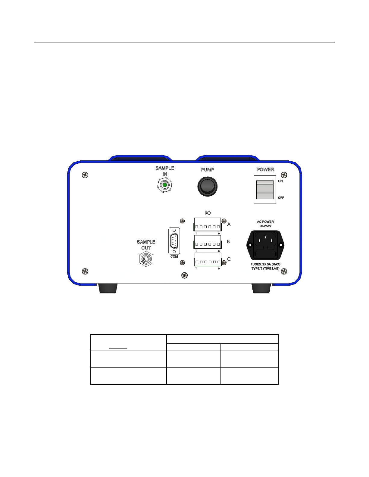
Access to the control signals generated from the Series 9610 Carbon Dioxide Analyzer is
accomplished using the user interface connectors on the rear panel of the analyzer. These connectors
are shown below labeled “I/O”. There are three (3) connectors labeled “A”, “B”, and “C” as shown.
Each connector has 6 pins. Reference Table 2.2 for details on the connector pin outs.
FIGURE 2.2 Rear View
The Series 9610 Carbon Dioxide Analyzer is equipped with two (2) single pole double throw (SPDT)
relays (see specifications). Each alarm relay can be configured by the user, both alarms default to a
factory setting of 0.0 low. To configure the alarm relays, please refer to Section 3.6
Contacts shorted for
each Active Alarm Relay
Alarm 1 / Relay 1
Alarm 2 / Relay 2
TABLE 2.1 RELAY CONFIGURATIONS
TABLE 2.1 illustrates the various wiring configurations for the two alarms in the Series 9610 Carbon
Dioxide Analyzer based on whether the alarms are going to be configured for fail-safe or non fail-safe
operation.
SERIES 9610 Carbon Dioxide Analyzer PAGE 6
Fail-safe ON Fail-safe OFF
NC (C-3) to
COM (C-1)
NC (C-6) to
COM (C-4)
Alarm ON
NO (C-2) to
COM (C-1)
NO (C-5) to
COM (C-4)

ALPHA OMEGA INSTRUMENTS CORP USER MANUAL
2.5 Wiring the mA Outputs
The Series 9610 Carbon Dioxide Analyzer is equipped with two (2) analog outputs, both of which can
be set to either 0-20 mA or 4-20 mA from the front panel. In addition, each of the two analog outputs
can be scaled over a user selectable range. Reference Table 2.2 below to wire one or both of the mA
output(s).
Terminal-Pin # Description Notes
A-1
A-2
A-3
A-4
A-5
A-6
B-1 Analog Output 1 0/4-20 mA
B-2 Analog Output 1 Return
B-3 Analog Output 2 0/4-20 mA
B-4 Analog Output 2 Return
B-5
B-6
C-1 Alarm 1 Common Contact
C-2 Alarm 1 Normally Open Contact
C-3 Alarm 1 Normally Closed Contact
C-4 Alarm 2 Common Contact
C-5 Alarm 2 Normally Open Contact
C-6 Alarm 2 Normally Closed Contact
Reserved for Future Use Do not connect
Reserved for Future Use Do not connect
TABLE 2.2 Customer Wiring
Notes:
1. Do not connect anything to the unused outputs of the analyzer.
2. For voltage outputs, choose the 0-20 mA option. First determine the desired voltage
output. For this example we selected a range of 0-5 volts. Take the 5V and divide it by 20
mA (0.020). This yields a resistance of 250 ohms which is the resistance necessary to
terminate the analog output to obtain a 0-5 volt full scale output. Please remember that
the maximum resistance across the output (including the wiring) is nominally 950 ohms.
SERIES 9610 Carbon Dioxide Analyzer PAGE 7

USER MANUAL ALPHA OMEGA INSTRUMENTS CORP
3 Operation
3.1 Preparation for Operation
3.1.1 Mounting Configurations
Bench Top / Portable (BTP Configuration) The BTP is the basic configuration for the Series 9610
Carbon Dioxide Analyzer, designed for either bench top or portable applications. All gas and electrical
connections are located on the instrument's rear panel. See Appendix A for detailed dimensional
drawings.
Optional Rack / Panel Mounting (RMK Configuration) The RMK is a “Rack Mount Kit” that allows
the instrument to be mounted on an aluminum frame suitable for either rack or panel mounting.
Remote Sensor (RMT) The RMT option allows for a remotely located sensor mounted in it's own
enclosure.
Bench Top / NEMA 7 Explosion Proof Enclosure (BTPX) Benchtop electronics with NEMA 7
explosion proof enclosure
3.1.2 Initial Check
The Series 9610 Carbon Dioxide Analyzer is ready to be used out of the shipping container. The
analyzer has been calibrated at the factory and re-calibration is not required at initial start up1. Please
refer to Section 5.1 for details regarding routine calibration.
3.2 Operating Procedures
3.2.1 Power ON
Power to the instrument is applied when the power cord is plugged into an AC outlet and the power
switch on the rear of the instrument is switched ON. The Series 9610 Carbon Dioxide Analyzer has
non-volatile flash memory so that all the values set by the user via the front panel will be maintained.
Upon powering the Series 9610 Carbon Dioxide Analyzer, the instrument will show “warming up...” to
indicate that it will begin showing the carbon dioxide levels as soon as the carbon dioxide sensor has
warmed up. This will only take a minute or so. This first screen is called the “Home” screen.
3.2.2 Front Panel Controls and Indicators
The front panel of the Series 9610 Carbon Dioxide Analyzer contains a 4 Line liquid crystal display
(LCD), seven (7) membrane panel buttons (“Alarm 1”, “Alarm 2”, up, down, left, right, and “Enter”) ,
and two (2) alarm LEDs. An audible indicator is located inside of the instrument. The 4 Line LCD
display shows the concentration of carbon dioxide in the sample being measured in terms of percent
or ppm carbon dioxide by volume and also displays messages or alerts from the microprocessor. After
the analyzer is powered on and the carbon dioxide sensor warms up, the Series 9610 Carbon Dioxide
Analyzer will immediately begin to measure and display the carbon dioxide concentration of the
sample gas being exposed to the sensor.
Note: For optimum results, the analyzer should be powered on for at least 20 minutes prior to all
calibrations. The sample gas should also be flowing for at least 5 minutes prior to calibration.
1
High precision sensors are compensated, however if using a standard type sensor at higher elevations, it may
become necessary to recalibrate. Please refer to section 5.1 for details on calibration.
SERIES 9610 Carbon Dioxide Analyzer PAGE 8

ALPHA OMEGA INSTRUMENTS CORP USER MANUAL
The Series 9610 Carbon Dioxide Analyzer alarms are set at the factory as low alarms1. Each of the
alarms can be set by the user for operation as high or low alarms. Please refer to Section 3.6 (Alarm
System) for instructions on how to set the alarms.
3.3 Navigating the Front Panel and Menu System
3.3.1 General Navigation
The Series 9610 Carbon Dioxide Analyzer has four distinct display screens. The "Home" screen
displays the sensor values. The “Message” screen displays sensor status information. The “Alarm
status” screen displays the status of the selected alarm. The “Main Menu” screen displays all the
available user adjustable parameters available on the instrument in an easy to use scrollable menu
system using the front panel buttons.
The "Home" screen is a read only screen, there are no adjustable parameters on this screen. This
screen displays the output of each sensor in the instrument.
The “Message” screen is a read only screen, there are no adjustable parameters on this screen. This
screen displays information related to the sensor status. Use the left and right buttons to navigate
between the “Home” and “Message” screens. This screen will display either “A T T E N T I O N !”
when a message is displayed, or “N O A L E R T S” when the sensor status is normal.
The “Alarm Status” screen displays the status of each alarm. The “Alarm Status” screen is accessed
by pressing either the Alarm 1 button or the Alarm 2 button while viewing the “Home” screen. Each
status screen will display only the information relevant to that particular alarm. Pressing the alarm
button a second time while viewing the “Alarm Status” screen will exit the "Alarm Status" screen and
return the user to the "Home" screen. Pressing the Enter button while in the “Alarm Status” screen will
display the alarm settings within the “Main Menu”, allowing the user to change the alarm parameters.
The “Main Menu” screen displays all of the user adjustable options available on the instrument. To
enter the “Main Menu”, while on the "Home" screen, press the Enter button. Use the up and down
buttons to navigate the menu. Using the left and right buttons will navigate between the “Main Menu”'s
main headings, allowing for quicker navigation of the menu. To change a parameter in the menu, use
the up or down button to navigate to the parameter and then press the Enter button to enter into edit
mode for that parameter. The cursor will blink while in edit mode. Use the up, down, left, and right
buttons to edit the parameter value. When finished, press the Enter button to store the new parameter
value or press either the Alarm 1 or Alarm 2 button to cancel all changes and return to the “Main
Menu”. To exit the menu, use the up or down buttons to navigate to one of the “ **EXIT** ” options
and press the Enter button, or simply press either the Alarm 1 or Alarm 2 button while not in edit
mode.
3.3.2 Pass codes
There are 2 pass code levels in the “Main Menu”. Each pass code level will block out all menu options
below that particular pass code. “Pass code #1:” determines access to the Alarm and Analog Output
settings as well as access to “Pass code #2”. “Pass code #2:” determines access to the Calibration
settings. These pass codes are a simple way to hide items that should not be inadvertently changed.
The pass codes are set at the factory to the following:
Pass code #1: 96
Pass code #2: 2642
1
Alarms are disabled at the factory by setting each alarm to be a “low alarm” and setting each set point to zero.
SERIES 9610 Carbon Dioxide Analyzer PAGE 9

USER MANUAL ALPHA OMEGA INSTRUMENTS CORP
The pass codes when shipped from the factory are set as shown above and enables complete access
to the entire menu. Changing these pass codes to any other number than shown above will hide the
menu items below each corresponding pass code. To show the menu items again, simply set the
corresponding pass code back to the factory setting as shown above.
3.4 Miscellaneous Settings
The Series 9610 Carbon Dioxide Analyzer has basic system settings available for the user to edit.
These settings include the baud rate for RS-232/485 communication (optional), addressing for RS-485
communications (optional), and setting or enabling/disabling of the internal software clock.
3.4.1 Setting the Baud Rate
Enter into the “Main Menu” by pressing the Enter button while on the "Home" screen. Navigate the
menu until you reach the menu heading “Misc Settings”. Under the “Misc Settings” heading there is a
list of parameters. Navigate to the “Baud Rate” parameter and press the Enter button to edit the
parameter. This parameter can be set for 2400, 4800, 9600, 19.2K, 28.8K, 38.4K, 57.6K, or 115.2K.
When finished, press the Enter button to save this parameter or press either the Alarm 1 or Alarm 2
button to cancel all changes.
Note: The baud rate will change immediately, therefore any communications equipment
connected to the RS-232/485 output should also be set accordingly to continue communicating
correctly and avoid garbled data.
This option may not be available if the instrument is not ordered with serial communications.
3.4.2 Enabling and Setting Instrument Addresses in Optional RS-485
Enter into the “Main Menu” by pressing the Enter button while on the "Home" screen. Navigate the
menu until you reach the menu heading “Misc Settings”. Under the “Misc Settings” heading there is a
list of parameters. Navigate to the “Addressing?” parameter and press the Enter button to edit the
parameter. This parameter can be set for either “ON” or “OFF”. When finished, press the Enter button
to save this parameter or press either the Alarm 1 or Alarm 2 button to cancel all changes. When the
“Addressing?” parameter is set to ON, the parameter “Address” will appear under the menu heading
“Misc Settings”. To change the instrument's RS-485 communications address, navigate to the
“Address” parameter and press the Enter button to edit the parameter. The address can be set to any
number from 1 to 32. Using the instrument address feature will allow the connection of multiple
instruments onto a single RS-485 communications bus. Up to 32 instruments can be connected with
it's own unique address. For more information see section 8 Optional RS Serial Communications.
This option may not be available if the instrument is not ordered with RS-485 serial communications
3.4.3 Enabling and Setting the System Software Clock
Enter into the “Main Menu” by pressing the Enter button while on the "Home" screen. Navigate the
menu until you reach the menu heading “Misc Settings”. Under the “Misc Settings” heading there is a
list of parameters. Navigate to the “Display Clock?” parameter. Here you can optionally turn the clock
“ON/OFF”. Turning the clock “OFF” will remove the clock from the “Home” screen as well as the menu
options for hours, minutes, and seconds. Turning it “ON” will display the clock on the “Home” screen
and display the menu options for hours, minutes, and seconds. To set these parameters, simply
continue to navigate down to the “Hours”, “Minutes”, or “Seconds” parameter and press the Enter
button to edit the parameter. Use the up and down buttons to change this parameter. Hours can be set
SERIES 9610 Carbon Dioxide Analyzer PAGE 10

ALPHA OMEGA INSTRUMENTS CORP USER MANUAL
for 0-23, minutes can be set for 0-59, and seconds can be set for 0-59. When finished, press the Enter
button to save this parameter or press either the Alarm 1 or Alarm 2 button to cancel all changes.
3.5 Analog Outputs of the Analyzer
The Series 9610 Carbon Dioxide Analyzer is equipped with two (2) standard, non-isolated, analog
outputs (isolated analog outputs are available as options). Each output can be selected to operate
over any range of the carbon dioxide sensor. The analog outputs can be set to correspond to a
custom low to high range within the measurement range of the sensor. The standard analyzer is
shipped from the factory as shown below:
Output Associated Sensor
“Type”
Analog Output 1
Analog Output 2
Carbon dioxide “CO2”
Carbon dioxide “CO2”
Table 3.5.1 Analog Output Factory Default Settings
Analog Output Scaling
(typical settings)
0 to full scale (0 to 20%)
(0 to 5,000 ppm)
0 to full scale (0 to 20%)
(0 to 5,000 ppm)
1
mA Offset
Setting
4-20
4-20
The analog output offset settings determine whether the associated current output is 0-20 mA or 4-20
mA (“live” zero). The “live” zero allows equipment monitoring the current loop to know that something
is wrong when the current falls below 4 mA. The 0 mA setting on the other hand allows for easy
scaling when using a resistor to convert the current to a voltage. These options provide great flexibility
in controlling the range of the analog outputs (See specifications for maximum load resistance).
3.5.1 Setting the Analog Output Range
Enter into the “Main Menu” by pressing the Enter button while on the "Home" screen. Navigate the
menu until you reach the menu heading “Analog Out 1” (or “Analog Out 2”). Under the “Analog Out #”
heading there is a list of parameters, navigate to the “Scale High” parameter and press the Enter
button to edit the parameter. Use the up, down, left, and right buttons to change this parameter for any
number between the value of the “Scale Low” Parameter and the maximum operating range of the
sensor type selected. This parameter represents the sensor value at which the analog output will be at
its highest (20 mA). When finished, press the Enter button to save this parameter or press either the
Alarm 1 or Alarm 2 buttons to cancel all changes. Navigate to the “Scale Low” parameter and press
the Enter button to edit the parameter. Use the up, down, left, and right buttons to change this
parameter for any number between the value of the “Scale High” parameter and zero. “Scale Low”
represents the sensor value at which the analog output will be at its lowest (0 mA or 4 mA depending
on the output's “Offset” setting). When finished, press the Enter button to save this parameter or press
either the Alarm 1 or Alarm 2 button to cancel all changes.
NOTE: The “Scale High” value cannot be set lower than the “Scale Low” value. Likewise, the “Scale
Low” value cannot be set higher than the “Scale High” value. If you are unable to adjust either
parameter to the desired value, check that the other parameter's value is not interfering.
3.5.2 Setting the Analog Output Offset
Enter into the “Main Menu” by pressing the Enter button while on the "Home" screen. Navigate the
menu until you reach the menu heading “Analog Out 1” (or “Analog Out 2”). Under the “Analog Out #”
heading there is a list of parameters, navigate to the “Offset” parameter and press the Enter button to
1
Other ranges for CO2 covering ppm and percent to 100% are available. Please contact the factory for details.
SERIES 9610 Carbon Dioxide Analyzer PAGE 11

USER MANUAL ALPHA OMEGA INSTRUMENTS CORP
edit the parameter. Use the up and down buttons to change this parameter to either 0 mA or 4 mA.
When finished, press the Enter button to save this parameter or press either the Alarm 1 or Alarm 2
button to cancel all changes.
NOTE: Regardless of how the analog outputs are scaled, the analyzer will always maintain the
capability of displaying sensor concentrations over the instrument’s sensor range. Scaling the outputs
does not scale the front panel digital display. Furthermore, sensor alarm relays can be expected to
change state if the sensor values exceed the alarm setting (independent of the output scaling).
3.5.3 Analog Output Options Overview
Below is an overview with a brief description of each option for the Analog Outputs:
Option Description
Scale High Select the high end of the analog output (example: 20.0 %)
Scale Low Select the low end of the analog output (example: 0.00 %)
Offset Select the analog output to be either 0-20 mA or 4-20 mA
Table 3.5.2 Overview of Analog Output Settings
3.6 Alarm System
The Series 9610 Carbon Dioxide Analyzer is equipped with two (2) single pole double throw (SPDT)
relays (see specifications). All alarm relays are user configurable with the front panel controls of the
instrument. When an alarm event takes place, several indications are provided by the Series 9610
Carbon Dioxide Analyzer.
1. The front panel LED associated with the alarm in question will illuminate.
2. An audible alarm will sound (if not disabled by the user via the “Main menu”).
3. The relay associated with the alarm in question will change state.
The alarms are associated with the carbon dioxide sensor in the instrument. Both alarms have
user selectable set points as well as high and low triggers for the set points. The alarms have the
ability to latch if an alarm condition has occurred. A latched alarm requires that the user manually
clear the alarm indication if the alarm condition no longer exists. The alarms can be placed into
fail-safe (“ON” mode) in which the associated alarm relays will be energized in a non-alarm
condition and the associated alarm relays will NOT be energized in an alarm condition. This would
be the same relay state (not energized) that would be achieved if the power source were
interrupted. The factory default fail-safe setting is "OFF". The user also has the option to disable
the built in audible alarm for each individual alarm.
3.6.1 Setting the Alarm Set point
Enter into the “Main Menu” by pressing the Enter button while on the "Home" screen or press the
associated Alarm button on the front panel and press the Enter button while in the "Alarm Status"
screen. Navigate the menu until you reach the menu heading “Alarm 1” (or “Alarm 2”). Under the
“Alarm #” heading there is a list of parameters, navigate to the “Set point” parameter and press the
Enter button to edit the parameter. Use the up, down, left, and right buttons to change this
parameter to any value within the operating limits of the selected sensor type. Press the Enter
button to save this parameter or press either the Alarm 1 or Alarm 2 button to cancel all changes.
SERIES 9610 Carbon Dioxide Analyzer PAGE 12

ALPHA OMEGA INSTRUMENTS CORP USER MANUAL
3.6.2 Setting the Alarm High or Low
Enter into the “Main Menu” by pressing the Enter button while on the "Home" screen or press the
associated Alarm button on the front panel and press the Enter button while in the "Alarm Status"
screen. Navigate the menu until you reach the menu heading “Alarm 1” (or “Alarm 2”). Under the
“Alarm #” heading there is a list of parameters, navigate to the “HI/LO” parameter and press the
Enter button to edit the parameter. This parameter can be set for high “HI”, meaning when the
sensor value is greater than or equal to the set point the alarm will activate, or the parameter can
be set for low “LO”, meaning when the sensor value is less than the set point, the alarm will
activate. Press the Enter button to save this parameter or press either the Alarm 1 or Alarm 2
button to cancel all changes. Note: To disable an alarm, simply set it's “Set point” value to “0.00”
and the “HI/LO” setting to “LO”.
3.6.3 Setting the Alarm Latch
Enter into the “Main Menu” by pressing the Enter button while on the "Home" screen or press the
associated Alarm button on the front panel and press the Enter button while in the "Alarm Status"
screen. Navigate the menu until you reach the menu heading “Alarm 1” (or “Alarm 2”). Under the
“Alarm #” heading there is a list of parameters, navigate to the “Latching” parameter and press the
Enter button to edit the parameter. This parameter can be set for “ON” or “OFF”. Press the Enter
button to save this parameter or press either the Alarm 1 or Alarm 2 button to cancel all changes.
When the “Latching” parameter is set to “ON”, the user is required to manually clear the alarm
indication even if the alarm condition no longer exists. To clear the alarm manually, enter into the
“Main Menu” by pressing the Enter button while on the "Home" screen or press the associated
Alarm button on the front panel and press the Enter button while in the "Alarm Status" screen.
Navigate the menu until you reach the menu heading “Alarm 1” (or “Alarm 2”). Under the “Alarm #”
heading there is a list of parameters, press the Enter button to enter edit mode on any of the
associated alarm parameters. Either edit or confirm the present parameter value to clear the
latched alarm state.
For Example: Alarm 1 is set for a value of 2% high. The carbon dioxide sensor detects a rise in
the carbon dioxide value and the alarm condition is met, triggering Alarm 1. The carbon dioxide
value later returns to a value below 2%. At this time the alarm indication is still active because it
has been latched. Pressing the Alarm 1 button will enter into the “Alarm 1 Status” screen,
displaying that the alarm indication is on. The user must now access the “Alarm #” parameters in
the “Main Menu” and enter into edit mode on any of the associated alarm parameters and either
confirm or edit the value of the parameter to clear the latched alarm state. Note: If the alarm
condition is still valid and an attempt is made to reset the alarm, the alarm will not be reset and will
continue to be active. The audible alarm can optionally be muted while waiting for the alarm
condition to clear by simply pressing the associated Alarm button while viewing the alarm status
from the “Alarm Status” screen (see section 3.6.5 Setting the Alarm Audible).
When the “Latching” parameter is set to “OFF”, the alarm indication will clear whenever the alarm
condition no longer exists.
For Example: Alarm 1 is set for at a value of 2% high. The carbon dioxide sensor detects a rise in
the carbon dioxide value and the alarm condition is met, triggering Alarm 1. The carbon dioxide
value later returns to a value below 2%. At this time all alarm indications will clear because the
alarm “Latching” parameter is set to “OFF”.
SERIES 9610 Carbon Dioxide Analyzer PAGE 13

USER MANUAL ALPHA OMEGA INSTRUMENTS CORP
3.6.4 Setting the Alarm Failsafe
Enter into the “Main Menu” by pressing the Enter button while on the "Home" screen or press the
associated Alarm button on the front panel and press the Enter button while in the "Alarm Status"
screen. Navigate the menu until you reach the menu heading “Alarm 1” (or “Alarm 2”). Under the
“Alarm #” heading there is a list of parameters, navigate to the “FailSafe” parameter and press the
Enter button to edit the parameter. This parameter can be set for “ON” or “OFF”. Press the Enter
button to save this parameter or press either the Alarm 1 or Alarm 2 button to cancel all changes.
With the “FailSafe” parameter set to “OFF”, the alarm relay will energize when there is an alarm
condition. When the “FailSafe” parameter is set to “ON”, the alarm relay will be energized when
there is NO alarm condition.
3.6.5 Setting the Alarm Audible
Enter into the “Main Menu” by pressing the Enter button while on the "Home" screen or press the
associated Alarm button on the front panel and press the Enter button while in the "Alarm Status"
screen. Navigate the menu until you reach the menu heading “Alarm 1” (or “Alarm 2”). Under the
“Alarm #” heading there is a list of parameters, navigate to the “Audible” parameter and press the
Enter button to edit the parameter. This parameter can be set for “ON” or “OFF”. Press the Enter
button to save this parameter or press either the Alarm 1 or Alarm 2 button to cancel all changes.
When set to “ON”, the internal audible alarm will sound when an alarm condition is met. When set
to “OFF”, the internal audible alarm is silenced during an alarm condition.
3.6.6 Alarm Options Overview
Below is an overview with a brief description of each option for the Alarms:
Option Description
Set point Enter the value at which the alarm will activate
HI/LO Select either High or Low level alarm
Latching Select either “ON” or “OFF” for alarm latching
Failsafe Select either “ON” or “OFF” for alarm fail-safe
Audible Select either “ON” or “OFF” for audible alarm
Table 3.6.7 Overview of Alarm Settings
3.7 Timing Out
If the user has navigated to any of the instrument screens other than the "Home" screen in the Series
9610 Carbon Dioxide Analyzer and no navigation has been made for approximately 2 minutes, the
analyzer will automatically revert back to displaying the "Home" screen on the LCD. Also, if the user is
in the process of adjusting any of the instrument parameters (including calibration), and no adjustment
has been made for approximately 2 minutes, the analyzer will automatically revert back to displaying
the "Home" screen on the LCD. When the instrument times out while setting a parameter, the
parameter value will revert to that which was previously set. This is equivalent to canceling any input
by pressing the Alarm 1 or Alarm 2 button. This feature helps to prevent the user from inadvertently
keeping the analyzer off-line for a prolonged period of time or changing a parameter to an undesirable
value.
SERIES 9610 Carbon Dioxide Analyzer PAGE 14

ALPHA OMEGA INSTRUMENTS CORP USER MANUAL
4 Sample Gas Handling
The standard Series 9610 Carbon Dioxide Analyzer has 1/4” quick connect sample gas fittings on the
input and output. Stainless steel 1/4” compression fittings are also available as an option. A standard
Series 9610 Carbon Dioxide Analyzer is shown in Figure 4.1 for use where the flow control will be
done external to the analyzer with either a pressure regulator and/or needle valve. To the right shows
the optional flow meter with integrated flow control which allows for higher pressure at the input.
Standard Series 9610 Series 9610 with optional flow control
Sample IN Sample IN
< 1 PSIG
Series 9610
Sensor Sample OUT Sensor Sample OUT
Ambient Ambient
Sample Flow Sample Flow
< 1 PSIG
Series 9610
Figure 4.1 Simple Positive Pressure Sampling
It is highly recommended to reduce the pressure of the sample gas to less than 1 PSIG at the
analyzer's input to significantly reduce the risk of damaging the sensor. See the Bypass
Plumbing Assembly option later in the manual for a better plumbing arrangement for sampling
pressurized inputs greater than 1 PSIG.
Note: Particular attention should be paid to ensure that there are no “Sample OUT” restrictions (or
sources of back pressure) connected to the output of the analyzer to avoid pressure related
errors.
In relation to the two standard configurations shown, typically the instrument is operating in one of two
ways:
1. Monitoring a pressure regulated source where the pressure is already controlled to less than
1 PSIG. This may or may not need a flow meter with integral flow control adjustment
depending on the pressure of the sample and whether the control valve is external or not.
2. Drawing a sample from a source (using the optional internal pump). This sample source is
usually at or very close to atmospheric pressure. This configuration can also come with or
without a flow meter with integral flow control adjustment1.
In both cases, the sample gas should be vented out the “Sample OUT” port to an ambient atmosphere
to avoid any back pressure on the sensor.
In Figure 4.2, the optional internal sample pump has been added to the plumbing arrangement. Note
that this configuration is used when drawing a sample gas that is at or near ambient pressure.
1
Depending on the pressure of the sample and whether the control valve is external or not.
SERIES 9610 Carbon Dioxide Analyzer PAGE 15

USER MANUAL ALPHA OMEGA INSTRUMENTS CORP
9610 with optional internal pump
Sample IN
(slight vacuum)
Series 9610
Sensor Sample OUT
Ambient
Pump
Sample Flow
Figure 4.2 Simple Negative Pressure Sampling with Internal Pump
Again, the control on the flow meter is optional depending on the application. For instance, when using
a bypass arrangement as described later in this manual.
4.1 Positive Pressure Sampling
The standard Series 9610 Carbon Dioxide Analyzer does not come equipped with a sample pump. In
this case, the sample must be under positive pressure and the “Sample Flow” must be adjusted by
means of an external flow adjustment or by means of the optional flow adjustment on the front panel
flow meter. As stated earlier, the factory strongly recommends the sample gas to be allowed to vent to
atmosphere to avoid errors in the measurement due to back pressure.
DO NOT draw a sample through the “Sample OUT” exit fitting under vacuum as this could
cause significant errors in the gas measurements.
Figure 4.3 is an example of using the Series 9610 Carbon Dioxide Analyzer in a positive pressure
sampling mode with the capability of using higher than 1 PSIG sample sources.
Please note that in Figure 4.3, the sample source is coming from a pressurized cylinder of gas and is
then routed through a pressure regulator. The regulated sample source output is shown with an arrow
pointing to the “Sample IN” where an optional needle valve may be installed in series in order to
achieve the recommend pressure of 1 PSIG. If the Series 9610 Carbon Dioxide Analyzer is ordered
with a flow meter that does not have an integral flow control adjustment then the needle valve will be
used to control the final pressure drop and therefore the flow rate into the analyzer.
SERIES 9610 Carbon Dioxide Analyzer PAGE 16
ALPHA OMEGA INSTRUMENTS CORP USER MANUAL
9610 with high pressure sample source
Regulator Optional
Needle
1
Valve
Sample IN
Figure 4.3 Positive Pressure Sampling System
Series 9610
Sensor Sample OUT
Ambient
Sample Flow
In some cases the sample gas may be simply routed through a tee at the “Sample IN” and the flow
controlled using either the optional flow meter with integral flow control adjustment or a needle valve
on the “Sample IN”. This is called a “bypass”.
In section “Negative Pressure Sampling” there is a “Bypass Plumbing Assembly” (BPA) that is
available for use when the Series 9610 Carbon Dioxide Analyzer is equipped with a pump and must
draw a sample. This BPA can also be used for “Positive Pressure Sampling” as well. The only
difference is that the pressurized sample gas source is split between the bypass flow and the “Sample
IN” (no pump needed).
As shown in Figure 4.4, there is typically some kind flow restriction or needle valve at the exit of the
bypass to create enough pressure at the “Sample IN” of the analyzer to sample the gas source. See
Figure 4.4 for more details (ignoring the pump).
4.2 Negative Pressure Sampling
The Series 9610 Carbon Dioxide Analyzer can also be ordered with an optional sample pump that is
mounted inside the instrument. Alpha Omega Instruments Corp. strongly recommends using the
optional pump supplied at the factory when drawing a sample from a source at or near atmosphere.
The pump draws a slight vacuum from the “Sample IN” port (maximum of 0.5 atmosphere)2. To adjust
the proper flow rate, use either an external needle valve or the optional Sample Flow adjustment knob
on the front panel flow meter. The instrument should not be used under positive pressures when
equipped with a sample pump unless using a Bypass Plumbing Assembly (as shown in Figure 4.4
below) where the bypass is vented to atmosphere.
Note: This is the recommended calibration procedure when using a cylinder of gas.
1
Typically the needle valve is not necessary. A case where it might be necessary is when the Series 9610 Carbon
Dioxide Analyzer is ordered without a flow meter with integral flow control adjustment. In this case, the needle valve
will be used to control the final pressure drop and therefore the flow rate into the analyzer.
2
This would be an extreme condition and would require the pump volume control inside the analyzer to be adjusted
to maximum
SERIES 9610 Carbon Dioxide Analyzer PAGE 17

USER MANUAL ALPHA OMEGA INSTRUMENTS CORP
Bypass Plumbing
Assembly (BPA)Regulator Ambient
Sample OUT
Pressurized
Regulated
Sample Source
Sensor
Ambient
Pump
Sample Flow
Series 9610
Figure 4.4 Negative Pressure Sampling System
Note: The use of the Bypass Plumbing Assembly allows the analyzer to sample at much higher
sample pressure inputs. Never connect a vacuum source to the gas outlet of the Series 9610.
The vacuum pump inside the instrument is factory set for enough flow to draw a sample from at or
about ambient. This can be adjusted if necessary (never dead end the pump as excessive vacuum
can damage the sensors). Please contact the factory for any special requirements. For specific
sampling system questions, please contact the factory.
4.3 Gas System Pressure and Flow Limits
Alpha Omega Instrument’s optional sample pump (P/N 9PMP) is designed to provide a sample flow
rate of up to 1.0 standard liter per minute (SLPM). Optimum flow rates are between 0.2 to 0.5 SLPM. If
flow rates are expected to be much higher, it is strongly advised to install a flow control up stream on
the sample inlet. As shown in the previous diagrams, an optional “Bypass Plumbing Assembly” is
available at the time of purchase to accommodate such a situation. For sample gases and/or
calibration gases that are under pressure, it is imperative that the input pressure to the sensor be kept
to under 1.0 pound per square inch (PSIG) or 0.07 kg/cm2. If the pressure is expected to be in excess
of 1.0 PSIG, it is advisable to use a pressure regulator and most likely a needle valve and/or a valved
flow meter. Alpha Omega Instruments offers a pressure regulator (P/N 9LPR) for use up to 100 PSIG
(7.031 kg/cm2). Other regulators with higher capacities are available. Please consult the factory.
SERIES 9610 Carbon Dioxide Analyzer PAGE 18

ALPHA OMEGA INSTRUMENTS CORP USER MANUAL
4.4 Corrosive Gases
It is not recommended that the Series 9610 Carbon Dioxide Analyzer be used when the sample
contains corrosive gas components such as hydrogen sulfide, chlorine, hydrogen fluoride, et. al. If
unsure as to the suitability of the gas components in question, please contact the factory prior to start
up.
4.5 Orientation
The analyzer should be kept in its designed bench top orientation. Do not operate the analyzer in any
position other than level or slightly angled for better viewing with the use of the equipped bail. Using
the bail to tilt the analyzer will not effect the sensor reading, however the flow meter will indicate a
slightly different flow rate due to the design of the flow meter, this is normal. In general, the Series
9610 Carbon Dioxide Analyzer is not flow sensitive.
4.6 Condensible Gas Constituents
The Series 9610 Carbon Dioxide Analyzer should not be used for applications where there is a
likelihood that one or more gas constituents will condense (liquefy). Usually, sample gases with high
dew point temperatures (water vapor concentration) can pose a problem. If the sample gas
temperature is allowed to cool to the dew point temperature of the sample gas, condensation will take
place. If the sensor is exposed to liquids, even in small amounts, erroneous readings will occur and
there may be permanent damage to the sensor. A water trap or absorbent system can be used to
eliminate the condensate for some applications. Please consult the factory for additional assistance.
4.7 Sample Filtration
As a general cautionary note, if the sample gas contains gas borne particles, filtration of the sample is
required. Contact the factory for specific recommendations. Damage to the sensor due to gas borne
particulates is not covered under warranty.
SERIES 9610 Carbon Dioxide Analyzer PAGE 19

USER MANUAL ALPHA OMEGA INSTRUMENTS CORP
5 Calibration Procedures
All Series 9610 Carbon Dioxide Analyzers have been fully calibrated at the factory prior to shipment.
Alpha Omega Instruments gas measuring sensors feature high accuracy and excellent long term
stability characteristics.
5.1 Routine Calibration Check
Routine maintenance is kept to a minimum. As is the case with all gas analyzers and monitors, it is
advisable to periodically check the overall system calibration. The frequency of these checks is often
determined by in-house calibration protocols. If none exists, Alpha Omega Instruments Corp.
recommends that a calibration check be made on average once every 4-6 months. Individual
calibration procedures are detailed on the following pages.
5.2 Carbon Dioxide Calibration
To check the calibration of the Series 9610’s carbon dioxide sensor, a cylinder of calibration gas will
be required. The carbon dioxide content of the cylinder should be within approximately 60-90% of the
full scale range of the carbon dioxide sensor. When ordering the calibration gas from a supplier,
specify the carbon dioxide range desired and specifying the balance of the gas as nitrogen. Follow the
procedure below for calibration.
5.2.1 Procedure for Checking Carbon Dioxide Calibration
1. Select a cylinder of calibration gas as described above. When selecting a pressure regulator to
use with the cylinder gas, it is advisable to use a two-stage regulator with the second stage
capable of delivering a gas sample at a pressure of under 1.0 PSIG. Note: If the analyzer has
an internal pump, then the supplied gas should be through a Bypass Plumbing Assembly with a
length of tubing vented to atmosphere (this is to avoid back diffusion into the sample inlet).
Using a bypass TEE1 will allow the pump to sample the gas at or around atmospheric pressure
and avoid errors in the readings due to pressure variations.
2. Apply power to the Series 9610 Carbon Dioxide Analyzer and set the calibration gas flow rate
to a nominal 0.25 SLPM. Observe the response of the monitor to the calibration gas, waiting (at
least 5 minutes) until a stable reading has been established. (The use of a recorder or data
logger can be very helpful in verifying that the monitor has reached an equilibrium point).
3. If the carbon dioxide value read from the LCD differs from the calibration gas, a calibration
adjustment should be made so the value displayed in the LCD is identical to that of the value of
the calibration gas. Enter into the “Main Menu” by pressing the “Enter” button while on the
"Home" screen. Navigate the menu until you reach the menu heading “Calibrate CO2”. Under
the “Calibrate CO2” heading there are 2 parameters, “CO2 Sensor” and “Cal Value”. “CO
Sensor” is calculated value of carbon dioxide being sampled by the sensor, “Cal Value” is the
value to which the carbon dioxide sensor will be calibrated. To calibrate, navigate to the “Cal
Value” parameter and press the Enter button to edit the “Cal Value” parameter. Use the up,
down, left, and right button to set this parameter to the level of the calibration gas being
sampled by the sensor. Press Enter again to set this value as the new carbon dioxide level.
5.2.2 Zero Check of the Carbon Dioxide Channel
The Series 9610 Carbon Dioxide Analyzer does not require zero adjustment.
2
SERIES 9610 Carbon Dioxide Analyzer PAGE 20

ALPHA OMEGA INSTRUMENTS CORP USER MANUAL
6 Menu System
The menu system is comprised of a simple rotating menu that shows the individual items that can be
set or viewed by the user. There is only one menu - the “Main Menu”.
6.1 Main Menu
The “Main Menu” is where all of the settings will be changed or viewed. The following table shows the
“Main Menu” and the options available. Press the Enter button while in the "Home" screen to display
the “Main Menu” as shown below. Pressing the Enter button on any adjustable parameter will enter
into edit mode. Use the up, down, left, and right buttons to change the parameter values, press the
Enter button to save the new parameter value, or press either the Alarm 1 button or the Alarm 2 button
to cancel all changes. Note: Depending on system configuration, not all options may be available,
such options include “Baud Rate?” and “Addressing?”, available only if RS communications is installed
in the instrument. The “Clock Set” options will only appear if the “Display Clock?” option is turned ON.
Misc Settings Values Description
Baud Rate?
Addressing? ON, OFF Allow RS-485 Addressing
Address 1 to 32 Select RS-485 Communications Address
Display Clock? ON, OFF Turn Clock On/Off
Clock Set Hours: 0-23 Set Clock Hours (Clock ON)
Clock Set Minutes: 0-59 Set Clock Minutes (Clock ON)
Clock Set Seconds: 0-59 Set Clock Seconds (Clock ON)
Passcode #1: XXXXX
----ALARM 1---- Values Description
Set Point: XXX.XX Within limits of instrument sensor range
HI/LO? HI, LO Alarm trigger greater or less than setpoint
Latching? ON, OFF Latching or Non-Latching Alarm
Failsafe? ON, OFF Fail-Safe or Non-Fail-Safe Alarm Relay
Audible? ON, OFF Audible Alarm
----ALARM 2---- Values Description
Set Point: XXX.XX Within limits of instrument sensor range
HI/LO? HI, LO Alarm trigger greater or less than setpoint
Latching? ON, OFF Latching or Non-Latching Alarm
Failsafe? ON, OFF Fail-Safe or Non-Fail-Safe Alarm Relay
Audible? ON, OFF Audible Alarm
2400, 4800, 9600, 19.2K,
28.8K, 38.4K, 57.6K, 115.2K
**EXIT**
**EXIT**
**EXIT**
Table 6.1 Main Menu Settings, Values, and Descriptions
Select Baud Rate for RS-232
Communications
Pass code to allow access to Alarm and
Output options
Continued on Next Page
SERIES 9610 Carbon Dioxide Analyzer PAGE 21

USER MANUAL ALPHA OMEGA INSTRUMENTS CORP
Continued from Previous Page
- Analog Out 1 - Values Description
Scale High: XXX.XX Select High end of custom range for Analog Output within
limits of the sensor
Scale Low: XXX.XX Select Low end of custom range for Analog Output within
limits of the sensor
Offset: 0 mA, 4 mA Select mA Output offset of either 0 mA or 4 mA for 0-20
mA or 4-20 mA
**EXIT**
- Analog Out 2 - Values Description
Scale High: XXX.XX Select High end of custom range for Analog Output within
limits of the sensor
Scale Low: XXX.XX Select Low end of custom range for Analog Output within
limits of the sensor
Offset: 0 mA, 4 mA Select mA Output offset of either 0 mA or 4 mA for 0-20
mA or 4-20 mA
**EXIT**
Passcode #2: XXXXX Pass code to allow access to Calibration Options
- CALIBRATE CO2 -
CO2 Sensor: XXX.XX Calculated carbon dioxide value being sampled by the
Cal Value: XXX.XX Value to Calibrate the carbon dioxide sensor to
Elevation XXXXX Sets instrument elevation
Table 6.1 Main Menu Settings, Values, and Descriptions (continued)
Values Description
sensor
**EXIT**
SERIES 9610 Carbon Dioxide Analyzer PAGE 22

ALPHA OMEGA INSTRUMENTS CORP USER MANUAL
7 Maintenance and Troubleshooting
7.1 User Maintenance
The Series 9610 Carbon Dioxide Analyzer requires minimum user maintenance. The user should
check the calibration of the analyzer in accordance with established protocol. If no protocol exists,
Alpha Omega Instruments recommends that the analyzer be calibrated every 4-6 months.
7.2 Serviceable Items
End user serviceable items located inside the chassis include the optional pump. Do not open the
chassis except in rare cases when the flow rate, by way of the pump, needs adjustment. Please
contact the factory for more information on adjusting the pump/flow rate in special circumstances.
WARNING: ELECTRICAL SHOCK HAZARD: DANGEROUS
VOLTAGES ARE PRESENT WITHIN THE INSTRUMENT. THIS
PARTICULAR WARNING SYMBOL IS SPECIFIC TO AN
WARNING:
RISK OF
SHOCK
ELECTRICAL HAZARD EXISTING AT OR NEARBY THE
COMPONENT AND/OR PROCEDURE UNDER DISCUSSION.
FAILURE TO HEED THE WARNINGS MAY RESULT IN INJURY
AND/OR DEATH. REMOVE ALL POWER SOURCES WHEN
INSTALLING OR REMOVING AC POWER OR DATA SIGNAL
CONNECTIONS AND WHEN PERFORMING ANY WORK INSIDE THE
INSTRUMENT ENCLOSURE.
7.3 Troubleshooting
In the case that readings are incorrect, please consider the following while using the Series 9610
Carbon Dioxide Analyzer:
• Leaks in the sample lines are the most common source of error when it comes to the gas
sample readings. If there are leaks in the sampling system, the readings could display as high
or low depending on the gas concentration being measured. This is due to the fact that there is
typically less than 500 ppm of CO2 in the ambient air. Ambient air, if allowed to leak into the
sampling system ,will cause erroneous readings on the display. For example, if the analyzer is
monitoring a tank of 10% carbon dioxide and there is a leak in the upstream plumbing, the
sensor will be exposed to a portion of the ambient air mixed with the 10% sample and show a
lower reading.
• Another source of error is improperly calibrated sensors. It is recommended to first check the
calibration of the sensor in question before investigating any other source of error.
• Readings on the 4-20 mA outputs may also be incorrectly scaled. Be sure to check the scaling
on the outputs to insure that the range of gas is properly indicating while on a known gas.
Note: using ambient air is a good way to make a quick check of the system. The CO2 should
read close to zero (in the 100 to 300 ppm range).
SERIES 9610 Carbon Dioxide Analyzer PAGE 23

USER MANUAL ALPHA OMEGA INSTRUMENTS CORP
8 Optional RS Serial Communications
8.1 RS-232/485 Baud Rates
RS-232 and RS-485 serial communication baud rates can be set to one of the following: 115200,
57600, 38400, 28800, 19200, 9600, 4800, and 2400.
Enter into the “Main Menu” by pressing the Enter button while on the "Home" screen. Navigate the
menu until you reach the menu heading “Misc Settings”. Under the “Misc Settings” heading there is a
list of parameters. Navigate to the “Baud Rate?” parameter and press the Enter button to edit the
parameter. Use the up and down buttons to change this parameter to any of the available baud rates
listed above. When finished, press the Enter button to save this parameter or press either the Alarm 1
or Alarm 2 button to cancel all changes.
8.2 Standard Commands
This section describes standard RS-232/485 commands. The commands can be entered in either
upper or lower case. Optional strings are case-sensitive, such as naming the instrument with the 'N'
command, or enabling a security password with the 'E' command.
Standard commands are not case-sensitive, such as when setting a parameter to 'on' or 'off'. Letters
may be in either upper or lower case.
The special text: simply denotes pressing the ENTER key on the keyboard.
<Enter>
Table 8.1 on the next page shows the Help screen which is accessed by pressing:
H <Enter>
This screen includes a list of all commands available to the user. Optional command parameters are
shown in brackets for example: [ON|OFF] simply means “ON” or “OFF” as an optional command.
“[string]” is used to denote a string of text to be entered by the user.
Some command have a letter in between brackets. These letters are simply placeholders for a specific
input required for that command. These inputs are listed under “Where:” in Table 8.1. Please see the
details in the table for descriptions of these letter placeholders.
8.3 RS-485 Commands
As noted in the Help screen, instruments equipped with RS-485 communications that have addressing
enabled in the “Main Menu” require the prefix of #[#]: where #[#] is a number between 1 and 32
representing the instrument's address. This address is set in the “Main Menu” using the instruments
front panel controls. For example, to retrieve the status of an instrument with the address of 15, the
command would be:
15:V <Enter>
Similarly, to retrieve the status of an instrument with address 3, the command would be:
3:V <Enter>
The instrument addressing can be enabled or disabled in the “Main Menu”. Instruments with
addressing disabled will respond to commands without the addressing prefix. When addressing is
disabled, only one instrument should be connected to the communications bus.
SERIES 9610 Carbon Dioxide Analyzer PAGE 24

ALPHA OMEGA INSTRUMENTS CORP USER MANUAL
Command Description
Aa=[#[.#]][L|H]
B=[baud]
C=#[.#]
D=[string]
E=[string]
Fd=[ON|OFF]
G[b]
H
La=[ON|OFF]
N=[string]
Oc=[ON|OFF]
Q=[ON|OFF]
Rc=#[.#]L|H
Sa=[ON|OFF]
T=[ON|OFF]
T##:##[:##]
V
Where:
a 1' or '2' for Alarm 1 or Alarm 2
c 1' or '2' for Output Channel Number
d 1' or '2' for Relay 1 or 2
#[.#] Whole or Decimal number
L/H 'L'ow or 'H'igh alarm or output range setting
baud Baud rate number from 2400 to 115200
string String for security protection (see manual)
Notes:
OFF/0 are interchangeable
ON/1 are interchangeable
RS-485 requires a prefix of ##: where ## is 1 to 32 for instrument's address when addressing is enabled
Some models have only one sensor (see manual)
Alarm value set
Baud rate
Calibrate sensor
Disable Security
Enable Security
Fail-safe for Alarm Relays
Get Sensor Output(s)
Help screen (this screen)
Latching/Non-Latching for alarms
Optionally name the instrument
Offset for mA Outputs (ON=4 mA)
Quiet mode (mutes the audible)
Range low|high for mA outputs
Sound audible alarms
Time display
Set clock time in HH:MM:[SS]
View current Alarms and settings
Table 8.1 Standard RS Commands
Single Letter Commands:
All single letter commands, with the exception of 'D' and 'E', will return current status information
related to that command, even when security is enabled. Single letter commands can include a '1' or a
'2' to denote the specific letter placeholder ('a','b','c', and 'd' as noted in the help screen).
For example a single letter command to find out the alarm fail-safe configuration would be:
F <Enter>
The preceding command will return:
Alarm 1: CO2 0.00 % (LO) (Autoreset) (Audible) Failsafe: OFF
Alarm 2: CO2 0.00 % (LO) (Autoreset) (Audible) Failsafe: OFF
SERIES 9610 Carbon Dioxide Analyzer PAGE 25

USER MANUAL ALPHA OMEGA INSTRUMENTS CORP
While
F1 <Enter>
Will return:
Alarm 1: CO2 0.00 % (LO) (Autoreset) (Audible) Failsafe: OFF
The single letter command of 'F' will return the settings for both Alarm 1 and Alarm 2, while 'F1' will
only return the settings for Alarm 1.
8.4 Detailed RS Command Descriptions
'A' Command - Alarm setting
Set the alarm level and high or low trigger.
For example: Alarm #1 will be set to go off in the case of the sensor concentration dropping below 2%.
Type the following:
A1=2.0L <Enter>
To change Alarm #1 to 8% instead of 2% you could type:
A1=8 <Enter>
The low alarm is optional unless changing to high. As you can see, the decimal point is optional too,
and if left out, the digits to the right of the decimal default to '0'. Notice how the command in the help
screen says, "[#[.#]][L/H]"? Examine the following example:
A1=H <Enter>
This is a valid command and will only effect the low or high (H) status of Alarm 1. To set it back to a
low alarm type:
A1=L <Enter>
Single Letter Commands: A A1 A2
'B' Command - Baud Rate.
Set the communications baud rate of the instrument
To change the baud from 57600bps (default) to 38400bps, first establish communication at 57600bps
then type the following:
B=38400 <Enter>
A message will be displayed informing you to change the terminals baud rate. You must change your
terminal's baud rate to reestablish communication with the instrument
Single Letter Commands: B
'C' Command – Calibration
Calibrate the CO2 sensor.
To calibrate the CO2 sensor using a calibration gas consisting of 8.35% CO2/ balance nitrogen as an
example, type the following:
C=8.35 <Enter>
SERIES 9610 Carbon Dioxide Analyzer PAGE 26

ALPHA OMEGA INSTRUMENTS CORP USER MANUAL
Note: When calibrating using RS commands, be sure to enter the calibration value in the same units
as the sensor being calibrated. If the sensor is percent, a decimal point may be used. If the sensor is
ppm, do not use a decimal point in the calibration value.
Single Letter Commands: C
'D' Command – Disable security with optional pass code.
Disable security with optional pass code. (See 'E' command below for description of security)
Assuming an 'E' command had been sent with a pass code of "mypass1" (see next command
example) then type the following to disable the security option:
D=mypass1 <Enter>
Note: Typing "D=MYPASS1" will not disable the instrument if the original pass code was in lowercase!
The 'D' and 'E' commands are CASE SENSITIVE.
'E' Command - Enable security with optional pass code.
To keep others from changing system settings, the 'E'nable command is supplied as an optional
security measure. When security is enabled, all front panel access will be locked out as well as all RS
communications commands that are not single letter commands with the exception of the 'D'
command.
The following command shows the use of a pass code:
E=mypass1 <Enter>
This arms the security system and ignores any requests for system changes until the user disarms the
system with a 'D' command followed by the correct pass code (See 'D' command above). The 'D' and
'E' commands are CASE SENSITIVE.
'F' Command - Fail-safe select.
If the alarm relays should be energized in normal operation and released in the case of a power
failure, type the following:
F1=ON <Enter>
F2=1 <Enter>
F1 corresponds to alarm relay #1, F2 corresponds to alarm relay #2. 'ON' and '1' are interchangeable.
Each alarm can be controlled individually. Also, ON/on/OFF/off or 1/0 can be used to control the status
of each. Commands are not case sensitive. Example: If only Alarm 2 needs to be in Fail-safe mode,
then type:
F1=OFF <Enter>
F2=0 <Enter>
F1 corresponds to alarm relay #1, F2 corresponds to alarm relay #2. 'OFF' and '0' are
interchangeable.
Single Letter Commands: F F1 F2
'G' Command – Display Sensor Concentration
SERIES 9610 Carbon Dioxide Analyzer PAGE 27

USER MANUAL ALPHA OMEGA INSTRUMENTS CORP
Display the carbon dioxide sensor concentration value.
G <Enter>
Will return:
CO2, 0.12, %
Time will also be displayed if “Time Display” is ON
Single Letter Commands: G
'H' Command - Help Screen
Displays a help screen as shown in the table above.
H <Enter>
'L' Command – Latching/Non-Latching Alarm condition.
Select alarm latching or non-latching for alarm conditions. L1 is for Alarm 1, L2 is for Alarm 2.
Default setting is non-latching. For example, to turn on latching for Alarm 1, type the following:
L1=1 <Enter>
or
L1=ON <Enter>
To switch to non-latching for Alarm 2, type the following:
L2=0 <Enter>
or
L2=OFF <Enter>
Note: If an alarm condition no longer exists, to clear a latched alarm send the command “A1=” or
“A2=”. This is similar to clearing the alarm from the front panel in that the alarm setting is being
verified. Please note section 3.6.4 for more information about latching alarms.
Single Letter Commands: L L1 L2
'N' Command – Name of the instrument.
Optional name which can be assigned to the instrument. The name will appear after the OK response
from the instrument as OK 'Name'. This can be used to easily determine which instrument is
communicating, especially when using multiple instruments connected to an RS-485 communications
bus. The name is limited to 18 characters, this can be any letter, number, or special character such as
@ or &.
To name the instrument “Series 9610”, type:
N=Series 9610 <Enter>
Single Letter Commands: N
'O' Command – Output mA offset
Set the associated sensor mA output offset for either 4 mA or 0 mA. O1 is associated with the analog
output 1, O2 is associated with analog output 2. 'ON' or '1' will set the output offset to 4 mA. 'OFF' or
'0' will set the output offset to 0 mA.
For example, to set analog output 2 to 4-20 mA, type the following:
SERIES 9610 Carbon Dioxide Analyzer PAGE 28

ALPHA OMEGA INSTRUMENTS CORP USER MANUAL
O2=1 <Enter>
or
O2=ON <Enter>
To set analog output 1 to 0-20ma, type:
O1=0 <Enter>
or
O1=OFF <Enter>
Single Letter Commands: O O1 O2
'Q' Command – Quiet mode
Set the “Quiet mode” to “ON” or “OFF” which if set to “ON” disables the audible alarms. Turning it
“OFF” will enable “Audible mode” which enables the audible alarms. To enable “Quiet mode”, type the
following:
Q=ON <Enter>
or
Q=1 <Enter>
To turn “Quiet mode” to “OFF” or return to “Audible mode”, Type the following:
Q=OFF <Enter>
or
Q=0 <Enter>
Single Letter Commands: Q
QUIET MODE DISABLES ALL SOUNDS, INCLUDING
CAUTION
This command is useful if the instrument will be in test mode for an extended period of time or any
condition causing false alarms. A message will appear under the 'V' command displaying the current
mode. This setting will be reset if the power is turned OFF to avoid accidentally silencing the
alarms.
'R' Command – Set the analog output scale for the associated sensor.
Set the value of the “H”igh and “L”ow scales for the analog outputs. R1 is analog output 1, R2 is
analog output 2. For example, to set analog output 1 to have a range of 10% to 20% of the sensor
value, type the following:
R1=10L <Enter>
R1=20H <Enter>
The “L” and “H” are not optional, they must be specified.
Analog output 1 will now be scaled to where 0ma (or 4ma depending on offset) will be at a sensor
concentration of 10%, and 20 mA will be at a sensor concentration of 20%.
These values are limited to within the maximum operating range of the sensor.
THE ALARMS! PLEASE BE SURE TO SET “QUIET
MODE” BACK TO “OFF” UNLESS INTENTIONALLY
DISABLING ALL THE AUDIBLE ALARMS
SERIES 9610 Carbon Dioxide Analyzer PAGE 29

USER MANUAL ALPHA OMEGA INSTRUMENTS CORP
Single Letter Commands: R R1 R2
'S' Command – Alarm condition audible.
Turn alarm condition audible On/Off. S1 is for Alarm 1, S2 is for Alarm 2.
Default setting is ON. For example, to turn off the audible associated with Alarm 2, type the following:
S2=0 <Enter>
or
S2=OFF <Enter>
To turn on the audible associated with Alarm 1, type the following:
S1=1 <Enter>
or
S1=ON <Enter>
Single Letter Commands: S S1 S2
'T' Command – Time Display and Time Set
Turn the software clock display On/Off from the instrument's front panel. Also use to set the time on
the software clock. For example, to turn the clock display on, type the following:
T=ON <Enter>
The clock is set in the format of hours, minutes, and seconds, with seconds being optional. For
example, to set the clock to 8:30AM, type the following:
T08:30 <Enter>
The clock is in 24 hour format, to set the clock to 8:30:55PM, type the following:
T20:30:55 <Enter>
Single Letter Commands: T
'V' Command - View instrument status
This command will display the instrument status including sensor levels, alarm settings, and alarm
status. To view the status of the Series 9610, type:
V <Enter>
Typical Response:
12:34:02.3, CO2 0.10 %
Alarm 1 is OFF, Relay De-Energized
Alarm 2 is OFF, Relay De-Energized
Alarm 1: CO2 0.00 % (LO) (Autoreset) (Audible) Failsafe: OFF
Alarm 2: CO2 0.00 % (LO) (Autoreset) (Audible) Failsafe: OFF
Output 1 CO2 Range Low(4 mA) - High: 0.00-10.00 %
Output 2 CO2 Range Low(4 mA) - High: 0.00-20.00 %
Quiet mode OFF
SERIES 9610 Carbon Dioxide Analyzer PAGE 30

ALPHA OMEGA INSTRUMENTS CORP USER MANUAL
8.5 RS-232/485 CONNECTIONS
Wire the Series 9610 RS-232/485 communications using the table below as a reference.
Series 9610 9 pin “D” Signal Computer
Pin 2 TxD RxD
Pin 3 RxD TxD
Pin 5 COM COM
Table 8.2 RS-232/485 Wiring
Note: If you have an RS-485 output and have trouble communicating, try swapping over the
input and output lines. Some are called T+ / T- or maybe A / B. Whatever the case, the
communications link will not work unless these are correct. The COM (or ground) pin MUST be
connected to insure proper communications.
SERIES 9610 Carbon Dioxide Analyzer PAGE 31

USER MANUAL ALPHA OMEGA INSTRUMENTS CORP
Appendix A
BENCH TOP
CONFIGURATION
PART NUMBER “BTP”
SERIES 9610 Carbon Dioxide Analyzer PAGE 32
 Loading...