


SERIES 3500
TRACE OXYGEN TRANSMITTER
Alpha Omega Instruments Corp.
40 Albion Road, Suite 100
Lincoln, RI 02865
Phone: 401-333-8580
Fax: 401-333-5550
Website: www.aoi-corp.com
Email: salescontact@aoi-corp.com
VERSION 4.0 COPYRIGHT 06/18
ALPHA OMEGA INSTRUMENTS CORP. ALL
RIGHTS RESERVED INCLUDING THE RIGHT TO
REPRODUCE THIS MANUAL, OR ANY PORTION
THEREOF, IN ANY FORM.

ALPHA OMEGA INSTRUMENTS CORP.
______________________________________________________________________
SERIES 3500 TRACE OXYGEN TRANSMITTER Instruction Manual
WARRANTY
Alpha Omega Instruments Corp. warrants the products delivered to be free from defects in
material and workmanship at the time of delivery to the FOB point specified in the purchase
order, its liability under this warranty being limited to repairing or replacing, at Alpha Omega
Instruments' option, items (excluding the oxygen sensor) which are returned to it prepaid within
two (2) years from the date of shipment and found to Seller’s satisfaction to be defective.
Alpha Omega Instrument's one (1) year sensor warranty offers protection for one full year from
the date of shipment of the Series 3500 Trace Oxygen Transmitter. Any sensor from a Series
3500 Trace Oxygen Transmitter that fails under normal use must be returned to Seller prepaid
and, if such sensor is determined by Seller to be defective, Seller shall provide Buyer a
replacement sensor. Buyer must provide the serial number of the transmitter from which the
sensor has been removed. If a sensor is found to be defective and a new one issued, the
warranty of the replacement sensor (s) is for a period of one year from the date of shipment. At
times, it may be necessary to ship a replacement sensor in advance of receiving one returned
for warranty claim. In such cases, if the returned sensor is not covered under warranty, the user
will be charged the full price of a replacement sensor. In no event shall Alpha Omega
Instruments Corp. be liable for consequential damages. NO PRODUCT IS WARRANTED
AS BEING FIT FOR A PARTICULAR PURPOSE AND THERE IS NO WARRANTY OF
MERCHANTABILITY.
This warranty applies only if:
(i) the items are used solely under the operating conditions and manner
recommended in this manual, specifications, or other literature;
(ii) the items have not been misused or abused in any manner or repairs attempted
thereon;
(iii) written notice of the failure within the warranty period is forwarded to Alpha
Omega Instruments Corp. and, the directions received for properly identifying
items returned under warranty are followed;
(iv) the return notice authorizes Alpha Omega Instruments Corp. to examine and
disassemble returned products to the extent the Company deems necessary to
ascertain the cause of failure.
The warranties stated herein are exclusive. THERE ARE NO OTHER WARRANTIES, EITHER
EXPRESSED OR IMPLIED, BEYOND THOSE SET FORTH HEREIN, and Alpha Omega
Instruments Corp. does not assume any other obligation or liability in connection with the sale or
use of said products.
Disclaimer of Warranty
Alpha Omega Instruments Corp. makes no representation or warranties, either expressed or implied, by or with respect to anything in this
manual, including, but not limited to, implied warranties of merchantability or fitness for a particular purpose. In no event will Alpha Omega
Instruments Corp. be liable for any damages, whether direct or indirect, special, consequential, or incidental arising from the use of this
manual. Some states in the USA do not allow the exclusion of incidental or consequential damages. Alpha Omega Instruments Corp. also
reserves the right to make any changes to improve the performance of its products at any time and without notice.

ALPHA OMEGA INSTRUMENTS CORP.
______________________________________________________________________
SERIES 3500 TRACE OXYGEN TRANSMITTER Instruction Manual
TABLE OF CONTENTS
PAGE
WARRANTY
SECTION 1.0 SPECIFICATIONS 1
SECTION 2.0 SYSTEM DESCRIPTION 3
SECTION 3.0 INSTALLATION PROCEDURES 4
SECTION 4.0 OPERATING PROCEDURES 5
SECTION 5.0 CALIBRATION PROCEDURES 6
SECTION 6.0 REPLACEMENT OF THE OXYGEN SENSOR 8
FIGURE 1.0 SERIES 3500 TRANSMITTER BOARD 10
FIGURE 2.0 WIRING DETAILS FOR THE 4-20 mADC Output 11
FIGURE 3.0 OPTIONAL NEMA 7 EXPLOSION PROOF VERSION 12
APPENDIX A MSDS FOR THE 3SEN OXYGEN SENSOR 13

ALPHA OMEGA INSTRUMENTS CORP.
SERIES 3500 TRACE OXYGEN TRANSMITTER Instruction Manual
_____________________________________________________________________
SECTION 1.0
SPECIFICATIONS
PERFORMANCE
Measurement Ranges (parts per million)
0-10, 0-50, 0-100, 0-500, 0-1,000, 0-5,000, 0-10,000, and 0-20,000.
Accuracy 1 + 1% of full scale.
Linearity + 1% of full scale.
Response Time 90% of full scale in less than 10 seconds (typical). The response time for
ranges of 0-50 PPM or less depend to a great extent on the design of
the sample delivery system including the materials used.
Sensor Type Electrochemical Sensor. (Optional CO2 Resistant Sensor Available).
Temperature Standard.
Compensation
Operating Temp. 40° to 105°F (5° to 40°C).
Range <40° F (<5º C ) use heated sensor enclosure
>104ºF (>40º C ) cooling of sample gas/sensor required
Warranty Two years electronics one year sensor.
ELECTRICAL
Electrical Input 14-32 VDC @ 4-20
Analog Output 4-20 mADC with a maximum loop resistance of 600 ohms.
SAMPLE GAS
CHARACTERISTICS
Sample Flow Rate 1.0 to 2.0 standard cubic feet per hour (SCFH).
0.5 to 1.0 liters/ minute (LPM).
Sample Gas 0.1 to 1.5 psig (0.007 to 0.1 kg/cm2).
Pressure Limits.
Entrained Solids <3 mg/ft3 no in-line filter required
>3 mg/ft3 in-line filter required
1

ALPHA OMEGA INSTRUMENTS CORP.
SERIES 3500 TRACE OXYGEN TRANSMITTER Instruction Manual
_____________________________________________________________________
Hydrocarbon Mist <0.7 mg/ft3 no in-line filter required
>0.7 mg/ft3 in-line filter required
CONSTRUCTION
Enclosure Polycarbonate, rated NEMA 4X (IP66) without optional equipment
Optional NEMA 7 Explosion Proof
Gas Connections: 1/4" compression fittings with manual isolation valves.
Dimensions 5.5 in (139.9 mm) length.
8.8 in (223.5 mm) width.
3.4 in (86.4 mm) deep.
Note: All dimensions are without optional equipment
1
Stated at constant temperature and pressure
2

ALPHA OMEGA INSTRUMENTS CORP.
SERIES 3500 TRACE OXYGEN TRANSMITTER Instruction Manual
_____________________________________________________________________
SECTION 2.0
SYSTEM DESCRIPTION
General Description
The Series 3500 Trace Oxygen Transmitter is a DC powered trace oxygen transmitter designed to
provide accurate and dependable trace oxygen measurements in a variety of gases. The transmitter
enclosure is made from durable polycarbonate, and is rated for NEMA 4 (IP 66) service.
The instrument is powered from 14 - 32 Volts DC and provides a 4-20 mADC output that can be sent
to a datalogger, recorder, PLC, DCS, etc. Options include a pressure regulator, flow meter, an in-line
filter for sample gases that contain particulate matter, and explosion proof (NEMA 7) housing.
Ambient Temperature Electrochemical Sensor
The Series 3500 Trace Oxygen Transmitter features an advanced trace oxygen sensor. The sensor is
a lead-oxygen battery comprised of a lead anode, a gold plated cathode, and an electrolyte consisting
of potassium hydroxide. All types of electrochemical transducers have three primary components; a
cathode, anode, and electrolyte. In the Alpha Omega Instruments advanced oxygen sensor, the
cathode is the sensing electrode or the site where chemical reduction of the oxygen takes place.
The chemical reactions are as follows:
Cathode Reaction 4e- + O2 + 2H2O 4OH- (1)
In the above reaction, four electrons combine with one oxygen molecule to produce four hydroxyl ions.
This cathodic half-reaction occurs simultaneously with the following anodic half-reaction:
Anode Reaction Pb + 2OH- PbO + H2O + 2e- (2)
The anode (lead) is oxidized (in a basic media) to lead oxide and in the process, two electrons are
transferred for each atom of lead that is oxidized. The sum of the half-reactions (1) and (2) results in
the overall reaction (3):
Overall Reaction O2 + 2Pb 2PbO (3)
From this reaction it can be seen that the sensor is very specific for oxygen providing there are no
gaseous components in the sample stream capable of oxidizing lead. The only likely compounds that
meet this requirement are the halogens (iodine, bromine, chlorine, and fluorine).
In reaction (1), four electrons are transferred for each oxygen molecule undergoing reaction. In order
to be reacted, and oxygen molecule must diffuse through both the sensing membrane and the thin film
of electrolyte maintained between the sensing membrane and the upper surface of the cathode. The
rate at which oxygen molecules reach the surface of the cathode determines the electrical output.
This rate is directly proportional to the concentration of oxygen in the gaseous mixture surrounding the
sensor cell.
3

ALPHA OMEGA INSTRUMENTS CORP.
SERIES 3500 TRACE OXYGEN TRANSMITTER Instruction Manual
_____________________________________________________________________
SECTION 3.0
INSTALLATION PROCEDURES
Unpacking the Instrument
Upon opening the shipping container, carefully unpack the transmitter to check if the outer surfaces
have been damaged. If so, report the findings immediately to Alpha Omega Instruments who will
provide further instructions. If there is no apparent damage, check the contents to ensure all items
were shipped. In some cases, items may be backordered.
ALL DAMAGE AND SHORTAGE CLAIMS MUST BE MADE
KNOWN TO ALPHA OMEGA INSTRUMENTS WITHIN 10
DAYS AFTER RECEIPT OF SHIPMENT.
There are four screws securing the cover of the Series 3500 Trace Oxygen Transmitter. Removing
these screws allows access to the inside of the enclosure. The cover should be removed and the
interior of the enclosure checked to ensure that no components have been loosened or dislodged. If
there are loose or dislodged components, notify the factory for further instructions. If all is
found to be satisfactory, the installation procedure can begin.
For a Series 3500 instrument supplied with an explosion proof NEMA 7 enclosure, access to the inside
of the instrument is gained by removing the cast aluminum cover from the base by turning the cover in
a counterclockwise fashion. If there are loose or dislodged components, notify the factory for
further instructions. If all is found to be satisfactory, the installation procedure can begin.
Electrical Installation
The Series 3500 Trace Oxygen Transmitter is powered by a user supplied power supply, and as such,
there is no AC power cord. Power to the Series 3500 should be 14 - 32 VDC @ 4-20 mADC.
Consideration should be given to the loop resistance of the cable in relation to the DC power used.
The following formula should be used to determine the maximum loop resistance allowed for your
power supply:
RL (K ohms max>) = Input VDC - 12
20
Wiring to the Analog Output
The Series 3500 Trace Oxygen Transmitter is a true blind transmitter, that is, it has no power source of
its own and operates from loop power supplied by an external power supply. The Series 3500 will
adjust the load current on the external power supply in such a manner that the loop current that flows
will reflect the level of oxygen being measured over the milliamp current range of 4-20 mADC. To
wire to the 4-20 mADC output, connect the external power supply to terminals J8(+) and J9(-) Please
refer to figure 2, Wiring Details for the 4-20 mADC Output.
Plumbing Installation
The Series 3500 Trace Oxygen Transmitter is equipped with 1/4” compression fittings for both
gas inlet and outlet. CAUTION: WHENEVER TIGHTENING GAS CONNECTIONS, IT IS
IMPERATIVE THAT THE MANUAL VALVES NOT BE TWISTED OR TURNED. A CRITICAL GAS
SEAL MAY BE DISRUPTED, LEADING TO AIR LEAKAGE! THIS WILL VOID ANY WARRANTY .
4

ALPHA OMEGA INSTRUMENTS CORP.
SERIES 3500 TRACE OXYGEN TRANSMITTER Instruction Manual
_____________________________________________________________________
SECTION 4.0
OPERATING PROCEDURES
Gas System Pressure Limits
For sample gases and/or calibration gases that are under pressure, it is imperative that the sample
gas pressure to the sensor be kept to under 1.5 pounds per square inch. If it is expected to be in
excess of 1.5 psig (0.1 kg/cm2) a pressure regulator should be used.
Range Identification
The Series 3500 Trace Oxygen Transmitter is available in eight (8) different ranges. To identify the
specific range of the transmitter in question, please refer to the original purchase order document or
invoice from Alpha Omega Instruments. In it, you will find a model number starting with the number
3500. The letter immediately following "3500" is the range identifier. The various ranges, with their
associated identifier, are as follows:
Range Identifier
0-10 ppm A
0-50 ppm B
0-100 ppm C
0-500 ppm D
0-1,000 ppm E
0-5,000 ppm F
0-10,000 ppm G
0- 20,000 ppm H
Over Range
It is quite important that the sensor not be exposed to high levels of oxygen for prolonged periods of
time. Should this happen, response time will be adversely effected. To help eliminate this problem,
the Series 3500 Trace Oxygen Transmitter is equipped with valves that are used to isolate the sensor
during times when the instrument it is in storage, in transit, or off line. When not in use, it is highly
recommended that the sensor housing be purged with an inert gas to ensure an "on scale" oxygen
reading is obtained. Once accomplished, the sensor should be isolated by closing both valves. It is
recommended that the inlet valve be closed first, followed immediately by the outlet valve (optional AC
or DC powered solenoid valves are available from the factory). Alpha Omega Instruments sensor
housing has been helium leak tested and shown to provide exceptional protection from ingression of
oxygen from sources outside the housing.
Sample Connections
The sample flow connections to the Series 3500 Trace Oxygen Transmitter are 1/4 inch stainless steel
compression fittings.
Electrical Output
The standard Series 3500 provides 4-20 mADC output over the range of instrument. A signal of 4
mADC is equivalent to 0 ppm oxygen with 20 mADC equivalent to the full scale value.
5

ALPHA OMEGA INSTRUMENTS CORP.
SERIES 3500 TRACE OXYGEN TRANSMITTER Instruction Manual
_____________________________________________________________________
SECTION 5.0
CALIBRATION PROCEDURES
Routine Span Gas Calibration Checks
The Series 3500 Trace Oxygen Transmitter has been calibrated at the factory prior to shipment.
However, with the potential hazards associated with shipping instrumentation, it is advisable that the
transmitter be given a system calibration check prior to start-up. Alpha Omega Instruments trace
oxygen sensors feature high accuracy and excellent long term stability characteristics. As a result,
routine maintenance is kept to a minimum. As is the case with all gas analyzers and transmitters, it is
advisable to periodically check the overall system calibration. The frequency of these checks is often
determined by in-house calibration protocols. If none exists, Alpha Omega Instruments Corp.
recommends a calibration check be made once every 2-3 months.
Calibration Gas
The oxygen sensor used in the Series 3500 Trace Oxygen Transmitter has a linear output. As a
result, it can be calibrated using a single calibration gas as long as the test is performed accurately.
The calibration gas should contain a defined concentration of oxygen with a balance of nitrogen (N2).
The actual concentration of oxygen should be chosen based on the range of the transmitter. Alpha
Omega Instrument's recommendation is to obtain a calibration gas that has a concentration of oxygen
somewhere between 40-60% of full scale. For instance, if a transmitter has a measuring range of 0-10
ppm, a calibration gas containing 4-6 ppm oxygen/balance nitrogen should be used.
Procedure for Checking Calibration
1) Select a cylinder of calibration gas as described above.
2) When selecting a pressure regulator to use with the cylinder gas, it is advisable to use a two-stage
regulator with the second stage capable of delivering a gas sample at a pressure of 1.0 psig.
Also, be sure to choose a regulator with a metal diaphragm, preferably stainless steel.
3) In addition to the selection of the pressure regulator, care must be taken to choose the correct
sample tubing materials. For trace oxygen measurements, stainless steel or copper tubing is the
material of choice.
4) Begin flowing the calibration gas to the transmitter by connecting the gas to the inlet valve. The
flow of calibration gas should be set to 0.5 liter per minute. If the optional flow meter was not
purchased with the Series 3500, it is advisable to secure one for use during calibration. Begin
monitoring the 4-20 mADC output waiting until a stable reading has been established.
5) Once the oxygen reading has stabilized, check the system for gas leaks. This is best done when
step 4 has been completed. An easy method of determining the leak integrity of the system is to
vary the flow rate of the calibration gas. If increasing the flow rate from 0.5 liter per minute to 1
liter per minute causes a drop in the reading, there is a good chance that somewhere between the
gas source and inlet to the sensor there is a leak. Check all gas fittings, connections, etc. If the
integrity of the sample delivery system appears to be good, move on to step 6.
6

ALPHA OMEGA INSTRUMENTS CORP.
SERIES 3500 TRACE OXYGEN TRANSMITTER Instruction Manual
_____________________________________________________________________
6) The milliamp current output controlled by the transmitter should reflect the oxygen concentration of
the calibration gas. As an example, if a 0-10 ppm range transmitter is being calibrated with a 5
ppm calibration gas, an output of 12 mADC should be obtained. The general form of the equation
for determining the oxygen concentration reading “PPM” from the 4-20 mADC reading in
milliamps “mADC” is:
where “FSV” is the Full Scale Value for the oxygen range selected. In the example given above,
10/16=5
x
ppm.
PPM=(12−4
7) If the oxygen value obtained from the analog output differs from that which is expected from the
calibration gas, a span adjustment should be made. (BE SURE TO ALLOW THE READING TO
COME INTO EQUILIBRIUM BEFORE MAKING ANY ADJUSTMENTS. OXYGEN ADSORBED ON
INPUT LINES, VALVES, REGULATORS AND FILTERS MAY TAKE SOME TIME TO
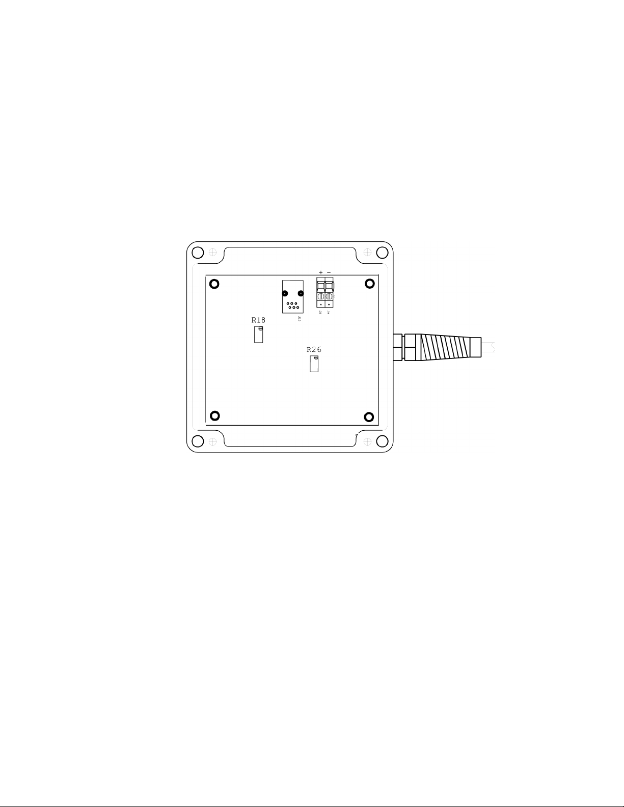
COMPLETELY DESORB) To accomplish this, refer to Figure 1.0 and locate the gain adjustment
(R26). Adjust this potentiometer so the oxygen value reflected in the analog output is equal to the
oxygen value represented by the calibration gas.
Once step 7 has been completed, resume normal operation.
Zero Adjustment
During factory calibration, the zero adjustment is made to compensate for parts per billion
concentrations of oxygen that enter the sensor housing and plumbing system through leakage. In
addition, there is a small error produced by oxygen dissolved in the electrolyte of the sensor. The
amounts vary from system to system, but it is not uncommon to have an oxygen readings in the range
of 0.1 ppm. Alpha Omega Instruments does not recommend the user make any zero adjustments
unless a new sensor has been installed. To make a zero gas adjustment, the steps outlined in the
aforementioned section should be followed with some important distinctions.
)
PPM=(mADC−4
) x
FSV/16
The sample gas used for zeroing the transmitter should be catalytically scrubbed in order to remove
residual oxygen. After treatment, the zero gas should contain < 50 ppb of oxygen. Do not attempt to
make any adjustments to the zero setting unless the quality of the zero gas sample can be assured to
be as described above.
Once the transmitter is placed on zero gas, enough time should be given for the reading to stabilize.
This length of time will be predicated on factors such as length of tubing, tubing material, flow rate, etc.
Once the zero reading has stabilized, if the oxygen value obtained from the 4-20 mADC output is not
equivalent to zero (4 mADC) an offset adjustment should be made. To do this, locate the zero
adjustment R18 (Figure 1.0). Adjust this potentiometer so the oxygen value reflected in the 4-20
mADC output is at 4 mADC. Once accomplished, the transmitter can now be placed back in service.
7

ALPHA OMEGA INSTRUMENTS CORP.
SERIES 3500 TRACE OXYGEN TRANSMITTER Instruction Manual
_____________________________________________________________________
SECTION 6.0
REPLACEMENT OF THE OXYGEN SENSOR
Procedure for Replacing the Oxygen Sensor
The Alpha Omega Instruments oxygen sensor is designed to operate for prolonged periods of time
without replacement. However, in time the sensor's performance will dictate that a replacement be
made. One indicator is a decrease in time intervals for routine calibrations. When this happens, a
replacement sensor should be ordered directly from the factory.
To install a new sensor follow the directions below:
1. Remove power from the instrument.
IT IS ADVISABLE TO KEEP A LOW PPM GAS FLOWING THROUGH THE SENSOR
HOUSING WHILE THE SENSOR IS BEING REPLACED. IT IS IMPORTANT THAT WHEN A
NEW SENSOR IS INSTALLED, THE TIME BETWEEN WHEN IT WAS UNPACKED AND
FIRST EXPOSED TO CALIBRATION GAS SHOULD BE KEPT TO AN ABSOLUTE MINIMUM.
THE AMOUNT OF TIME TAKEN TO ACHIEVE THE GAS CALIBRATION LEVEL IS A
FUNCTION OF HOW LONG THE SENSOR WAS EXPOSED TO AIR DURING
REPLACEMENT. WHEN A NEW SENSOR IS INSTALLED, IT MAY TAKE APPROXIMATELY
ONE HOUR TO REACH EQUILIBRIUM ON A CALIBRATION GAS.
2. Locate the sensor housing (metal enclosure mounted below the polycarbonate enclosure).
If the enclosure to which the sensor housing is attached is permanently mounted and the gas lines are
rigidly installed, it will be necessary to disconnect both gas inlet and outlet lines.
3. With one hand supporting the sensor housing, loosen (do not remove) the four servo clamp screws
that hold the metal ring to the enclosure. The sensor housing will drop from the enclosure.
4. Disconnect the modular connector at the top of the sensor housing.
5. Remove the socket head screws that hold the two halves of the sensor housing together. Once
these screws have been removed, the two halves should easily separate.
WHEN SEPARATING THE TOP HALF OF THE SENSOR HOUSING FROM
THE BOTTOM HALF, NEVER TWIST THE TWO AS THIS WILL CAUSE
DAMAGE TO THE SPRING LOADED PINS THAT ARE USED TO MAKE
ELECTRICAL CONNECTION TO THE SENSOR. ALSO, BE CAREFUL NOT
TO BEND THESE PINS WHEN THE SENSOR HALVES ARE APART.
6. Remove the old sensor from the bottom half of the sensor housing.
8

ALPHA OMEGA INSTRUMENTS CORP.
SERIES 3500 TRACE OXYGEN TRANSMITTER Instruction Manual
_____________________________________________________________________
THE SENSOR CONTAINS A SMALL AMOUNT OF CAUSTIC
ELECTROLYTE, WHEN DISCARDING SPENT SENSORS, CARE SHOULD
BE GIVEN NOT TO PUNCTURE THE SENSOR OR TO TAKE IT APART.
DISPOSE OF THE SPENT SENSOR ACCORDING TO LOCAL, COUNTY, OR
STATE GUIDELINES.
7. Remove the existing O ring and examine the grooves in the upper and lower halves of the sensor
housing to be sure they are clean. Replace the O ring with the new one supplied with the sensor.
Apply a light coating of silicon grease to the O ring prior to reinstalling the O ring.
8. Remove the new sensor from its package. Before installing it in the lower half of the sensor
housing, REMOVE THE CAP and then install the sensor with the two gold rings facing outward from
housing.
9. Take the two halves of the sensor housing and align them so the socket head screws can be
reinstalled. Hand tighten the socket head screws being careful to do so evenly. If any resistance is
experienced when starting any of these three socket head screws, do not force the screws into the
threads. Instead, if resistance is felt, simply rotate the screw CCW while pushing down on it until you
feel the threads snap to a new starting location and again try to install the screw in the CW direction. If
there is still a resistance to installing the screw, repeat the above procedure until the screw can be
started without any difficulty.
10. Reconnect the cable and install the sensor back on the case with the servo clamp.
11. Reconnect the gas lines and begin processing gas through the sensor housing. Apply power and
calibrate according to previous instructions.
9
ALPHA OMEGA INSTRUMENTS CORP.
Figure 1.0
Series 3500 Transmitter Board
SERIES 3500 TRACE OXYGEN TRANSMITTER Instruction Manual
_____________________________________________________________________
10

ALPHA OMEGA INSTRUMENTS CORP.
SERIES 3500 TRACE OXYGEN TRANSMITTER Instruction Manual
_____________________________________________________________________
Figure 2.0
Wiring Details for the 4-20 mADC Output
11

ALPHA OMEGA INSTRUMENTS CORP.
Figure 3.0
Series 3500 with NEMA 7 Enclosure
SERIES 3500 TRACE OXYGEN TRANSMITTER Instruction Manual
_____________________________________________________________________
12

APPENDIX A
Material Safety Data Sheet for the 3SEN Oxygen Sensor
10.1 Product Identification
Product Name
Synonyms Electrochemical Sensor, Galvanic Fuel Cell
Manufacturer Alpha Omega Instruments Corp.
Emergency Phone Number
Preparation / Revision Date
Notes
10.2 Specific Generic Ingredients
Carcinogens at levels > 0.1%
Others at levels > 1.0%
CAS Number
Oxygen Sensor Model Prefix 3SEN
40 Albion Road, Suite 100
Lincoln, RI 02865
401.333.8580
January 1, 1995
Oxygen sensors are sealed, contain
protective coverings and in normal
conditions do not present a health
hazard.
Information applies to electrolyte unless
otherwise noted.
None
Potassium Hydroxide, Lead
Potassium Hydroxide = KOH 1310-
58-3, Lead = Pb 7439-92-1
Chemical (Synonym) and
Family
Potassium Hydroxide (KOH) – Base,
Lead (Pb) – Metal
10.3 General Requirements
Use Potassium Hydroxide - electrolyte, Lead - anode
Handling Rubber or latex gloves, safety glasses
Storage
10.4 Physical Properties
Boiling Point Range
Melting Point Range
Freezing Point
Molecular Weight
Specific Gravity
Vapor Pressure
Vapor Density
pH
Solubility in H2O
Indefinitely
100 to 115° C
KOH -10 to 0° C, Lead 327° C
-40 to 0° C
KOH = 56, Lead = 207
1.09 @ 20° C
Not applicable
Not applicable
> 14
Complete
13

APPENDIX A
Material Safety Data Sheet for the 3SEN Oxygen Sensor
% Volatiles by Volume
Evaporation Rate
Appearance and Odor
10.5 Fire and Explosion Data
Flash and Fire Points
Flammable Limits
Extinguishing Method
Special Fire Fighting Procedures
Unusual Fire and Explosion Hazards
10.6 Reactivity Data
Stability
Conditions Contributing to Instability
Incompatibility
Hazardous Decomposition Products
Conditions to Avoid
None
Similar to water
Colorless, odorless aqueous solution
Not applicable
Not flammable
Not applicable
Not applicable
Not applicable
Stable
None
Avoid contact with strong acids
None
None
10.7 Spill or Leak
Steps if material is released
Waste Disposal Method
Sensor is packaged in a sealed plastic bag,
check the sensor inside for electrolyte
leakage.
If the sensor leaks inside the plastic bag or
inside an analyzer sensor housing do not
remove it without rubber or latex gloves and
safety glasses and a source of water.
Flush or wipe all surfaces repeatedly with water or
wet paper towel (fresh each time).
In accordance with federal, state and
local regulations
10.8 Health Hazard Information
Primary Route(s) of Entry
Exposure Limits
Ingestion, eye and skin contact
Potassium Hydroxide - ACGIH TLV 2
mg/cubic meter; Lead - OSHA PEL .05
mg/cubic meter
Ingestion Electrolyte could be harmful or fatal if swallowed.
Oral LD50 (RAT) = 2433 mg/kg
Eye Electrolyte is corrosive and eye contact could result
in permanent loss of vision.
Skin Electrolyte is corrosive and skin contact could result
in a chemical burn.
Inhalation Liquid inhalation is unlikely.
14

APPENDIX A
Material Safety Data Sheet for the 3SEN Oxygen Sensor
Symptoms
Medical Conditions
Aggravated
Carcinogenic Reference
Data
Other
Eye contact - burning sensation.
Skin contact - soapy slick feeling.
None
NTP Annual Report on Carcinogens - not listed
LARC Monographs - not listed
OSHA - not listed
Lead is listed by some states as a chemical
known to cause birth defects or other
reproductive harm.
15
 Loading...