


SERIES 2000
PERCENT OXYGEN ANALYZER
Product shown with optional flow meter
Alpha Omega Instruments Corp.
40 Albion Road, Suite 100
Lincoln, RI 02865
Phone: 401-333-8580
Fax: 401-333-5550
Website: www.aoi-corp.com
Email: salescontact@aoi-corp.com
Rev 3.0619.18, June 2018
COPYRIGHT ALPHA OMEGA INSTRUMENTS CORP.
ALL RIGHTS RESERVED INCLUDING THE RIGHT TO
REPRODUCE THIS MANUAL, OR ANY PORTION
THEREOF, IN ANY FORM.

ALPHA OMEGA INSTRUMENTS CORP.
SERIES 2000 PERCENT OXYGEN ANALYZER Instruction Manual
WARRANTY
Alpha Omega Instruments Corp. warrants the products delivered to be free from defects in material
and workmanship at the time of delivery to the Fob. point specified in the purchase order, its liability
under this warranty being limited to repairing or replacing, at Alpha Omega Instruments' option, items
which are returned to it prepaid within two years from the date of shipment and found to Seller’s
satisfaction to have been so defective.
Alpha Omega Instrument's two year sensor warranty offers protection for two (2) years from the date
of shipment of the Series 2000 Percent Oxygen Analyzer. Any sensor from a Series 2000 Percent
Oxygen Analyzer that fails under normal use must be returned to Seller prepaid and, if such sensor is
determined by Seller to be defective, Seller shall provide Buyer a replacement sensor. Buyer must
provide the serial number of the analyzer from which the sensor has been removed. If a sensor is
found to be defective and a new one issued, the warranty of the replacement sensor (s) is for a period
of two (2) years from the date of shipment. In no event shall Alpha Omega Instruments Corp. be liable
for consequential damages.
NO PRODUCT IS WARRANTED AS BEING FIT FOR A PARTICULAR
PURPOSE AND THERE IS NO WARRANTY OF MERCHANTABILITY.
This warranty applies only if:
(i) the items are used solely under the operating conditions and manner
recommended in this manual, specifications, or other literature;
(ii) the items have not been misused or abused in any manner or repairs
attempted thereon;
(iii) written notice of the failure within the warranty period is forwarded to
Alpha Omega Instruments Corp. and the directions received for properly
identifying items returned under warranty are followed;
(iv) the return notice authorizes Alpha Omega Instruments Corp. to examine
and disassemble returned products to the extent the Company deems
necessary to ascertain the cause of failure.
The warranties stated herein are exclusive. THERE ARE NO OTHER WARRANTIES, EITHER
EXPRESSED OR IMPLIED, BEYOND THOSE SET FORTH HEREIN, and Alpha Omega Instruments
Corp. does not assume any other obligation or liability in connection with the sale or use of said
products.
Disclaimer of Warranty
Alpha Omega Instruments makes no representation or warranties, either expressed or implied, by or with respect to
anything in this manual, including, but not limited to, implied warranties of merchantability or fitness for a particular
purpose. In no event will Alpha Omega Instruments Corp. be liable for any damages, whether direct or indirect,
special, consequential, or incidental arising from the use of this manual. Some states in the USA do not allow the
exclusion of incidental or consequential damages. Alpha Omega Instruments Corp. also reserves the right to make
any changes to improve the performance of its products at any time and without notice.
i

ALPHA OMEGA INSTRUMENTS CORP.
DO NOT TOUCH!
THIS SYMBOL IS INTENDED TO ALERT THE USER TO THE
PRESENCE OF IMPORTANT OPERATING AND MAINTENANCE
INSTRUCTIONS.
WHEN POWERED, THE PRESENCE OF UN-INSULATED
DANGEROUS VOLTAGES WITHIN THE INSTRUMENT MAY BE
OF SUFFICIENT MAGNITUDE TO CONSTITUTE A RISK OF
ELECTRICAL SHOCK RESULTING IN INJURY OR DEATH.
LEAVE ALL SERVICING TO QUALIFIED PERSONNEL.
REMOVE ALL POWER SOURCES WHEN INSTALLING OR
REMOVING AC POWER OR DATA SIGNAL CONNECTIONS
AND WHEN INSTALLING OR REMOVING THE SENSOR, OR
ELECTRONICS.
SERIES 2000 PERCENT OXYGEN ANALYZER Instruction Manual
WARNINGS
Explanation of graphic symbols
To avoid the risk of fire or electric shock, do not expose the Series 2000 Percent Oxygen Analyzer to
rain or water spray unless the enclosure is rated according to the National Electrical Manufacturer's
Association NEMA 4 (IP66)1 rating.
RF Disclaimer
This instrument generates and uses small amounts of radio frequency energy, and there is no
guarantee that interference will not occur in a particular installation. If this equipment does cause
interference to radio or television reception, try to correct the interference by one of more of the
following steps:
1. Reorient the receiving antenna.
2. Relocate the instrument with respect to the receiver.
3. Change the AC outlet of the instrument so the instrument and receiver are on different branch
circuits.
1 NEMA stands for the National Electrical Manufacturers Association and the designation IP"XX" signifies European IEC specifications 144 & 529.
ii

ALPHA OMEGA INSTRUMENTS CORP.
SERIES 2000 PERCENT OXYGEN ANALYZER Instruction Manual
TABLE OF CONTENTS
PAGE
WARRANTY i
WARNINGS ii
SECTION 1.0 INTRODUCTION 1
General Description 1
Measurement Ranges 1
Mechanical Configuration 1
Optional Equipment 2
Optional Battery Operation 2
RS-232C Option 2
RS-485 Option 3
Sample Filter Option 3
Filter Element Accessory 3
Flowmeter Option 3
Pressure Regulator Option 3
Sample Pump Option 3
Sensor Heater Option 3
General Specifications 4
SECTION 2.0 INSTALLATION PROCEDURES 6
Unpacking the Instrument 6
Electrical Installation 6
Wiring the AC/DC Power 6
Main Printed Circuit Board (Figure 1) 7
Oxygen Sensor 8
Wiring Alarm Relays 8
Wiring 4-20 mADC and 0-2 VDC Outputs 9
Wiring to the Optional RS-232C or RS-485 Outputs 10
iii

ALPHA OMEGA INSTRUMENTS CORP.
SERIES 2000 PERCENT OXYGEN ANALYZER Instruction Manual
SECTION 3.0 SYSTEM DESCRIPTION 11
Extended Life Galvanic Sensor 11
Alarms 12
On Board Switch Settings 12
Fail-Safe Operation 13
Alarm Settings 13
SECTION 4.0 DETERMINING SYSTEM CONFIGURATION 14
Model Designation 14
SECTION 5.0 OPERATION 17
Preparation for Operation 17
AC Input Voltage Selection 17
Initial Setup 18
Mounting Configurations 18
Remote Mounted Sensor Enclosures 18
Operating Procedures 19
Power On 19
Front Panel Controls and Indicators 19
Setting the Alarms 20
Alarm Processing 20
Auto-Clear Operation 20
Manual Clear Operation 21
Timing Out 21
Over Range 21
TTL Signals for Analyzers with Autoranging 21
Manual Range Changing 21
Gas System Pressure Limits 22
Sample Connections 22
iv

ALPHA OMEGA INSTRUMENTS CORP.
SERIES 2000 PERCENT OXYGEN ANALYZER Instruction Manual
SECTION 6.0 CALIBRATION PROCEDURES 23
Initial & Routine Calibration Checks 23
Calibration Gas 23
Procedure for Checking Calibration 23
Zero Adjustment 24
SECTION 7.0 REPLACEMENT OF THE OXYGEN SENSOR 25
Procedure for Replacing the Oxygen Sensor 25
SECTION 8.0 Optional Serial Communications RS232C & RS485 26
SECTION 9.0 Optional RS485 Enhanced Remote Control Commands 31
APPENDICES
Appendix A Bench Top/Portable Design/ Configuration 37
Part Number "BTP"
Appendix B Panel Mount Configurations 38
Part Numbers PNL, PNR, & PTX
Appendix C Remote Sensor Configuration, 42
Part Numbers "BTR & PNR"
Appendix D Explosion Proof Electronics/Sensor 43
Part Number "EXX".
Appendix E Explosion Proof Sensor Configuration 46
Part Number “BTX & PTX”
Appendix F Explosion Proof Sensor Housing Used with 47
BTX & PTX Configurations.
Appendix G Block Diagram for Remote 2000 PTX (Explosion Proof) 48
Appendix H MSDS for the 2SEN Oxygen Sensor 49
ADDENDA
Addendum 1 Optional Horn/Strobe Alarm 53
Addendum 2 Optional Internal Datalogger 56
Addendum 3 Optional High Volume Pump 58
v

ALPHA OMEGA INSTRUMENTS CORP.
SERIES 2000 PERCENT OXYGEN ANALYZER Instruction Manual
SECTION 1.0
INTRODUCTION
1.1 General Description
The Series 2000 Percent Oxygen Analyzer is a microprocessor controlled instrument that can be
configured with either one or three percent oxygen ranges. The instrument is powered from either
115/230 VAC, 50-60Hz, or 18-32 VDC input. Battery operation is an option for the bench top/portable
version only. Oxygen values are displayed on a 10.2 mm (0.4") high 4-1/2 digit liquid crystal display
(LCD). The oxygen sensor is mounted in a PVC housing that contains 1/4" gas inlet and outlet
compression fittings. For the bench top/ portable instrument, the sensor housing is located on the rear
panel of the electronics enclosure. For instruments equipped with a remote sensor enclosure, the
sensor housing is either mounted on the enclosure, as is the case with the watertight NEMA 4X (IP 66)
and general purpose NEMA 1 enclosures, or inside the enclosure for the explosion proof, NEMA 7
types.
The front panel of the Series 2000 Percent Oxygen Analyzer contains five switches that provide
access to the analyzer's settings. The instrument is equipped with three oxygen alarm relays and one
status alarm relay. All four relays are Form C (SPDT) types rated at 10 amps at 115/230 VAC and 30
VDC. The relays are user configurable for fail-safe operation. In addition to the four alarm contacts,
the Series 2000 Percent Oxygen Analyzer has a built-in audible alarm and three red LED's for visual
indication of an oxygen alarm condition. The audible alarm may be manually canceled at anytime. If
the audible alarm is canceled, and the alarm event continues, indications of this condition will still be
available through the front panel LED's and relay contact(s).
The Series 2000 Percent Oxygen Analyzer comes equipped with two standard analog outputs, 4-20
mADC and 0-2 VDC. For enhanced communications, the Series 2000 Percent Oxygen Analyzer can
also be equipped with optional RS-232C or RS-485 serial communications. Another standard feature
of the Series 2000 Percent Oxygen Analyzer is autoranging (three range analyzers only). This feature
provides the analyzer with the capability to move either up or down the ranges of measurement
automatically.
1.2 Measurement Ranges with Range Code Designations (codes contained in model number).
Range Code Single Ranges Range Code Multiple Ranges
A 0-100% F 0-10/25/100%
B 0-25% G 0-5/10/25%
C 0-10% H 0-1/10/25%
D 0-5%
1.3 Mechanical Configurations with Part Number Designations.
Mechanical Code Description
BTP The analyzer enclosure is suitable for bench top or portable use and comes
equipped with a carrying handle. The sensor housing is mounted on the rear of
the enclosure (refer to Appendix A). The enclosure is fabricated from
polycarbonate.
PNL Similar to the BTP configuration with the addition of an aluminum panel frame.
It is not equipped with a carrying handle (refer to Appendix A). The enclosure is
made from polycarbonate with a watertight, NEMA 4X (IP66) rating.
Page 1

ALPHA OMEGA INSTRUMENTS CORP.
SERIES 2000 PERCENT OXYGEN ANALYZER Instruction Manual
BTR This configuration is comprised of two enclosures (electronics and sensor). The
electronics enclosure is suitable for bench top installations and is made from
polycarbonate with a watertight, NEMA 4X (IP66) rating. The sensor housing is
also made from polycarbonate and carries a NEMA 4X (IP66) rating (refer to
Appendix C). Three feet (1 meter) of interconnecting cable is standard with
additional cabling (up to 4,000 feet) (1,220 meters) available at the time of
order.
PNR Similar to the BTR configuration with the exception of the
electronics enclosure that is equipped with a steel panel frame.
BTX This configuration is comprised of two enclosures (electronics and sensor). The
electronics enclosure is suitable for bench top installations and is made from
polycarbonate with a watertight, NEMA 4X (IP66) rating. The oxygen sensor
housing is mounted inside an aluminum, explosion proof enclosure rated
NEMA 7 for use in areas requiring Class 1, Groups B,C,D, Division 1; Class II,
Groups E,F,G; and Class III protection (refer to Appendix D). Three feet (1
meter) of interconnecting cable is standard with additional cabling (up to 4,000
feet) (1,220 meters) available at the time of order.
PTX Similar to the BTX configuration with the exception of the electronics enclosure
that is equipped with a steel panel frame.
EXX In this configuration both the electronics and sensor are mounted within an
aluminum explosion proof enclosure rated NEMA 7 for use in areas requiring
Class 1, Groups B,C,D, Division 1; Class II, Groups E,F,G; and Class III
protection (refer to Appendix B).
1.4 Optional Equipment
The Series 2000 Percent Oxygen Analyzer Monitor incorporates standard features that make it
suitable for many applications. However, for certain requirements, the user may desire to augment
the capabilities of the instrument by equipping it with one or more options.
1.4.1 Battery Operation Part Number (P/N 2BAT)
The Series 2000 can be equipped so that it may be powered from a normal AC/DC source as well as
an optional built-in NiMH (nickel metal hydride) battery pack. The batteries are installed at the factory
and are designed for applications where the user desires to power the analyzer for short periods using
the batteries. With the battery option, the Series 2000 will operate for a period of at least 8 hours. If
equipped with a sample pump, operating time will be reduced to less than four hours of continuous
use. Other items such as alarms, use of the 4-20 mADC output, etc. could reduce the time intervals
between battery recharging. The Series 2000 is equipped with a “smart charging” capability for the
Nickel Metal Hydride (NiMH) battery pack. Smart charging eliminates the risk of the battery pack
being over-charged (not available with explosion proof systems). To achieve a full-charge after the
batteries have been discharged, allow for approximately 16 hours of charging time.
1.4.2 RS-232C Option (P/N 2RS2)
The RS-232C option is installed at the factory and is designed for applications where enhanced serial
communications is required between the Series 2000 Percent Oxygen Analyzer and a host system.
The maximum distance between monitor and host is 50 feet (15.2 meters).
1.4.3 RS-485 Option (P/N 2RS4)
Page 2

ALPHA OMEGA INSTRUMENTS CORP.
SERIES 2000 PERCENT OXYGEN ANALYZER Instruction Manual
The RS-485 option is installed at the factory and is designed for applications where enhanced serial
communications is required between one or several analyzers and a host system over the same
communications channel. The RS-485 format allows both sending and receiving of signals over
greater distances than RS-232C, making it ideal for installations where the analyzer(s) are located at
distances greater than 50 feet (15.2 meters) from the host. The maximum distance recommended
between devices is 4,000 feet (1,220 meters).
1.4.4 Sample Filter Option (P/N 295S)
Miniature T-type 316 stainless steel filter with 1/8" NPT in-line ports. Recommended when particle
loading exceeds 3 mg/ft3 and hydrocarbon mist exceeds 0.7 mg/ft3. Installed at the factory unless
otherwise specified by the customer. Other types of filters are available from Alpha Omega
Instruments. Please consult the factory for specific recommendations.
1.4.5 Filter Element Accessory (P/N 2FBX)
Filter element for the 395S
1.4.6 Flowmeter Option (P/N 2FLM)
Durable one piece clear acrylic flowmeter with easy to read scale in liters per minute.
1.4.7 Pressure Regulator Option (P/N 2PRR)
Stainless steel pressure regulator with a 3,000 psig (211 kg/cm2) inlet capacity and an adjustable
outlet pressure range of 0-5 psig (0 to 0.35 kg/cm2). The regulator does not include a gauge.
1.4.8 Sample Pump Option (P/N 2PMP)
Sample pump designed for applications where the sample pressure is insufficient to transport the
sample through the sensor housing.
1.4.9 Sensor Heater Option (P/N 2HTR)
Sensor heater used for applications where low ambient temperatures are encountered, or where
constant temperature conditions within the enclosure are desired. This option will not operate off
battery power and is only available with the EXX configuration.
Page 3

ALPHA OMEGA INSTRUMENTS CORP.
SERIES 2000 PERCENT OXYGEN ANALYZER Instruction Manual
1.4 General Specifications
Measurement Ranges (Percent Oxygen)
Single Range Multiple Range
0-100 0-10/25/100
0-25 0-5/10/25
0-10 0-1/10/25
0-5
Accuracy¹: ±1% of full scale (± 5% for ranges of 0-1%)
Linearity: ±1%
Response Time: 90% of full scale response in less than 20 seconds (typical)
Sensor Type: Ambient Temperature Electrochemical Sensor with EES
Temperature Compensation: Standard
Pressure Compensation: Standard
Operating Temperature: 40° to 104° F (5° to 40°C)
<40°F (<5°C) use heated sensor enclosure
>104°F (>40°C) cooling of sensor required
Warranty: 3 years electronics/ 2 years sensor
ELECTRICAL
Display: 0.4" (10.2 mm) high, 4-1/2digit LCD
Resolution: 0.1 %
Input Power: 115/230 VAC, 50-60Hz or 18-32 VDC, battery backup available
as an option for some models
Outputs: 4-20 mADC and 0-2 VDC standard as is a TTL output for range
identification. RS-232C or RS-485 serial communication optional.
Oxygen Alarm Relays: Three (3) SPDT Form C contacts rated 10A @ 30 VDC/115/230
VAC. User selectable for fail-safe or non fail-safe.
Instrument Status Alarm: Rated identically to the O2 relays
Audible Alarm: Internal buzzer with audible cancel
Page 4

ALPHA OMEGA INSTRUMENTS CORP.
SERIES 2000 PERCENT OXYGEN ANALYZER Instruction Manual
SAMPLE GAS CHARACTERISTICS
Flow Rate: 1.0 to 2.0 SCFH (0.5 to 1.0 liter/min)
Sample Gas Temperature: 32° to 104° F (0° to 40°C)
Sample Gas Pressure Limits: 0.1 to 1.5 psig (0.007 to 0.1 kg/cm2).
Entrained Solids: <3 mg/ft³: no in-line filter required
>3 mg/ft³: in-line filter is required
Hydrocarbon Mist: <0.7 mg/ft³: no in-line filter required
>0.7 mg/ft³: in-line filter is required
CONSTRUCTION²
Electronics Control Unit: Polycarbonate with a hinged clear front cover, rated NEMA 4X
(IP 66)
Control Unit Dimensions: 9.45 in. (240.5 mm) length
6.50 in. (165.1 mm) width
6.20 in. (157.5 mm) depth
Note: All dimensions are without optional equipment
Gas Connections: Quick connect for 1/4” OD flex tubing or optional 1/4” stainless
steel compression fittings
Sensor Mounting: Local or optional remote mounting
Weight: 11lbs (4.98 kg) (Bench-top Configuration.)
¹ Stated at constant temperature and constant pressure.
² Other mechanical configurations available-consult factory.
Alpha Omega Instruments Corp. reserves the right to change or modify its product specifications without notice.
Page 5

ALPHA OMEGA INSTRUMENTS CORP.
NOTE: IF DAMAGE HAS BEEN FOUND, DO NOT PROCEED
FURTHER, BUT INSTEAD, CONTACT THE FACTORY.
ELECTRICAL INSTALLATION SHOULD BE PERFORMED BY A
CERTIFIED ELECTRICIAN AND SHOULD COMPLY WITH APPLICABLE FEDERAL, STATE, OR LOCAL ELECTRICAL SAFETY
CODES.
SERIES 2000 PERCENT OXYGEN ANALYZER Instruction Manual
SECTION 2.0
Installation procedures
2.1 Unpacking the Instrument
Upon opening the shipping container, carefully unpack the instrument to check if the outer surfaces
have been damaged. If so, report the findings immediately to Alpha Omega Instruments who will, in
turn, provide further instructions.
If there is no apparent damage, check the contents to ensure all items were shipped. In some cases,
items may be back-ordered. All damage and shortage claims must be made known to Alpha
Omega Instruments within 10 days after receipt of shipment.
There are six screws on the Series 2000 Percent Oxygen Analyzer that fasten the clear cover to the
polycarbonate enclosure. Loosen these screws to disengage them from the enclosure, and open the
cover exposing the front panel membrane switches. For the explosion proof version, their are 18
fastening bolts that need to be removed in order to remove the cover from the base. The membrane
panel is installed on a metal backing plate that is hinged and swings out in the same direction as the
cover. Swing out the membrane panel and check inside the control unit to make sure no components
have been loosened or dislodged. If there are loose or dislodged components, notify the factory for
further instructions. If all is found to be satisfactory, the installation procedure can begin.
2.2 Electrical Installation
The Series 2000 Percent Oxygen Analyzer is shipped with a power cord (except for the explosion
proof versions). Some installations may require wiring through conduit into the electrical hub on the
rear panel (where the existing power cord is installed). For such installations, removal of the existing
power cord can be easily accomplished as described in section 2.2.1. The position of jumper S2,
which is located at the lower left quadrant of the printed circuit board determines the line voltage
setting. The default setting is 115 VAC, 50-60Hz. If the AC input voltage is changed in the field,
please refer to Section 5.1.1 for instructions.
2.2.1 Wiring the AC/DC Power in Place of the Existing Power Cord
Referring to the printed circuit board diagram (FIGURE 1.0) on the next page, locate the AC power
terminals 31,32, and 33. Each connector is equipped with a screw terminal wire holder to facilitate
insertion or removal of the wire from the connector. Strip away approximately 6.0 mm (1/4 inch) of
insulation from each of the three conductors and then connect AC line, AC neutral, and chassis
ground to each connector. Tighten down on each screw turning clockwise to securely fasten each
conductor. If the primary power to the instrument is direct current (DC), wire to terminals 29 (BAT+)
and 30 (BAT-). Please refer to the cautionary note on page 17 regarding optional battery operation.
Page 6

ALPHA OMEGA INSTRUMENTS CORP.
SERIES 2000 PERCENT OXYGEN ANALYZER Instruction Manual
FIGURE 1.0
Page 7

ALPHA OMEGA INSTRUMENTS CORP.
SERIES 2000 PERCENT OXYGEN ANALYZER Instruction Manual
2.2.2 Oxygen Sensor
Wiring of the oxygen sensor has been done at the factory. For information regarding sensor
replacement, please refer to Section 7.0.
2.2.3 Wiring Alarm Relays
In addition to the cable used for the AC/DC power to the Control Unit, access to the control signals
generated from the Series 2000 Percent Oxygen Analyzer is accomplished using signal cabling. This
cable is installed through the output cable gland on the rear of the electronics enclosure. The number
of conductors needed is determined by the number of functions to be controlled.
The Series 2000 Percent Oxygen Analyzer is equipped with four single pole double throw (SPDT)
relays with Form C contacts rated at 10 amperes @ 30 VDC and 115/230 VAC. All alarm relays are
user configurable with the three oxygen alarms defaulting to factory setting of low oxygen alarms. To
configure any of the three oxygen alarm relays to act as high alarms, please refer to Section 5.2.3. As
a reminder, Alarm 4 which is not displayed as a discrete alarm on the front panel, is the instrument
status alarm.
The technique for wiring to the connectors is identical to that discussed in Section 2.2.1. The wiring
configuration is as follows:
Terminal Alarm 1 Relay
26 Common Contact
27 Normally Open Contact
28 Normally Closed Contact
Alarm 2 Relay
23 Common Contact
24 Normally Open Contact
25 Normally Closed Contact
Alarm 3 Relay
20 Common Contact
21 Normally Open Contact
22 Normally Closed Contact
Instrument Status Alarm
17 Common Contact
18 Normally Open Contact
19 Normally Closed Contact
TABLE 1.0 on the next page illustrates the various wiring configurations for the four alarms in the
Series 2000 Percent Oxygen Analyzer based on whether the alarms are going to be configured for
fail-safe or non fail-safe operation.
Page 8

ALPHA OMEGA INSTRUMENTS CORP.
SERIES 2000 PERCENT OXYGEN ANALYZER Instruction Manual
Alarm ONContacts
shorted for
Fail-safe OFFFail-safe ON
each Alarm
Relay
High or Low O2
Alarm1 /
Relay 1
High or Low O2
Alarm2 /
Relay 2
High or Low O2
Alarm3 /
Relay 3
Low Battery or
Instrument
Status/ Relay 4
Each of the aforementioned alarm relays can be individually configured for fail-safe operation by
means of a DIP switch located on the main printed circuit board (refer to Section 3.3). If the
instrument is equipped with optional RS-232C or RS-485 communications, the alarms can also be
controlled via these outputs. See the caution note below.
28(NC) to
26(COM)
25(NC) to
23(COM)
22(NC) to
20(COM)
19(NC) to
17(COM)
TABLE 1.0
27(NO) to
26(COM)
24(NO) to
23(COM)
21(NO) to
20(COM)
18(NO) to
17(COM)
IF THE SERIES 2000 PERCENT OXYGEN ANALYZER IS EQUIPPED
WITH EITHER RS-232C OR RS-485 COMMUNICATIONS, PLEASE
REFER TO SECTION 8.0.
2.2.4 Wiring 4-20 mADC and 0-2 VDC Outputs
The Series 2000 Percent Oxygen Analyzer has two standard linear outputs, 4-20 mADC and 0-2 VDC
over the instrument's range(s). These outputs can be measured simultaneously. To wire to the 4-20
mADC output, wire to terminals 12 (4-20) and 13 (AGND). To wire to the 0-2 VDC output, use
terminals 8 (positive {labeled DAC}) and 9 (negative {labeled AGND} ). The terminals can be found on
the right side of the printed circuit board (refer to FIGURE 1.0). Note: If a jumper wire is in place
between terminals 12 and 13, it must be removed prior to using the 4-20 mADC output.
NOTE: IF THE 4-20MA DC OUTPUT IS NOT GOING TO
BE USED, IT SHOULD BE SHORTED TO AVOID AN
OPEN LOOP WARNING VIA TERMINAL 10 (B-LO)
Page 9

ALPHA OMEGA INSTRUMENTS CORP.
SERIES 2000 PERCENT OXYGEN ANALYZER Instruction Manual
2.2.5 Wiring to the Optional RS-232C or RS-485 Outputs.
The RS-232C and RS-485 digital communications are options with the Series 2000 Percent Oxygen
Analyzer. Unlike the analog outputs, the Series 2000 Percent Oxygen Analyzer can be ordered with
either option, but not both. To wire for either the RS-232C or RS-485, use terminals 14 (TXD) for
transmit and 15 (RXD) for receive. Note: You must connect the GND terminal for RS-232C and
RS-485 for the instrument to work properly. Further details on these communication channels
are contained in Section 8.0. Section 8.0 is included as part of this manual even if the Series
2000 Percent Oxygen Analyzer has not been equipped with either of the two aforementioned
digital communication loops.
Page 10

ALPHA OMEGA INSTRUMENTS CORP.
SERIES 2000 PERCENT OXYGEN ANALYZER Instruction Manual
SECTION 3
SYSTEM DESCRIPTION
3.1 Extended Life Galvanic Sensor
The Series 2000 Percent Oxygen Analyzer features an extended life oxygen sensor with a weak acid
electrolyte system. The weak acid electrolyte system retards passivation of the sensor anode by
allowing the products of oxidation to dissolve in the acid electrolyte. In effect, the sensor is renewed
continuously as the weak acid electrolyte tolerates over 20 times the lead oxide (PbO) than potassium
hydroxide (KOH) based sensors. The result is a sensor with a greatly extended useful life.
The extended life sensor is a lead-oxygen battery comprised of a lead anode, and gold cathode, and a
weak acid electrolyte. A gold electrode is bonded onto a non-porous Teflon (FEP) membrane. A small
amount of oxygen permeating through the membrane is reduced electrochemically at the gold
electrode. A resistor and a thermistor (for temperature compensation) are connected between the
cathode and anode. As a result, the lead-oxygen battery is always discharged.
Current flowing through the resistor and thermistor is proportional to the oxygen concentration of the
gas in contact with the Teflon membrane. By measuring the voltage between the resistor and the
thermistor, oxygen concentration can be accurately determined. The two electrode reactions are
depicted below:
Cathode: O2 + 4H+ + 4e 2H2O
Anode: 2Pb + 2H2O 2PbO + 4H+ + 4e
Overall: O2 + 2Pb 2PbO
If PbO generated at the anode remains on the anode, the anode's potential will change and the output
voltage of the sensor would become extremely low. However, in actuality the surface of the lead
anode is continuously renewed because PbO is dissolved back into the electrolyte.
There is a maximum level to the solubility of PbO in the weak acid electrolyte. As a result, when the
electrolyte becomes saturated with PbO, the sensitivity of the sensor will begin to drop signaling time
for replacement of the sensor. When the extended life oxygen sensor is used in ambient air monitoring
applications, carbon dioxide (CO2) that is present will not adversely affect the sensor's performance.
Due to the weak acid electrolyte, CO2 will not react with the electrolyte to form potassium carbonate as
it does with KOH based sensors. As a result, there is no loss in output due to the presence of CO2.
Page 11

ALPHA OMEGA INSTRUMENTS CORP.
SERIES 2000 PERCENT OXYGEN ANALYZER Instruction Manual
3.2 Alarms
One of the primary functions of the instrument is to alert the user when alarm conditions have
occurred. To this end, four alarm relays, each capable of switching up to 10 Amperes, are provided.
These isolated relays are single pole double throw (SPDT) relays for maximum user flexibility. These
relay outputs, along with the simultaneous LED and annunciator operation, serve to give maximum
notification to the user of an alarm condition.
An "open collector" output, more appropriately called an "open drain output", in this case, provides an
additional level of operator output for signaling alarm purposes. This "open drain output", from a 50
volt MOSFET transistor, is normally open, but will close or short to ground to indicate an alarm
condition if the 4 to 20 milliamp loop is open.
The front panel display and Relay #4 will indicate a low battery if the instrument is equipped with the
Battery Backup option.
3.3 On Board Switch Settings
Setting the alarms for fail-safe operation and automatic alarm clearing can be accomplished by using
an on board switch bank (SW6) located in the upper right quadrant of the printed circuit board (refer to
FIGURE 1.0). This switch bank has eight (8) individual switches for configuring the Series 2000
Percent Oxygen Analyzer. Refer to FIGURE 3.0 on the next page for a description of the switches.
The Series 2000 Percent Oxygen Analyzer is shipped from the factory with switch #8 in the "OFF"
("switch settings" mode) position. This is the default configuration and will force the Series 2000
Percent Oxygen Analyzer to read the other switches in order to configure the alarms when power is
applied or a warm boot has occurred. If switch #8 is in the "ON" ("user configuration" mode) position,
the Series 2000 Percent Oxygen Analyzer will be configured using battery backed configuration
information. This means the analyzer will ignore the switch settings altogether and "boot" up to user
configured memory. The user configured memory is that which is set up via the front panel or external
communications loop (refer to Section 5.2.2).
Page 12

ALPHA OMEGA INSTRUMENTS CORP.
SW6
O
N
1 2 3 4 5 6 7 8
RELAY 1 - NORMAL
RELAY 2 - NORMAL
RELAY 3 - NORMAL
RELAY 4 - NORMAL
OXYGEN ALARM 3 (LO)
MANUALLY CLEAR ALARMS
SWITCH SETTINGS
RESERVED
RELAY 1 - FAIL-SAFE
RELAY 2 - FAIL-SAFE
RELAY 3 - FAIL-SAFE
RELAY 4 - FAIL-SAFE
OXYGEN ALARM 3 (HI)
AUTO CLEAR ALARMS
USER CONFIGURATION
RESERVED
SW6
SERIES 2000 PERCENT OXYGEN ANALYZER Instruction Manual
3.3.1 Fail-Safe Operation
The Series 2000 Percent Oxygen Analyzer will "boot" up based on the settings of oxygen alarm
switches #1 through #4. Switches #1 through #4 control the fail-safe operation for each of the four
alarm relays. Each switch must be turned "ON" to be fail-safe (refer to FIGURE 3.0). In the fail-safe
mode, upon an alarm condition, the corresponding relay will change state (from energized to deenergized) upon loss of AC power. The factory settings for switches #1 through #4 is "OFF" (normal
operation or non fail-safe).
3.3.2 Alarm Settings
With switch #8 in the "OFF" position, the Series 2000 Percent Oxygen Analyzer defaults to configuring
all three Oxygen Alarms as low alarms. With switch #8 in the "ON" position, all user settings will be
retained. Note: to read the switches while operating, just perform a "warm boot". (See Section 5.2.1)
FIGURE 3.0
IF ANY ALARM IS NOT GOING TO BE USED, IT SHOULD
BE DISABLED. TO DO SO, FIRST CONFIGURE EACH
ALARM AS A LOW ALARM, AND THEN SET THE ALARM
TO 0.00
Page 13

ALPHA OMEGA INSTRUMENTS CORP.
P/N KEY:
A
Code Base Model
2000
Series 2000 Percent Oxygen Analyzer with three alarm relays, instrument
status alarm relay, digital display, audible alarm, visual alarm indicators,
NEMA 1 enclosure, 4-20 mADC, and 0-2 VDC analog outputs.
B
Oxygen Ranges
Range Code Range
A 0-100%
B 0-25%
C 0-10%
D 0-5%
E
Left Blank
F 0-10/25/100%
G 0-5/10/25%
H 0-1/10/25%
C
Code Input Power
115 115 VAC
50-60 Hz
230 230 VAC
50 Hz
Input Power Configurations
A
B C
D
Base Model
Code
Range
Code
Input
Code
Mechanical
Configuration Code
SERIES 2000 PERCENT OXYGEN ANALYZER Instruction Manual
SECTION 4.0
DETERMINING SYSTEM CONFIGURATION
4.1 Model Designation
Before proceeding to the following sections, it is important to determine the system configuration for
the selected analyzer. To best accomplish this, refer to the purchase order to obtain the part number
that was ordered and compare it to the range, input power configuration, and mechanical configuration
shown below.
Page 14

ALPHA OMEGA INSTRUMENTS CORP.
SERIES 2000 PERCENT OXYGEN ANALYZER Instruction Manual
Mechanical Configurations
Code Configuration
BTP Benchtop/portable electronics enclosure with carrying handle.
The sensor is mounted on the rear of the electronics enclosure.
PNL Panel mounted electronics enclosure with the sensor mounted
on the rear of the electronics enclosure.
BTR Benchtop electronics enclosure without carrying handle. The sensor
is mounted within a separate NEMA 4X (IP 66) enclosure. Three
D
feet (1 meter) of interconnecting cable is provided to connect the electronics
(1,220 meters), is available.
PNR
within a separate NEMA 4X (IP 66) enclosure. Three feet (1 meter) of
interconnecting cable is provided to connect the electronics
to the sensor. Additional cabling, up to a maximum of 4,000 feet
(1,220 meters), is available.
BTX Benchtop electronics without carrying handle. The sensor is mounted
within a separate explosion proof enclosure rated NEMA 7 for use in
areas requiring Class 1, Groups B,C,D, Division 1; Class II, Groups E,F,G;
and Class III protection. No interconnecting cabling is provided. Cable is
available up to a maximum of 4,000 feet (1,220 meters).
PTX Panel mounted electronics. The sensor is mounted within a
separate explosion proof enclosure rated NEMA 7 for use in
areas requiring Class 1, Groups B,C,D, Division 1; Class II, Groups E,F,G;
and Class III protection. No interconnecting cabling is provided.
Cable is available at up to a maximum of 4,000 feet (1,220 meters).
EXX Electronics and sensor housing are mounted within one explosion
proof enclosure rated NEMA 7 for use in areas requiring Class 1,
Groups B,C,D, Division 1; Class II, Groups E,F,G; and Class III protection.
Panel mounted electronics enclosure. The sensor is mounted
Configuration example : Series 2000 Percent O2 Analyzer with a range of 0-10/25/100%, a selected
power input of 115 VAC 50-60 Hz, with a benchtop/portable mechanical
configuration (p/n 2000-F-115-BTP)
Page 15

ALPHA OMEGA INSTRUMENTS CORP.
OPTIONS/ACCESSORIES
Item Description P/N
RS-232C Serial Communications
-Maximum distance between host and analyzer is 50 feet. (15 meters).
2RS2
RS-485 Serial Communications-
Provides capability to communicate with several analyzers
2RS4
High Capacity Sample Filter -
316 stainless steel (SS) body with 316 SS filter element. Filters
295S
particle sizes > 5 microns. The filter housing is equipped with 1/4” compression gas fittings.
Spare Filter Elements-
316 stainless steel filter elements for the 295S Filter.
2FBX
Coalescing Filter-
Filter with aluminum housing. Recommended for samples containing a very
2CF
light mist and particles > 30 microns.
Spare Filter Elements
for the 2CF.
2CFE
Flowmeter
-Durable one-piece acrylic flowmeter (without flow control adjustment).
2FLM
Flowmeter-
Durable one-piece acrylic flowmeter (with flow control adjustment).
2FLMC
Pressure Regulator-
Aluminum body with a maximum pressure input of 100 psig (7.03kg/cm2).
2LPR
Pressure Regulator-
High capacity stainless steel pressure regulator with a 3000 psig
2PRR
(211 kg/cm2) inlet capacity and an adjustable outlet pressure range of 0 to 5 psig (0 to 0.35 kg/cm2)
(does not include indicating gauge).
Sample Pump
-For applications when the sample pressure is from 12 psia (827 mbar) to
2PMP
14.9 psia (1027 mbar). Maximum sample line limit is 25 feet (7.6 meters). When mounted on the
instrument,the enclosure rating is NEMA 1, general purpose.
High Capacity Sample Pump
- For applications when the sample pressure is from 10 psia (690 mbar)
2PMPH
to 14.9 psia (1027 mbar) or, if the sample line exceeds 25 feet (7.6 meters). Should be used
with the 2FLMC flowmeter. When mounted on the instrument, the enclosure rating is general purpose.
Sensor Heater
-Available with BTX, PTX, and EXX only. Designed to keep the sensor
2HTR
from being damaged due to low temperatures.
Mounting Plate
- Painted aluminum mounting plate ( 16” x 16”) (40cm x 40cm nominally)
2MPL
used for mounting items such as the remote sensor enclosure, flowmeter, sample pump, etc.
Items mounted at factory.
Battery Operation:
Nickel Metal Hydride Battery Pack used to power instrument when AC
2BAT
power is not available. The instrument is equipped with a built-in battery charger.
Internally mounted datalogger
: Capable of storing up to 32,000 oxygen readings.
2DL
Replacement Sensor-
Replacement sensor for the Series 2000 Percent Oxygen Analyzer.
2SEN
SERIES 2000 PERCENT OXYGEN ANALYZER Instruction Manual
Page 16
ALPHA OMEGA INSTRUMENTS CORP.
SERIES 2000 PERCENT OXYGEN ANALYZER Instruction Manual
Section 5.0
OPERATION
5.1 Preparation for Operation
5.1.1 AC Input Voltage Selection
At the time of shipment, the Series 2000 Percent Oxygen Analyzer is set up to operate on the line
voltage specified in the purchase order. If the line voltage is not specified, the instrument will be
configured for operation on 115 VAC, 50-60Hz. If the instrument is going to be powered from an
external DC power source, move on to the next section.
The input voltage can be changed in the field by changing jumper (S2) located on the lower left
quadrant of the printed circuit board (refer to FIGURE 1.0) When the Series 2000 is configured for
operation on 115 VAC, it contains a 0.5 ampere slow blow fuse (fuse type is Wickman 374050004).
For 230 VAC operation, the same value fuse can be used. However, please refer to item 3 below for
the jumper change required to change AC voltage inputs.
BE SURE TO USE THE APPROPRIATE FUSE RATING IF
THE INSTRUMENT IS CHANGED TO A DIFFERENT AC LINE
VOLTAGE .
Changing the AC input can be done as follows:
1 Disconnect the Series 2000 Percent Oxygen Analyzer from all AC power.
2 Swing out the front panel to gain access to the main printed circuit board
(refer to Section 2.1 for instructions). For explosion proof instruments, removal of the cover bolts
must be done to gain access to the inside of the instrument.
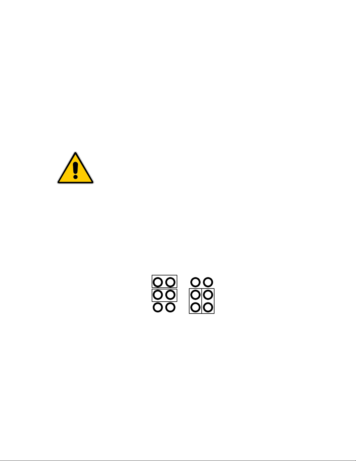
3 Examine the jumpers on the main circuit board. Shown below are the two ways of installing the AC
input selection jumpers at S2.
S2
4
S2
230 115
4. To change the AC configuration, remove the jumpers and place them according to the above
diagram.
5. Remove the fuse located on the main printed circuit board (refer to FIGURE 1.0) and replace it
with one of the proper value for the AC input voltage selected.
6. Reassemble the instrument and proceed to the next section.
Page 17
ALPHA OMEGA INSTRUMENTS CORP.
IT IS HIGHLY RECOMMENDED THAT THE CALIBRATION OF THE
ANALYZER BE CHECKED PRIOR TO INITIAL STARTUP.
NOTE FOR BATTERY OPERATION
SERIES 2000 PERCENT OXYGEN ANALYZER Instruction Manual
5.1.2 Initial Set Up
The Series 2000 Percent Oxygen Analyzer is essentially ready to use out of the shipping container.
The analyzer has been calibrated at the factory and, under normal conditions, recalibration should not
be required at initial start-up. However, due to the rigors of shipment, it is possible that settings within
the instrument could change and, as a result, it is highly recommended that the calibration be checked
prior to initial startup.
5.1.3 Mounting Configurations
Bench top/Portable (BTP Configuration) The BTP is the basic Series 2000 Percent Oxygen Analyzer
configuration that has the sensor housing mounted on the rear panel of the electronics enclosure. The
analyzer is designed for either bench top or portable applications. All gas and electrical connections
are located on the instrument's rear panel for ease of access. The power switch is located on the side
of the instrument.
Panel Mounting (PNL)- Like its BTP counterpart, the sensor housing is mounted on the rear panel of
the electronics enclosure. In the PNL configuration, a panel mounting frame is supplied. Make the
appropriate panel modifications as indicated in the drawing.
Remote Sensor Mounting- There are several remote sensor mounting configurations for Series 2000
Percent Oxygen Analyzer. Check the purchase order to determine what mechanical configuration was
specified in the order.
5.1.4 Remote Mounted Sensor Enclosures
For analyzers equipped with remote mounted sensor enclosures, the electronics control unit and
remote mounted sensor enclosures need to be connected via interconnecting cable. If the standard
length of cable is ordered with the instrument (3 feet) (1 meter), wiring to the electronics control unit
has been done at the factory (no wiring is supplied with the explosion proof systems). For all
nonstandard lengths, the cabling will be shipped without being terminated. Please refer to Figure 1.0
to locate the various terminals for connecting the sensor, alarms, outputs, pump, heater, etc.
Optional Battery Operation
If the Series 2000 has been equipped with optional NiMH batteries, it is designed to provide up to eight hours of
operation on a fully charged set of batteries (without pump). With a pump, one may expect to obtain up to 3-4 hours
of continuous operation before charging of the batteries will be necessary. The batteries should be fully charged
upon receipt of the analyzer. If not, the user should recharge the batteries upon initial startup by powering the
analyzer from AC power. NOTE: THE POWER ON SWITCH MUST BE KEPT IN THE “ON” POSITION DURING
CHARGING.
Important: Re-charge batteries 16 hours before initial startup. Batteries are disconnected for
shipment.
The battery option should never be used when the analyzer is powered from a separate DC source. This will cause the batteries to
overcharge which may cause the batteries to explode. Be certain all wiring (alarms, remote sensor, RS-232C, etc.) has been done
before applying AC power to the instrument.
Page 18

ALPHA OMEGA INSTRUMENTS CORP.
SERIES 2000 PERCENT OXYGEN ANALYZER Instruction Manual
5.2 Operating Procedures
5.2.1 Power ON
Power to the instrument is applied when the power cord is plugged into an AC outlet. The Series 2000
Percent Oxygen Analyzer has battery backed RAM so when the instrument undergoes a cold start, all
values, set by the user via the front panel or optional RS-232C and RS-485, will be maintained if
switch #8 is set to the "ON" position, otherwise referred to as the user configuration mode (See
section 3.3). The cold boot gives the user the opportunity to make sure the microprocessor, internal
memory, front panel LED's, and the audible alarm are functioning normally. During a cold start
sequence, the instrument's front panel liquid crystal display (LCD) will display a series of dashes in
series like[¯ ¯ ¯ ¯][- - - -][_ _ _ _], each of the three front panel LED's will blink simultaneously for
approximately 5 seconds, and the audible alarm will sound intermittently for as long as the LED's are
blinking. After this, the display will briefly show the onboard switch settings such as [
| | | | | | | |
example, switch #8 is ON and all the others are in the OFF positions.
To perform a warm boot and read the internal switch settings, make sure SW6 - switch # 8 is "OFF"
and push the front panel UP, DOWN, and Alarm 3 buttons simultaneously. Do not hold the buttons
down very long after the display shows the dashes described above. You will see the same sequence
as above, however, switch #8 will indicate low. Powering on with switch #8 in the "OFF" position will
cause the Series 2000 Percent Oxygen Analyzer to default to the specific switch settings.
|]. In this
5.2.2 Front Panel Controls and Indicators
The front panel of the Series 2000 Percent Oxygen Analyzer contains a 4 digit liquid crystal display
(LCD), three (3) alarm set push-button switches, three alarm LED's, and up and down push-button
switches.
Liquid Crystal Display: The primary function of the LCD is to display the concentration of oxygen in
the sample being measured in terms of percent oxygen by volume. Within approximately five seconds
after a cold start, the Series 2000 Percent Oxygen Analyzer will measure and display the oxygen
concentration of the sample gas exposed to the sensor. In addition to displaying oxygen values, the
LCD indicates certain status levels. When setting an oxygen alarm value, it is also possible to toggle
the alarm from high to low to high etc. The display will show [ HI ] or [ LO ], very briefly, upon pressing
the up and down arrows simultaneously, indicating either a high or low alarm. Note: this is a toggle
function, so if it shows the opposite setting desired, just toggle it back. Then exit the alarm set routine
by pressing an alarm button. When the Series 2000 Percent Oxygen Analyzer is equipped with the
Battery Option, the LCD will display [LOBAT ] when battery power has reached the point when
normal instrument operation is in jeopardy. To protect important information stored in the analyzer’s
memory [monitor’s memory], the analyzer [monitor] suspends operation of the microprocessor when
further operation could corrupt that memory. The microprocessor displays the word HALT on the LCD,
then suspends further operation. The microprocessor does not resume operation until power is
reapplied and the battery voltage is verified to be high enough to safely take over operation for a short
time in the event of a recurring power failure.
When calibrating the Series 2000 Percent Oxygen Analyzer, you will notice that upon initiating that mode, the
liquid crystal display momentarily reads [ CAL] and then the value of the oxygen concentration of the gas being
measured is displayed. For further information on calibrating the analyzer, please refer to Section 6.0.
Oxygen Alarms: The Series 2000 Percent Oxygen alarms are set at the factory as low alarms. Any one of
these alarms can be set by the user for operation as high alarms also. Please refer to Section 3.2 "Alarm
Settings" for instructions on how to set Alarm 3 for either high or low operation. Note: All alarms are user
configurable via SW-6, - switch #8 (refer to section 3.3).
Page 19

ALPHA OMEGA INSTRUMENTS CORP.
SERIES 2000 PERCENT OXYGEN ANALYZER Instruction Manual
5.2.3 Setting the Alarms
Assuming that no alarms are currently activated (no led's are lit), press the desired alarm switch on
the front panel, "Alarm 1", "Alarm 2", or "Alarm 3" . The numerical value in the LCD is the existing
alarm value associated with that alarm channel. When the alarm switch is pressed, the LED directly
above the switch will light indicating that channel is in the alarm set mode. In addition, the alarm value
in the LCD will be followed by the letter "L" or "H" indicating a low oxygen alarm or a high oxygen
alarm respectively. Any of the three Oxygen Alarms can be changed from low to high or vice versa by
pressing the up and down arrows simultaneously.
To set the oxygen alarm values, using the front panel up and down arrows, press the down arrow to
lower the oxygen alarm value or the up arrow to increase the value. The longer either arrow is held
down, the more rapidly the alarm values will scroll in the display. When the value in the display is close
to the desired oxygen set point value, it is recommended that pressure be released from the switch. To
obtain the final value, apply momentary pressure to the switch to change values in small increments.
When finished setting the alarm, press the associated alarm switch. The LED will go off, and the
display will indicate the actual oxygen concentration. If more than one alarm value is to be changed,
repeat this procedure using the desired alarm channel.
5.2.4 Alarm Processing
When an alarm event takes place, several indications are provided by the Series 2000 Percent
Oxygen Analyzer including:
I. The LED associated with the oxygen channel in question will light.
II. An audible alarm will sound.
III. The relay associated with the oxygen alarm in question will change state.
There are two possible conditions that effect the way the instrument will respond to alarm cancellation.
One is auto-clear operation and the other is manual clear. The mode of operation is determined by the
setting of SW-6 -switch #6.
5.2.4.1 Auto-Clear Operation
In the Auto Clear mode (SW-6 switch #6 is ON), the monitor will automatically reset the 3 indications
mentioned above when the alarm condition clears. Whenever an alarm is active, pressing the
associated front panel push-button (Alarm 1, Alarm 2, or Alarm 3) will silence the audible alarm. To
change the setting for this same alarm, press the button a second time. If more than one alarm is on,
the audible will still be canceled. Please note that the Series 2000 Percent Oxygen Analyzer will not
go into an alarm set mode if an audible alarm is on for that alarm channel. It will for the other
channel(s) that are not in an alarm mode. If, however, you push the alarm button twice for a channel
that is in an alarm condition, it will allow you to change that alarm set point. If you set the alarm to a
value that causes an alarm condition, the audible alarm will immediately come on upon exiting the
alarm set mode.
Note: Under Auto-Clear operation, the silenced audible alarm may automatically come back on if the
O2 reading should go out of alarm range and then back into alarm condition. Also, after silencing the
audible alarm, all alarms must be cleared to re-enable the audible alarm.
Page 20

ALPHA OMEGA INSTRUMENTS CORP.
SERIES 2000 PERCENT OXYGEN ANALYZER Instruction Manual
5.2.4.2 Manual Clear Operation
When SW6 switch #6 is in the "OFF" position, the Series 2000 Percent Oxygen Analyzer is in the
Manual Clear mode. In the manual clear mode, whenever the Series 2000 Percent Oxygen Analyzer
senses an alarm condition, it will be indicated by the 3 indications listed in Section 5.2.4. However, if
the oxygen level should return to a non-alarm level, the monitor will not automatically clear. The user
must first cancel the audible alarm by pushing the appropriate alarm button. Only after the audible
alarm has been canceled can the user clear the alarm condition by again pushing the appropriate
alarm button. If the setpoint is to remain the same, simply pushing the appropriate alarm button a
third time will clear the alarm. Note: If the audible alarm is activated, pressing any alarm button that is
not associated with an alarm condition, will temporarily quiet the audible alarm. Upon exiting the alarm
set condition or if the monitor times out because of no user input, the audible alarm will resume
awaiting a manual clear operation as described above.
5.2.4.3 Timing Out
If the user is setting the alarm(s) in the Series 2000 Percent Oxygen Analyzer and no adjustment has
been made for approximately 2 minutes, the analyzer will automatically revert back to normal
operation. This feature helps to prevent the user from inadvertently keeping the analyzer off-line for a
prolonged period of time. If the user is in an alarm setting sequence and the instrument times out, the
alarm value will be that which was last displayed in the LCD. However, under the calibration mode, if
the instrument times out, no changes to the calibration settings will take place.
5.2.5 Over Range
If the oxygen concentration of the gas being measured by the Series 2000 Percent Oxygen Analyzer
exceeds the highest range of the instrument, the LCD will blink "OL" signifying an overload condition
and the audible alarm will sound. The alarm can be shutoff, at any time, using any of the front panel
switches. If left on, it will automatically shutoff once the oxygen concentration has dropped within
range of the analyzer. Note: For the 0-100% range, there is no “OL” signal because oxygen
concentrations cannot exceed 100%.
5.2.6 TTL Signals for Analyzers with Autoranging
As is the case with single range analyzers, all three range analyzers are equipped with two full scale
analog outputs, 4-20 mADC and 0-2 VDC. If a recorder, datalogger, PLC, etc. will be used to monitor
the analog output(s) of the Series 2000 Percent Oxygen Analyzer, TTL (transistor transistor logic)
signals are available to indicate (to the interface device) which of the three oxygen ranges is in use.
For example, a Series 2000 Percent Oxygen Analyzer equipped with three oxygen ranges of 01/10/25% will provide simultaneous analog outputs of 12 mADC and 1 VDC when the oxygen values
are 0.5%, 5.0%, and 12.5%. Without use of the TTL signals, the interface device cannot distinguish
which range is in use. RNG1 represents the lowest of the three ranges, with RNG2 and RNG3
representing the middle and high range respectively. The signals are accessible via three terminals
labeled (RNG1, RNG2 and RNG3) near the top of the main output connector of the Series 2000
Percent Oxygen Analyzer (see figure 1.0). A high TTL signal indicates the specific range in use. When
the lowest range is in use, RNG1 will be high (>2.8 VDC), and RNG2 and RNG3 will be low (<0.8
VDC). When the middle range is in use, RNG2 will be high with RNG1 and RNG3 indicating low, and
when the high range is in use, RNG3 will be high with RNG1 and RNG2 indicating low.
5.2.7 Manual Range Changing
Any three range Series 2000 Percent Oxygen Analyzer can be configured so that the measuring
ranges can be changed manually rather than via autoranging. The default setting from the factory
(unless otherwise specified by the user at the time of order placement) is with autoranging engaged.
Page 21

ALPHA OMEGA INSTRUMENTS CORP.
SERIES 2000 PERCENT OXYGEN ANALYZER Instruction Manual
To use manual range change, press Alarm 1 & Alarm 3 keys simultaneously which prompts the
analyzer to display the existing range setting. As indicated previously, the default setting from the
factory is [Auto] and is displayed on the front panel LCD. To toggle to a fixed range, simply continue to
press the Alarm 1 and Alarm 3 keys simultaneously until the range desired is shown in the display at
which point discontinue the toggling action. As an example, if a Series 2000 Percent Oxygen Analyzer
is equipped with three ranges consisting of 0-1/10/25%, pressing A1 and A3 simultaneously will
produce a temporary range indication on the front panel as follows:
Press A1 and A3 simultaneously Display reads: [25.0]
Press A1 and A3 simultaneously Display reads: [10.0]
Press A1 and A3 simultaneously Display reads: [1.0]
Press A1 and A3 simultaneously Display reads: [Auto]
Press A1 and A3 simultaneously Display reads: [25.0] Cycle Repeats.
As is the case with autoranging, if the oxygen concentration exceeds that of the range that is in use,
the instrument will display an [`OL`] condition.
5.2.8 Gas System Pressure Limits
For sample gases and/or calibration gases that are under pressure, it is imperative that the input
pressure to the sensor be kept to under 1 pound per square inch. If the pressure is expected to be in
excess of 1.0 psi, it is advisable to use a pressure regulator (Alpha Omega Instruments Model
Number 2PRR). Flow rates to the analyzer should be between 0.5 to 1.0 liters per minute, never to
exceed 2.0 liters per minute. If the sample pressure is insufficient to move the gas through the sensor
housing, a sample pump may be required (Alpha Omega Instruments P/N 2PMP). If so, the suction
side of the sample pump should be connected to the outlet side of the sensor housing. The pressure
differential should never exceed 1 psi. This could occur if there was a shutoff valve upstream and it
was placed in the off position with the pump on. If the pump has the capacity to create a pressure
drop in excess of 1 psi across the sensor, damage could result. Under no circumstances should the
sensor be operated at a vacuum of less than 12 psia (14.7 psia is atmospheric pressure). Damage to
the sensor will in all likelihood result voiding the remaining warranty.
5.2.9 Sample Connections
All Series 2000 Percent Oxygen Analyzers are normally equipped with quick connect sample gas
fittings on both the sample inlet and outlet to the sensor housing. The Series 2000 Percent Oxygen
Analyzer may be operated without any connections to the output of the sensor housing. Unless the
sample gas is toxic or explosive in nature, it is common for the gas to be vented to atmosphere.
NOTE: All explosion proof analyzers are equipped with inlet and outlet gas flame arrestors.
DO NOT REMOVE THESE ARRESTORS AS DOING SO may produce a potentially hazardous
condition as well as INVALIDATE THE INSTRUMENT WARRANTY.
Page 22

ALPHA OMEGA INSTRUMENTS CORP.
SERIES 2000 PERCENT OXYGEN ANALYZER Instruction Manual
Section 6.0
CALIBRATION PROCEDURES
6.1 Initial & Routine Calibration Checks
All Series 2000 Percent Oxygen Analyzers are fully calibrated at the factory prior to shipment.
However, with the potential hazards associated with shipping instrumentation, it is advisable that the
Series 2000 Percent Oxygen Analyzer be given a system calibration check at the time of startup.
Alpha Omega Instruments percent oxygen sensors feature high accuracy and excellent long term
stability characteristics. As a result, routine maintenance is kept to a minimum. As is the case with all
gas analyzers, it is advisable to periodically check the overall system calibration. The frequency of
these checks is often determined by in-house calibration protocols. If none exists, Alpha Omega
Instruments Corp. recommends that a calibration check be made on an average of once every 2-3
months.
6.1.2 Calibration Gas
The oxygen sensor used in the Series 2000 Percent Oxygen Analyzer has a linear output. As a result,
it can be calibrated using a single calibration gas as long as the test is performed accurately. The
calibration gas should contain a defined concentration of oxygen with a balance of nitrogen (N2). The
actual concentration of oxygen should be chosen based on the range(s) of the instrument. For single
range analyzers, choose a calibration gas that is somewhere between 30%-70% of the analyzer's
range. For three range analyzers, use the same rule of thumb choosing the range most often used as
the basis for selecting the calibration gas. If the Series 2000 Percent Oxygen Analyzer is equipped
with a range to measure ambient air (20.9% O2), this is an excellent way to check the instrument
calibration without having to use purchased calibration gases. If there is any reason to question the
composition of the air to be used for calibration, the analyzer should be calibrated next to an open
door or window where there is an ample exchange of fresh air from an outside environment. If the
location of the analyzer precludes the use of a fresh air supply for calibration, compressed air from a
cylinder source is the next best choice (do not use plant air as oil vapors and/or water mist that may
be entrained in the gas stream could damage the oxygen sensor).
6.1.3 Procedure for Checking Calibration
1. Select a cylinder of calibration gas as described in Section 6.1.2.
2. When selecting a pressure regulator to use with the cylinder gas, it is advisable to use a twostage regulator with the second stage capable of delivering a gas sample at a pressure of under
1.0 psig.
3. In addition to the selection of the pressure regulator, care must be given to choose the correct
sample tubing materials. For oxygen measurements below 10%, metal tubing is recommended.
DO NOT USE RUBBER OR PLASTIC TUBING FOR
CALIBRATION BELOW 10%. AIR CONTAINS 20.9%
4. Install a flowmeter on the discharge side of the sensor.
OXYGEN. A SMALL LEAK OF AIR INTO EITHER THE
CALIBRATION GAS OR SAMPLE GAS LINE CAN CAUSE A
SIZABLE ERROR IN READINGS. LEAKAGE CAN BE
THROUGH CRACKS IN THE TUBING OR BY DIFFUSION
THROUGH THE TUBING.
Page 23

ALPHA OMEGA INSTRUMENTS CORP.
The Series 2000 Percent Oxygen Analyzer is equipped with a fourth alarm
relay, referred to as an Instrument Status Alarm. The primary function of
this relay is to alert users when a sensor needs to be changed. During
calibration, if the amount of gain (calibration adjustment) has exceeded a
predetermined limit set at the factory, a message will be shown across the
LCD "change sensor". This message will be displayed only when the instrument has been taken out of calibration mode. In addition to the message,
the instrument status alarm will actuate. If this is the first warning, in all
likelihood, the instrument will still function normally. However, it is an
indication that the sensor should be replaced as soon as possible. Though
the change sensor message will only be displayed once per calibration
cycle (when the preset gain has been exceeded), the alarm relay will stay in
the alarm state until the condition has been cleared. Clearing of the alarm
condition requires changing the sensor.
SERIES 2000 PERCENT OXYGEN ANALYZER Instruction Manual
5. Power up the Series 2000 Percent Oxygen Analyzer as described in Section 4.2. and set the
calibration gas flow rate to 1.0 liter per minute (LPM). Monitor the analyzer response to the
calibration gas, waiting until a stable reading has been established. (The use of a recorder or
data logger can be very helpful in verifying that the analyzer has reached an equilibrium point.)
6. The reading in the LCD should now display the oxygen concentration of the calibration gas. BE
SURE TO ALLOW THE READING TO COME INTO EQUILIBRIUM BEFORE MAKING ANY
ADJUSTMENTS. If the oxygen value read from the LCD differs from the calibration gas, a span
adjustment should be made so that the value displayed in the LCD is identical to that of the
calibration gas. If a span adjustment is to be made, the instrument must be placed in the
calibration mode. To do so, simultaneously press the front panel buttons labeled Alarm 1, Alarm
2, and Alarm 3. The meter will temporarily display "CAL" and then the oxygen value in the LCD
will appear with a "C" after it indicating the instrument is in the calibration mode. If the oxygen
value displayed is lower than the calibration gas value, press the up arrow to adjust the value in
the LCD upwards. Conversely, if it is higher, use the down arrow to lower the reading. When
finished, once again press Alarm 1, Alarm 2, and Alarm 3 buttons simultaneously and the "C" will
disappear indicating the calibration sequence has been completed. If after initiating a calibration
sequence, it is decided not to make an adjustment, allow the instrument to time out (2 minutes).
In doing so, the previous calibration settings will be used.
6.1.3.2 Zero Adjustment
As discussed in Section 3.0, Alpha Omega Instruments' percent oxygen sensor is very specific for
oxygen. When there is no oxygen present, the output from the sensor is zero. This coupled with the
inherent linear characteristics of the sensor allow the user to use a single point calibration as means of
calibrating the system. NO ZERO CALIBRATION IS REQUIRED.
Page 24

ALPHA OMEGA INSTRUMENTS CORP.
SERIES 2000 PERCENT OXYGEN ANALYZER Instruction Manual
Section 7.0
REPLACEMENT OF THE OXYGEN SENSOR
7.1 Procedure for Replacing the Oxygen Sensor
Alpha Omega Instruments oxygen sensor is designed to operate for prolonged periods of time without
needing replacement. However, in time the sensor's output will drop to a level where replacement
becomes the prudent course of action. A good indication of this is a marked increase in calibration
frequency. When this happens, a replacement sensor should be ordered directly from the factory. The
part number for a replacement sensor is 2SEN.
To install a new sensor follow the directions below:
1.0 Remove all power from the instrument.
2.0 Locate the brass sensor housing and sensor located inside the analyzer. Note: For remote
mounted sensor installations, the sensor housing is outside the enclosure. However, access to
the sensor itself can only be accomplished by removing the cover from the remote enclosure.
3.0 Locate the connector on the two sensor leads and disconnect it. Turn the sensor
counterclockwise to unscrew it from its holder. Discard the old sensor (see precautionary note
below) and install the replacement sensor being careful not to over-tighten the sensor. The
sensor has an “O” ring seal that when finger tightened, will provide the required seal. Reattach
the electrical connector and close or reattach the cover to the enclosure.
THE SENSOR CONTAINS A SMALL AMOUNT OF A MILDLY ACIDIC
ELECTROLYTE. WHEN DISCARDING SPENT SENSORS, CARE
SHOULD BE GIVEN NOT TO PUNCTURE THE SENSOR OR TO TAKE
IT APART. DISPOSE OF THE SPENT SENSOR ACCORDING TO
LOCAL, COUNTY, OR STATE GUIDELINES. PLEASE REFER TO THE
MSDS SHEET IN THE BACK OF THIS MANUAL
4.0 Apply power and calibrate according to Section 6.0.
Page 25

ALPHA OMEGA INSTRUMENTS CORP.
SERIES 2000 PERCENT OXYGEN ANALYZER Instruction Manual
SECTION 8.0
Serial Communications RS232C & RS485
8.1 Baud Rates
Available Baud Rates are 38400*, 19200*, 9600, 4800, 2400, 1200, 300, and 150. To set the baud rate
please follow the directions below, in the sequence given:
1. Be sure that the unit is fully operational. You can check this by observing that valid oxygen
readings are displayed on the front panel LCD of the instrument.
2. Next, make sure that switch 5 on the Main board Switch Bank is LOW or OFF. This is a factory
switch and should be on only in certain circumstances. Note: if the unit was shipped with SW5
ON, turn it off to set the baud rate. After the baud rate has been set, move SW5 to the on
position to resume normal operation.
3. Press and hold the UP and DN keys simultaneously. An initial beep will be heard followed by a
second beep which confirms that the next step should be taken.
4. At this point, the current setting should be displayed on the front panel. If not, make sure that
you hold the two aforementioned keys long enough.
5. Now press and hold the UP and DN keys to scroll through available settings choosing the
desired baud rate.
With the desired baud rate displayed, push the Alarm 3 button to save it in battery backed memory
8.2 Standard Commands
The following standard commands apply for both the RS-232C OR RS-485 interfaces: Please note
that all letters typed can be upper or lower case. The only exception to this rule is the optional [string].
The Commands below are in upper case for clarity purposes only. Also any user input not in brackets
is shown in lower case. Optional commands or strings are shown within brackets.
Command Description
Aa=[bb.b][L/H] <Enter> Alarm set
Bccccc <Enter> Baud rate select
C[bb.b] <Enter> Calibrate
D[string] <Enter> Disable Security
E[string] <Enter> Enable Security
FSd=[ON/OFF/1/0] <Enter> Fail-safe select
H <Enter> Help Screen
M <Enter> Manual clear toggle
O <Enter> Oxygen Concentration
Q <Enter> Quiet mode (no beeps at all)
S <Enter> Signal mode (beeps audible)
V <Enter> View current Alarms and settings
Where: a = 1, 2, or 3 for different alarms
bb.b = Decimal number signifying the oxygen in %
L/H = Optionally set to 'L'ow or 'H'igh alarm
ccccc = Baud rate number from 150 to 38400
d = Number designating Relay 1 to 4
ON/OFF/1/0 = 'ON' is the same as '1' etc.
name = String for accessing multiple units (see manual)
string = String for security protection (see manual)
* Baud Rates not available on RS485
Page 26

ALPHA OMEGA INSTRUMENTS CORP.
SERIES 2000 PERCENT OXYGEN ANALYZER Instruction Manual
An example of each command is as follows:
'A' Command - Alarm set point with low or high alarm option.
Alarm #1 will be set to go off in the case of the oxygen level dropping below 20 %. Type:
A1=20.0L <Enter>
To change Alarm #1 to 18 % instead of 20 % you could type:
A1=18 <Enter>
Note how the 'L'ow alarm is optional unless changing to 'High? As you can see, the decimal point is
optional too, and if left out defaults to '.0'. Note how the command in the help screen says,
"[bb.b]&/or[L/H]"? Examine the following example:
A1=H <Enter>
This is a valid command and will only effect the 'L'ow or 'H'igh status of Alarm 1. To set it back to a
low alarm type:
A1=L <Enter>
'B' Command - Baud change. To change the baud from 300 bps to 9600 (default) bps type the
following:
Make sure the instrument is responding at 300 bps first.
B9600 <Enter>
Note that you may have some garbled data output. Now you must change your terminal's baud rate
and reestablish communication by pressing <Enter>.
'C' Command - Calibrate to known calibration standard (i.e. 2 %).
Using a calibration gas consisting of 2 %, type the following:
C02 <Enter>
Page 27

ALPHA OMEGA INSTRUMENTS CORP.
SERIES 2000 PERCENT OXYGEN ANALYZER Instruction Manual
'D' Command - Disable security with optional pass code. (See 'E' Command below for description of
security)
In it's simplest form, to disable security protection type:
D <Enter>
Assuming an 'E' Command had been sent with a pass code of "mypass1" (see next command
example) then type the following to disable the security option:
Dmypass1 <Enter>
Note: typing "DMYPASS1" will not disable the instrument if the original pass code was in lowercase!
That means that the 'D' and 'E' commands are CASE SENSITIVE.
'E' Command - Enable security with optional pass code.
To keep others from changing any system settings, the Enable Command is supplied as an optional
security measure. In it's simplest form type the following:
E <Enter>
In this example, the user would just type 'E' by itself. This would keep people from inadvertently
changing the system settings. However, if the need should arise to change a setting, all that would be
necessary would be a 'D' command with no pass code. The following command shows the use of a
pass code:
Emypass1 <Enter>
This will arm the security system and will ignore any requests for system changes until the user
disarms the system with a 'D' Command followed by the correct pass code (See 'D' command above).
'FS' Command - Fail-safe select.
If the alarm relays should be energized in normal operation and release in the case of a power failure,
type the following:
FS1=ON <Enter>
FS2=1 <Enter>
FS3=on <Enter>
fs4=On <Enter>
Note the individual control over each alarm. Also, ON/on/OFF/off or 1/0 can be used to control the
status of each. Commands are not case sensitive. Example: If only Alarm 2 needs to be in Fail-safe
mode, then type:
FS1=off <Enter>
FS3=0 <Enter>
FS4=Off <Enter>
This turns off the Fail-safe mode for Alarms 1, 3, and 4.
Page 28

ALPHA OMEGA INSTRUMENTS CORP.
SERIES 2000 PERCENT OXYGEN ANALYZER Instruction Manual
'H' Command - Help Screen
Displays a help screen.
H <Enter>
'M' Command - Manually clear all alarms.
This command toggles between Manual and Automatic clearing of alarms. The clearing of an alarm is
simply when the condition causing the alarm has been corrected and the Series 2000 gives no
indication that the alarm was on.
'O' Command - Output Oxygen Concentration
This command is useful for a quick reading of the Oxygen Concentration. All that is returned is the
present reading in percent oxygen.
'Q' Command - Quiet mode (disables the audible alarm. Warning! This disables all sounds - even
from alarms!)
If the instrument is going to be in a test mode for a while, with sensors being removed and replaced
(causing a lot of harmless alarms), you can optionally remove the beeping altogether by typing:
Q <Enter>
This will stay in effect until an 'S' command is received by the Series 2000, or a re-boot is initiated. A
message will appear under the 'V' command displaying the current mode.
'S' Command - Signal mode (enables the audible alarm).
To allow the audible alarms to be heard, simply type the following:
S <Enter>
'V' Command - View current alarms and settings
To view the current status of the Series 2000, type:
V <Enter>
Typical Response:
Alarm Settings
#1:(HI) 20.9 Fail-safe: OFF
#2:(LO) 19.0 Fail-safe: OFF
#3:(LO) 10.0 Fail-safe: ON
#4: N/A Fail-safe: OFF
Oxygen Level = 21.0 %
Alarm 1 is ON Relay 1: Energized
Alarm 2 is OFF Relay 2: De-energized
Alarm 3 is OFF Relay 3: Energized
Page 29

ALPHA OMEGA INSTRUMENTS CORP.
G N D R X D T X
1
4
1
5
1
6
RXD
TXD
GND
SERIES 2000 PERCENT OXYGEN ANALYZER Instruction Manual
Conditions
AC inp: ok 4-20mA: ok Open Collector output: off
Batt: ok (22) Aux. Relay: De-energized
Alarms to be cleared MANUALLY
Signal Mode
Commands that affect the output of the 'V' command are as follows:
1. 'A' commands will update the Alarm Settings
2. 'FS' commands will update the Fail-safe settings on or off
3. 'Q' & 'S' commands will update the comment indicating the status of the 'Q'uiet / 'S'ignal mode
4. 'M' commands will toggle the word following the phrase, "Alarms to be cleared ", between
'manually' and 'automatically'.
Note: The number in parenthesis next to the Battery condition is simply the voltage detected by the
battery circuit. This can be used for making sure the battery is fully charged.
8.3 RS232/485 Connections
Connect the Series 2000 to a terminal or computer as follows:
Series 2000 Computer
Note: If you have an RS485 output and have trouble communicating, try tipping over the input and
output lines. Some are called T+ / T- or maybe A / B. Whatever the case, the communications link will
not work unless these are correct.
Page 30

ALPHA OMEGA INSTRUMENTS CORP.
SERIES 2000 PERCENT OXYGEN ANALYZER Instruction Manual
SECTION 9.0
RS485 – Enhanced Remote Control Commands
9.1 General
Please read the section on RS232C first to familiarize yourself to the command structure. All
commands under RS485 are either exactly the same or have slight enhancements over RS232C.
This section is devoted to specifying only the enhancements associated with the RS485 protocol.
Below is a sample 'H'elp Screen using the 'H' Command.
\Aa=bb.b[L/H] <Enter> Alarm set
\Bccccc <Enter> Baud rate select
\C[bb.b] <Enter> Calibrate
\D[string] <Enter> Disable Security
\E[string] <Enter> Enable Security
\FSd=[ON/OFF/1/0] <Enter> Fail-safe select
\Gcommand <Enter> Global set (be careful here)
\H <Enter> Help Screen
\L[name] <Enter> Local Name OR Number
\M[name] <Enter> Manual clear toggle
\O[name] <Enter> Oxygen Concentration
\Q[name] <Enter> Quiet mode (no beeps at all)
\S[name] <Enter> Signal mode (beeps audible)
\U[name] <Enter> Use analyzer with 'name' for all cmds
\V[name] <Enter> View current Alarms and settings
Where: a = 1, 2, or 3 for different alarms
bb.b = Decimal number specifying oxygen in %
L/H = Optionally set to 'L'ow or 'H'igh alarm
ccccc = Baud rate number from 150 to 9600
d = Number designating Relay 1 to 4
ON/OFF/1/0 = 'ON' is the same as '1' etc.
name = String for accessing multiple units (see manual)
string = String for security protection (see manual)
command = Any valid command (WARNING: G will act on all units!)
Please note that there is an extra character - a backslash ('\') - before each command. This is
necessary to avoid conflicts between individual Series 2000's.".
You will notice that there are three new commands here. 'G'lobal, 'L'ocal, and 'U'se. The first one is
the 'G' Command. As it states above, this is the 'G'lobal Set command. This command is very
powerful and must be discussed in detail.
RS485 gives the user the ability to connect multiple Series 2000's together and communicate to them
simultaneously. Therefore, it may become necessary or convenient to have certain Setpoints be
'G'lobally set. Instead of setting all instruments up one by one, use the 'G'lobal Command to control
all Series 2000 units at the same time!
Each command will be discussed here, taking into consideration that there is most likely more than
one unit to be controlled over the RS485 communications lines (twisted pair).
Page 31

ALPHA OMEGA INSTRUMENTS CORP.
SERIES 2000 PERCENT OXYGEN ANALYZER Instruction Manual
Please refer to Section 8.2 for information on the following commands.
'\A' Command - Same as RS232 without the backslash.
'\B' Command - Same as RS232 without the backslash.
'\C' Command - Same as RS232 without the backslash.
'\D' Command - Same as RS232 without the backslash.
'\E' Command - Same as RS232 without the backslash.
'\F' Command - Same as RS232 without the backslash.
'\H' Command - Same as RS232 without the backslash.
9.2 Special Commands for RS485
'G' Command - Global Set command.
This command will cause all units tied into the RS485 communications line to respond to whatever
command comes after it. For example, typing:
\G <Enter>
will do nothing! This is because no command was given after the 'G'. However, typing:
\GA1=20.5h <Enter>
will set up every Series 2000 connected to the RS485 line to have a High Alarm1 Setting of 20.5 %
Now let's try the 'G' command with the 'B' command for setting the baud rate. This is a handy little
time saver! For instance, to set all units to 9600 bps just type:
\GB9600
Or in other words, "Global Baud 9600". Make sure you change your terminal baud rate after using a
'B' command.
Globally Calibrating is not allowed.
The next two commands function just like RS232C, only they function on all units connected to the
communications line.
\GD[string] and
\GE[string]
"Globally Disable" and "Globally Enable". Refer to RS232C section for more detail.
Note: Remember, if you are adding units to the RS485 line, and you don't make sure of your security
codes, you could end up with multiple security codes! To be sure, have all units on line before
enabling a global security code.
If you need all instruments to operate in the Fail-safe mode, just use the 'G'lobal command:
\GFS1=1 <Enter>
\GFS2=1 <Enter>
\GFS3=1 <Enter>
\GFS4=1 <Enter>
Page 32

ALPHA OMEGA INSTRUMENTS CORP.
SERIES 2000 PERCENT OXYGEN ANALYZER Instruction Manual
Note how each Alarm is treated individually. The following commands are not available:
\GH <Enter> does nothing.
\GI <Enter> does nothing.
\GL <Enter> does nothing.
The next available 'G'lobal command would be the 'Q'uiet command. Note: No optional name is
required and if supplied will cause the Series 2000 (if enabled) to respond with an 'Error!' message.
(See description of 'Q' command below)
\GQ <Enter>
Preceding this command with the 'G'lobal command does exactly what you would expect. 'G'lobally
'Q'uiet all audible sounds. See the 'S'ignal command below for setting the audible sounds back to
normal.
To make all alarms audible, type the following command:
\GS <Enter>
This puts all Series 2000's into 'S'ignal mode. This means that any alarm condition will result in an
audible alarm signal. No other commands are available for 'G'lobal setting.
9.3 Added RS485 Enhanced Commands
'L' Command - Local name assignment.
This command allows the user to name each Series 2000 that might be on the RS485
communications line. For instance, an example might be that there are two rooms that need to be
monitored using a Series 2000 in each room. From the factory, the Series 2000 is set up to have a
blank 'name'. This is equivalent to typing:
\L <Enter>
If the unit has been enabled using the 'U' command or has been set up to the factory default, the
instrument will respond:
'' O.K.
The unit's name is displayed in single quotation marks. Note how the name is blank above.
In our example, we want to put two Series 2000's on line. First connect ONE Series 2000 to the
RS485 line, and get it up and running. After the unit is responding, type the following just as an
example:
\L Unit#1 <Enter>
Page 33

ALPHA OMEGA INSTRUMENTS CORP.
SERIES 2000 PERCENT OXYGEN ANALYZER Instruction Manual
This comes back with a message stating:
'' changed to: ' Unit#1'
' Unit#1' O.K.
You can substitute the above, "Unit#1" with any string you like. Usually the shorter the better for
purposes of saving keystrokes when accessing the unit. Now type the following:
\U <Enter> See next command for description
This basically 'disables' Unit#1 so we can talk to the next unit we put on the line.
Now we are ready to add another unit. Connect the second Series 2000 to the line. If you haven't
already, you may have to type 'L' followed by <Enter> (Factory Default) to communicate with the new
unit that was just put on the line. (Note: if the unit does not respond then a factory boot may be
necessary.
To perform a factory boot which will return the unit to it's shipping state, push the UP, DOWN, and
Alarm 3 buttons simultaneously as above while holding at least one button down. The button(s)
pushed will very briefly show on the display( i.e. while holding the Alarm 1 button down the display will
read [ A1 ] briefly ) until [[Fb]] shows up on the display. This means you have successfully performed
a Factory boot. The instrument will then proceed to a normal warm boot to read the switch settings
etc. - At this time you can name the second unit. Maybe it would look something like this:
\L Unit#2 <Enter>
WARNING! If you put two or more units on an RS485 line with the same name and ask for output,
anything can happen! You can change the currently responding unit's name, just don't set it to a name
that currently exists because the next time you type "Uname", you will select two units at one time!
'\U' Command - Use command.
This command is used for selecting a different Series 2000 that has already been set up using the 'L'
command. For instance, using the above example of Unit #1 and Unit #2, to access Unit #1 you
would type:
\U Unit#1
You should get a response of:
Using: ' Unit#1'
Note the 'extra' space after the single quote at the beginning of the string. This is not mandatory and
can be removed by renaming it using the 'L' command as follows:
\LUnit#1 <Enter>
Note: no space between 'L' and 'U'
Page 34

ALPHA OMEGA INSTRUMENTS CORP.
SERIES 2000 PERCENT OXYGEN ANALYZER Instruction Manual
9.4 RS485 Enhanced Commands
'\M' Command - Manual / Automatic clearing of alarms.
The enhancement to this command is using the 'name' as a variable. For instance, no matter what
unit is enabled and responding to commands, you can address a specific unit for toggling this function
as follows:
\M#1 <Enter>
If a unit with the 'name' "#1" assigned to it exists, then only that unit will act upon the command. Note:
Only the unit that is enabled can respond via RS485, so when using this addressing scheme you may
want to verify that the command was received by the specific instrument by giving it a 'V'name
command (See below).
'\O' Command - Output Oxygen Concentration
This command is useful for a quick reading of the Oxygen Concentration. All that is returned is the
present reading in percent oxygen.
'\Q' Command - Quiet Mode select
Same enhancement as above in that you can selectively 'Q'uiet any unit by following the command
with a valid unit name.
'\S' Command - Signal Mode select
Same enhancement as above.
'\V' Command - View settings
This has the same enhancement as the 'M', 'Q', and 'S' commands and can be used to verify that each
of those commands work properly. For example: With two units, one named "One" and the other
named "Two" you could do the following:
\UOne <Enter>
This selects unit "One". Now lets check the status of unit "Two":
\VTwo <Enter>
We will just notice that part of the 'V'iew screen shows:
Alarms to be cleared MANUALLY
Now try changing the MANUAL clearing to AUTOMATIC without 'U'sing unit #2:
\MTwo <Enter>
\VTwo <Enter>
Now we can see that the 'V'iew screen shows:
Alarms to be cleared AUTOMATICALLY
Note that while we entered these commands the unit would respond to an <Enter> with:
Page 35

ALPHA OMEGA INSTRUMENTS CORP.
SERIES 2000 PERCENT OXYGEN ANALYZER Instruction Manual
'One' O.K.
That means you could set up all your parameters for unit "One" and still use the 'M', 'Q', and 'S'
commands on other units without having to type "UTwo", then the desired command.
Note: It is possible to re-configure the alarms temporarily via the front panel. This will only last as long
as the power is on and no warm boot is performed. To save your front panel configuration, you MUST
have Switch #8 in the "ON" position. This will cause the Series 2000 Percent Oxygen Analyzer to
remember all user modified configurations.
Page 36
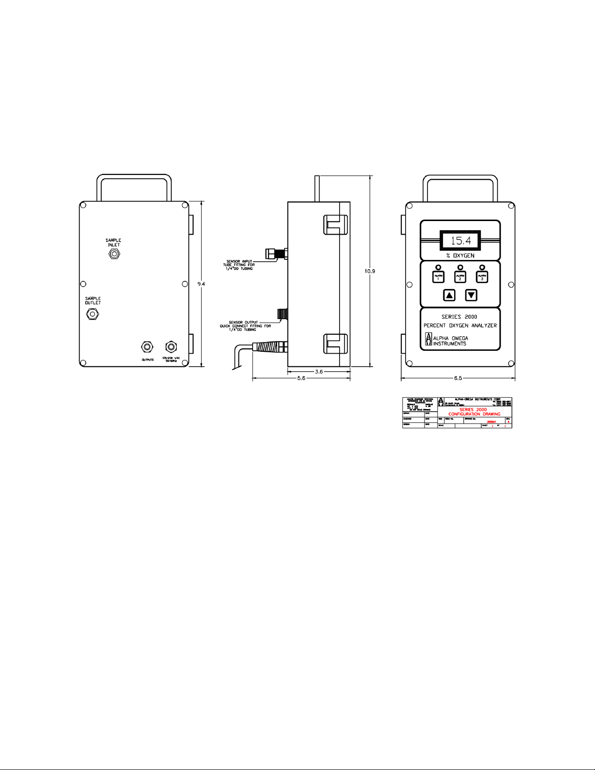
ALPHA OMEGA INSTRUMENTS CORP.
SERIES 2000 PERCENT OXYGEN ANALYZER Instruction Manual
APPENDIX A
BENCH TOP/PORTABLE
CONFIGURATION
PART NUMBER “BTP”
Page 37

ALPHA OMEGA INSTRUMENTS CORP.
SERIES 2000 PERCENT OXYGEN ANALYZER Instruction Manual
APPENDIX B
PANEL MOUNTING CONFIGURATION
PART NUMBERS PNL, PNR, & PTX
FRONT VIEW
Page 38

ALPHA OMEGA INSTRUMENTS CORP.
SERIES 2000 PERCENT OXYGEN ANALYZER Instruction Manual
APPENDIX B
PANEL MOUNTING CONFIGURATION
PART NUMBERS PNL, PNR, PTX
SIDE VIEW
APPENDIX B
PANEL MOUNTING CONFIGURATION
Page 39

ALPHA OMEGA INSTRUMENTS CORP.
SERIES 2000 PERCENT OXYGEN ANALYZER Instruction Manual
PART NUMBERS PNL, PNR, & PTX
REAR VIEW
Page 40

ALPHA OMEGA INSTRUMENTS CORP.
SERIES 2000 PERCENT OXYGEN ANALYZER Instruction Manual
APPENDIX B
PANEL MOUNTING CONFIGURATION
PART NUMBERS PNL, PNR,PTX
PANEL CUT-OUT DETAILS
Page 41

ALPHA OMEGA INSTRUMENTS CORP.
SERIES 2000 PERCENT OXYGEN ANALYZER Instruction Manual
APPENDIX C
REMOTE SENSOR CONFIGURATION
PART NUMBERS BTR & PNR
Page 42

ALPHA OMEGA INSTRUMENTS CORP.
SERIES 2000 PERCENT OXYGEN ANALYZER Instruction Manual
APPENDIX D
EXPLOSION PROOF ELECTRONICS WITH
INTEGRAL OXYGEN SENSOR
PART NUMBER “EXX”
FRONT VIEW
Page 43

ALPHA OMEGA INSTRUMENTS CORP.
SERIES 2000 PERCENT OXYGEN ANALYZER Instruction Manual
APPENDIX D
EXPLOSION PROOF ELECTRONICS WITH
INTEGRAL OXYGEN SENSOR
PART NUMBER “EXX”
SIDE VIEW-ELECTRICAL CONNECTIONS
Page 44
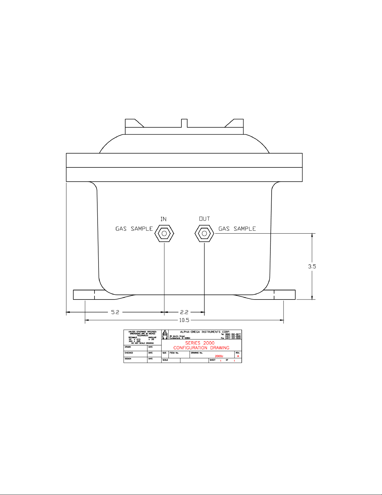
ALPHA OMEGA INSTRUMENTS CORP.
SERIES 2000 PERCENT OXYGEN ANALYZER Instruction Manual
APPENDIX D
EXPLOSION PROOF ELECTRONICS WITH
INTEGRAL OXYGEN SENSOR
PART NUMBER “EXX”
SIDE VIEW-GAS CONNECTIONS
Page 45

ALPHA OMEGA INSTRUMENTS CORP.
SERIES 2000 PERCENT OXYGEN ANALYZER Instruction Manual
APPENDIX E
EXPLOSION PROOF SENSOR CONFIGURATION
PART NUMBER “BTX & PTX”
Note:
Shown
in the
above
diagram is the Series 3000 Analyzer with remote explosion proof sensor enclosure. The Series 3000
explosion proof sensor enclosure is identical dimensionally to the Series 2000 with the exception of
the Gas Input/Output valves.
Page 46
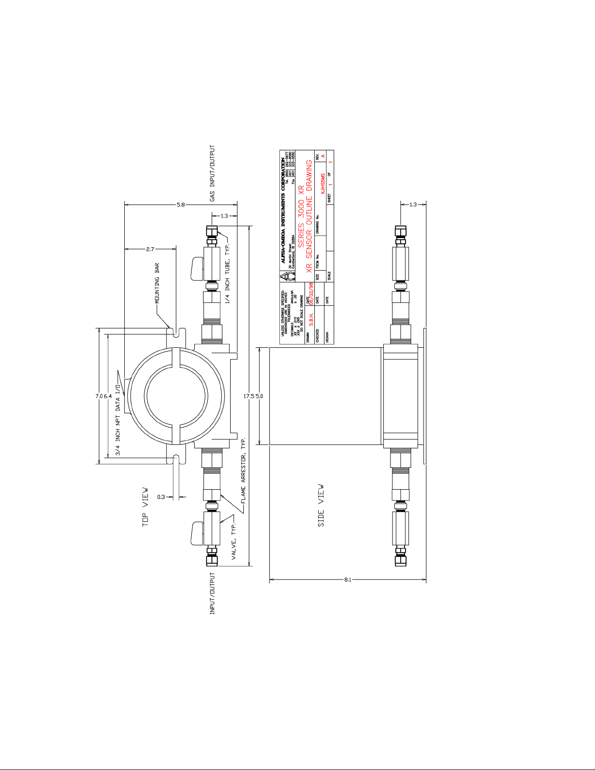
ALPHA OMEGA INSTRUMENTS CORP.
SERIES 2000 PERCENT OXYGEN ANALYZER Instruction Manual
APPENDIX F
EXPLOSION PROOF SENSOR HOUSING
USED WITH THE “BTX & PTX” CONFIGURATIONS
Page 47

ALPHA OMEGA INSTRUMENTS CORP.
SERIES 2000 PERCENT OXYGEN ANALYZER Instruction Manual
APPENDIX G
Note: Shown in the above diagram is the Series 3000 remote explosion proof sensor enclosure. The
Series 3000 explosion proof sensor enclosure is identical dimensionally to the Series 2000 with the
exception of the Gas Input/Output valves.
Page 48

ALPHA OMEGA INSTRUMENTS CORP.
SERIES 2000 PERCENT OXYGEN ANALYZER Instruction Manual
SECTION I - PRODUCT IDENTIFICATION
Manufacturer's Name:
Alpha Omega Instruments Corp
Address
Telephone
Date Prepared
Date Revised
Trade Name
Description
40 Albion Road, Suite 100
401-333-8580
September 3, 1998
April 12, 2001
2SEN and 1SEN
Weak acidic solution encapsulated in plastic housing.
SECTION II - HAZARDOUS INGREDIENTS OF SOLUTION
Lead Acetate, Trihydrate
TLV and PEL are for lead, inorganic dusts and fumes, as Pb
Note: Lead has been reported as causing cancer in laboratory animals, exercise due care.
Acetic Acid, Glacial
NOTE: TLV and PEL are for concentrated (90% - 100%) Acidic Acid, actual solution is less than 50%.
Lead
CAS # 6080-56-4
OSHA/PEL 0.05 mg/m3
ACGIH/TLV 0.15 mg/m3
CAS # 64-19-7
OSHA/PEL 10 PPM
ACGIH/TLV 10 PPM
CAS # 7439-92-1
OSHA/PEL 0.03mg/m3
SECTION III - PHYSICAL & CHEMICAL CHARACTERISTICS
Boiling Point: Not Available Specific Gravity: Not Available
Vapor Pressure: Not Available Vapor Density: Not Available
Evaporation Rate: Not Available Physical State: Liquid
Melting Point: Not Available pH: 3.5 - 7.0 Flash Point: > 100 degrees C
Appearance & Odor: Colorless Liquid: Vinegar like odor
Extinguisher Media: Use water spray, alcohol foam, dry chemical or carbon dioxide
Special Fire Fighting Procedures: Respiratory protection should be used to avoid breathing fumes.
Unusual Fire & Explosion Hazards:
Lead acetate decomposes at boiling point and toxic gases are produced. Acetic acid vapors
may flow along surfaces to distant ignition sources and flash back. Closed containers exposed
to heat may explode.
SECTION IV - REACTIVITY DATA OF SOLUTION
Stability
Stable
Page 49

ALPHA OMEGA INSTRUMENTS CORP.
Hazardous Polymerization:
Will not occur
Conditions to Avoid:
Heat, flame, other sources of ignition
Incompatibles:
Strong acids, strong bases, strong oxidizing agents.
Decomposition Products:
Lead fumes, carbon monoxide, carbon dioxide.
SECTION V - HEALTH HAZARD DATA OF SOLUTION
Lead Acetate Component
Data is for lead, inorganic dusts and fumes as Pb
(TLV/TWA):
0.15 mg/m3
STEL:
Not Established
PEL:
0.05 mg/m3
Toxicity:
Intraperitioneal Rate LD50 for Lead Acetate
Trihydrate is 200 mg/Kg
Carcinogenicity:
This substance is listed as a NTP anticipated human carcinogen
and an IARC animal carcinogen.
Reproductive Effects:
None identified
Effects of Overexposure:
INHALATION:
Tightness and pain in chest, coughing, difficult breathing.
SKIN CONTACT:
Irritation.
EYE CONTACT:
Irritation.
SKIN ABSORPTION:
May be harmful.
INGESTION:
Is harmful and may be fatal, headache, nausea, vomiting,
dizziness, gastrointestinal irritation.
CHRONIC EFFECTS:
Anemia, kidney damage, blurred vision, lead build-up in the
central nervous system.
Target Organs:
GI tract, central nervous system, kidneys, blood, gingival tissue.
Medical Conditions Generally
None identified.
Aggravated by Exposure:
Primary Routes of Entry:
Ingestion, inhalation, eye contact, skin contact, absorption.
Emergency and First Aid Procedures:
INGESTION:
CALL A PHYSICIAN. Give large amounts of water.
INHALATION:
If inhaled, remove to fresh air.
SKIN CONTACT:
In case of contact, flush with water for at least 15 minutes.
EYE CONTACT:
In case of contact, flush with water for at least 15 minutes.
SECTION V - HEALTH HAZARD DATA OF SOLUTION cont'd
Acetic Acid
Data is for concentrated acid.
Threshold Limit value (TLV/TWA)
25 mg/m3
Short term exposure limit (STEL)
37 mg/m3
Permissible exposure limit (PEL)
25 mg/m3
SERIES 2000 PERCENT OXYGEN ANALYZER Instruction Manual
Page 50

ALPHA OMEGA INSTRUMENTS CORP.
SERIES 2000 PERCENT OXYGEN ANALYZER Instruction Manual
Toxicity:
Oral rate LD50 for acetic acid:
Intravenous mouse LD50 for acetic acid:
Skin rabbit LD50 for acetic acid:
Inhalation mouse LD50 for acetic acid:
Carcinogenicity NTP:
IARC
Z List:
OSHA Reg:
3310 mg/kg
525 mg/kg
1060 mg/kg
5620 mg/kg
No
No
No
No
Carcinogenicity:
Reproductive Effects:
Effects of Overexposure:
INHALATION:
SKIN CONTACT:
EYE CONTACT:
SKIN ABSORPTION:
INGESTION:
CHRONIC EFFECTS:
Target Organs:
Medical Conditions Generally
Aggravated by Exposure:
Primary Routes of Entry:
Emergency and First Aid Procedures:
INGESTION:
INHALATION:
SKIN CONTACT:
EYE CONTACT:
None identified
None identified
Severe irritation or burns of respiratory system
Severe burns, may cause dermatitis
Severe burns, permanent eye damage.
None identified
Burns to mouth and throat, nausea, vomiting, gastrointestinal
irritation, diarrhea, shock, may be fatal
Lung damage, teeth damage
Respiratory system, eyes, skin, teeth, lungs.
Respiratory system disease, skin disorders.
Inhalation, ingestion, skin contact, eye contact.
CALL A PHYSICIAN.
Give large amounts of water.
If inhaled, remove to fresh air.
Immediately flush skin with plenty of water for at least 15 minutes.
Immediately flush with plenty of water for at least 15 minutes.
SECTION VI - SPILL AND DISPOSAL PROCEDURES
NOTE: The sensors are sealed, and under normal circumstances, the contents of the
sensors do not present a health hazard. The following information is given as a guide in the
event that a cell leaks.
Steps to be taken in the event of a spill or discharge:
Wear respiratory protection and full protective clothing
Neutralize spill with soda ash or lime
Carefully place material into clean, dry container and cover.
Page 51

ALPHA OMEGA INSTRUMENTS CORP.
Flush spill area with water.
Disposal Procedure:
Dispose in accordance with all applicable federal, state and local environmental regulations, with regards to lead or lead acetate.
EPA Hazardous Waste Numbers:
Lead
D008
Lead Acetate U144 (Toxic Waste)
Acetic Acid, Glacial D001, D002 (Ignitable, Waste)
SECTION VII - ENGINEERING AND WORK PRACTICES CONTROLS
VENTILATION:
Use general or local exhaust ventilation to meet TLV requirements.
RESPIRATORY PROTECTION:
Respiratory protection required if airborne concentration exceeds TLV.
EYE/SKIN PROTECTION:
Safety goggles, uniform, apron, neoprene gloves are recommended.
Protective measures during cell replacement:
Before opening the packaging containing the sensor cell, check the sensor cell for leakage. If the sensor
cell leaks, do not open the container. If there is liquid around the cell while in the instrument, use the
protection listed above in this section.
SECTION VIII - STORAGE AND HANDLING PRECAUTIONS
Storage Requirements: Store in a cool, well-ventilated area.
NOTE: The above data is based on tests and experience which Alpha Omega Instruments, Inc. believes reliable and are
supplied for information purposes only. Alpha Omega Instruments Corp. disclaims any liability for damage or injury which
results for the use of the data and nothing contained there in shall constitute a guarantee, warranty
(including warranty of merchant ability) or representation (including freedom from patent liability) by
Alpha Omega Instruments Corp. with respect to the data, the product described, or their use for any specific purpose,
even if that purpose is known to Alpha Omega Instruments Corp.
SERIES 2000 PERCENT OXYGEN ANALYZER Instruction Manual
Page 52

ALPHA OMEGA INSTRUMENTS CORP.
SERIES 2000 PERCENT OXYGEN ANALYZER Instruction Manual
INSTRUCTION MANUAL ADDENDUM 1
For the Series 2000 Oxygen Analyzer Equipped with
Optional Horn/Strobe Alarm.
If the Series 2000 Oxygen Analyzer has been purchased with an optional Horn & Strobe Alarm
Annunciator (P/N 2000-HnSt-24), please read the following sections. The Horn/Strobe alarm can be
mounted with the Series 2000 electronics or remote from it, and whether the sensor is a local or
remote sensor. Please review the following guidelines when installing the Horn/Strobe Alarm.
Installation and Wiring
Once the Horn & Strobe Alarm Annunciator chassis has been mounted where desired, it can be wired
to the Series 2000 Oxygen Analyzer. To wire the Horn & Strobe Alarm Annunciator, please refer to
Figure 1A of this addendum. Two shielded wires (a twisted pair) will be required to carry the 24 VDC
signal that will energize the unit. Only 60 ma. of DC current is required to energize the audible and
visual signals; however, please be sure to consult with a licensed electrician or person familiar with
wiring practices within your facility location prior to installation and wiring. Please note that the Hn-St
installation wiring is identical whether the Series 2000 uses a local or remote sensor.
All wiring must be done with AC power removed from the main
chassis of the Series 2000 Oxygen Analyzer
Connections to the analyzer are made to the three position barrier strip located on the inside rear
surface of the analyzer. To access the barrier strip, loosen the six screws that hold the clear cover in
place, and lift the clear cover away from the rest of the analyzer. The cover and instrument front panel
may now be lifted and rotated, exposing the inside rear surface of the case where the barrier strip is
located. The wires going to the Horn & Strobe Alarm Annunciator chassis will pass through the far
right cable strain relief and terminate to the barrier strip.
Once the wires are terminated at the analyzer, the wire can be run to the
location of the Horn & Strobe Alarm Annunciator. There is only one cable
strain relief on the annunciator. Remove the cover to the Horn & Strobe
Alarm Annunciator by loosening four outside screws and lifting the cover
and annunciator away from the chassis. Insert the wire through the cable
strain relief, and terminate the black and red wires as indicated in
Figure 1A.
Please note that the Horn & Strobe Alarm Annunciator will activate when Oxygen Alarms A1 or
A2 are active. Oxygen Alarm 3 is left for connection to a local control system, and will not
cause the annunciator to activate. Please be sure to account for the alarm assignments when
setting the alarm values for Oxygen Alarms 1, 2, and 3. System Alarm A4 will not cause the
annunciator to activate, and is left for connection to a local control system.
Page 53

ALPHA OMEGA INSTRUMENTS CORP.
S
T
B
+
JUMPER, RED
JUMPER,BLACK
WIRE, BLACK
1
2
3
4
O
N
HORN & STROBE ALARM ANNUNCIATOR
HnSt-24
WIRE, RED
SERIES 2000 OXYGEN
ANALYZER
WIRE, RED
24 VDC
BLACK RED
WIRE, BLACK
WIRE, RED
WIRE, BLACK
FRONT PANEL
REAR PANEL
25
26
27
28
24
A1-COM
A1-NC
A1-NO
A2-COM
A2-NO
A2-NC
A3-COM
20
21
22
23
A3-NO
A3-NC
NOTE: ALARM 3
IS AVAILABLE
FOR
CONNECTION
TO CONTROL
SYSTEM
WIRE,SHIELD
WIRE,SHIELD
HNSTB-24VDC
HORN&STROBE
ANNUNCIATOR, 24 VDC
SHIELD WIRE to
GRN/YELLOW
GROUND WIRE
WIRE, RED
A
U
D
+
SERIES 2000 PERCENT OXYGEN ANALYZER Instruction Manual
Figure 1A
Page 54

ALPHA OMEGA INSTRUMENTS CORP.
SERIES 2000 PERCENT OXYGEN ANALYZER Instruction Manual
Setting the dBA Sound Level
Locate the four position DIP switch on the alarm module. DIP switch position 1 of this switch sets the
dBA level of the audio alert. When the switch is set to the ON position, high dBA levels of
approximately 85 dB will result; when set to OFF, Standard dBA levels will result which are
approximately 3-4 dB less than the high dBA levels. The unit is shipped with this switch in the “OFF”
position, selecting the STANDARD dBA levels. Please refer to the table below showing the settings
for Switch 1, Position #1 for the setting of dBA levels.
dba Sound Output Level Setting
Decibel Level (DBA) SW1 Switch (POS 1) Setting
Right (shown) is ON
ON = 1
High DBA 1 (POS 1 to ON)
Standard DBA 0 (POS 1 to OFF)
WARNING: IF MULTITONE STROBE SIGNALS ARE OPERATED WITHIN FIFTEEN (15)
INCHES OF A PERSON’S EAR, THEY CAN PRODUCE A SOUND PRESSURE LEVEL THAT
EXCEEDS THE MAXIMUM 120 dBA PERMITTED BY ADA AND OSHA RULES.
EXPOSURE TO SUCH SOUND PRESSURE LEVELS CAN RESULT IN DAMAGE TO A
PERSON’S HEARING.
Selecting the Sound Pattern for the Audible Signal
Eight (8) sound patterns are available from the audible indicator, determined by the settings of
Positions 2-4 of SW1. The table below shows the settings for the available sound patterns. It is not
recommended that either of the “Code 3” settings (horn or tone) be selected for any other use than
Fire Evacuation.
Alarm Tone Settings
Tone Pattern Description
Horn
Bell
March TIme Horn
Code 3 Horn
Code 3 Tone
Slow Whoop
Siren
Hi / Lo
Broadband Horn (Continuous)
1560 Hz. Modulated (0.07 Sec. On/Repeat)
Horn (.25 Sec. On/Off)
Horn (ANSI S3.41 Temporal Pattern)
500 Hz. (ANSI S3.41 Temporal Pattern)
500-1200 Hz. Sweep (4 Sec. On/.5 Sec. Off
600-1200 Hz. Sweep (1 Sec. On/Repeat)
1000-800 Hz. (.25 Sec. On/Alternate)
SW-1 Settings
POS2POS3POS
1 1 1
1 0 1
0 0 1
1 1 0
0 1 1
0 1 0
1 0 0
0 0 0
4
Notes
Fire Evacuation ONLY
Fire Evacuation ONLY
Page 55

ALPHA OMEGA INSTRUMENTS CORP.
SERIES 2000 PERCENT OXYGEN ANALYZER Instruction Manual
INSTRUCTION MANUAL ADDENDUM 2
Optional Internal Data Logger
Note: The standard 0-2V DC output associated with the Series 2000 is used as the input to the
data logger. As a result, this 0-2V DC output is not available for any other use.
Alpha Omega Instrument’s optional internal data logger provides four channels with a data storage
capacity of 43,000 data readings with a user-selectable data capture rate.
The factory default for the Series 2000 is single channel operation. As such, the data logger provides
up to 43,000 data readings for the single channel (oxygen).
Two cables connect the Data Logger to the instrument:
• The first connection is the 0-2V DC oxygen output of the instrument which connects to Input
Channel 1 of the Data Logger (internal).
• The second connection extends the computer connection of the data logger to the outside of
the instrument so that the Data Logger can be launched and data retrieved without opening the
instrument’s cover (external). This is a USB Mini-B style connector.
Please review the following sections carefully; they contain important operational information. Also,
refer to the data logger manual, which provides additional information about the data logger.
The data logger is usually installed in the instrument’s enclosure. However, there are instances when
due to either space constraints or a specific customer request, the data logger may be mounted on the
outside surface or installed remotely.
Data Logger Maintenance
The data logger contains a CR2032 battery that is available from most stores that sell replacement
batteries. Replacing the battery should be performed once every 12 months regardless of how often
the data logger is used.
Note: Prior to removing the battery, remove AC power to the instrument.
Replacing the Data Logger Battery
• To access the data Logger when mounted internally, open the cover of the instrument to
access the device.
• To remove the data logger, unplug the two cables from the data logger, and grasp the device
firmly and slide to the side to disengage the mounting nuts (the screws on the back of the
instrument may need to be loosened to remove the logger). The Data Logger can then be
opened and the coin-shaped battery replaced according to the instructions in the data logger
manual.
• When reinstalling the data logger, position the device over the mounting nuts and slide to the
side to secure in place. (the screws on the back of the instrument may need to be tightened to
secure the logger)
• Replace the cables - the gray plug is located into the Data Channel 1 connector and the USB
computer interface cable plug is located into the bottom connector.
• Close the instrument’s front panel and clear cover.
Page 56

ALPHA OMEGA INSTRUMENTS CORP.
SERIES 2000 PERCENT OXYGEN ANALYZER Instruction Manual
Data Logger Software
• Follow the instructions in the software manual (located on the included CD) to install the
software into the personal computer that you will use for data launching and retrieval. Install
the communications cable from the computer being used (USB-A to USB-Mini-B) to the
analyzer’s data logger connector, located either on the rear or side of the instrument.
• Before you launch the data logger, you should know the following information:
• Data interval desired between points. This interval can range from 1 second between points to
18 hours between points. Estimate the full capacity time by multiplying the data interval times
43,000.
• Types of data acquisition available. One will permit the logger to fill its memory with data and
stop; a second will allow the logger to overwrite the oldest data once filled. When the data is
retrieved, the last 43,000 data points will be downloaded to the PC.
• The data logger needs to be set up to log a 0-2.5V DC signal on Channel 1. If the data logger
is not already set up to do so, this can be accessed by pressing the “Launch” button on the
toolbar. The options under the “Sensors” sections can be used to disable all channels
except Channel 1 and also setup channel 1 for “Adapater Cable 0-2.5V DC” input signal.
• Each data point is time-stamped, using the PC system time. Please make sure that the PC
time and date are correct before taking data.
• Note: Each time the data logger is launched, all old data will be deleted.
• Each time the data is retrieved from the data logger, the option is given to stop data acquisition
or continue logging, if data acquisition is stopped, the logger must be launched again.
• The data stored in the logger is normally a voltage value. The conversion of the 0-2V DC
output from the data logger to a specific oxygen concentration is quite simple. To calculate the
oxygen concentration from the data logger the example used below is based on a single range
of measurement of 0-10% oxygen with an output from the data logger of 0.5V DC.
• The logger has been setup at the factory to automatically convert the data using the
highest instrument range. If the instrument is equipped with multiple ranges, the
instrument must be set to a single range instead of auto ranging. If an instrument range
other than the highest is required for logging, simply follow the instructions provided in
the data logger software manual for setting up a new data conversion range, and also
set the instrument to the same range.
Page 57

ALPHA OMEGA INSTRUMENTS CORP.
SERIES 2000 PERCENT OXYGEN ANALYZER Instruction Manual
INSTRUCTION MANUAL ADDENDUM 3
HIGH VOLUME PUMP
If the analyzer had been supplied with a high volume pump, when operating the
analyzer from a pressurized gas source, disconnect the pump tubing at the flow
meter, fully open the flow meter valve, and TURN THE PUMP OFF.
TANK
Pressurized Gas Source
(calibration or sample)
ANALYZER
Pump
Flowmeter
(Open flow valve)
Pump tubing
(
disconnect here)
Page 58
 Loading...