

Series 1000 Oxygen Deficiency Monitor
User Manual
IMPORTANT! SET OXYGEN ALARM VALUES PRIOR TO OPERATION!
Alpha Omega Instruments Corp.
40 Albion Road, Suite 100
Lincoln, RI 02865
Toll Free (US & Canada) 800.262.5977
Tel: 001-401-333-8580
Fax: 001-401-333-5550
Email: salescontact@aoi-corp.com
Website: www.aoi-corp.com
Version 3.4 (1/12)

Alpha Omega Instruments
This page doesn't exist

Alpha Omega Instruments
©
COPYRIGHT 2006-2009. Alpha Omega Instruments Corp. All rights reserved including the right to reproduce
manual or any portion thereof in any form.
WARRANTY
Alpha Omega Instruments Corp. warrants that delivered products are free from defects in material and
workmanship at the time of delivery to the FOB point specified in the purchase order. Liability under this warranty
is limited to repairing or replacing, at Alpha Omega Instruments' option, items which are returned to it prepaid
within three years (including sensor) from the date of shipment and found to Seller’s satisfaction to have been
defective.
Alpha Omega Instrument's three (3) year sensor warranty provides protection for three years from the date of
shipment of the Series 1000 Oxygen Deficiency Monitor. Any sensor from a Series 1000 Oxygen Deficiency
Monitor that fails under normal use must be returned to Seller prepaid and, if such sensor is determined by
Seller to be defective, Seller shall provide Buyer with a replacement sensor. Buyer must provide the serial
number of the monitor from which the sensor has been removed. If a sensor is found to be defective and a new
one issued, the warranty of the replacement sensor(s) shall not extend beyond the initial warranty period of the
Series 1000 Oxygen Deficiency Monitor, or for a period of one year, whichever is longer. After this, all
replacement sensors will be warranted for a period of one year from the date of shipment. In no event shall
Alpha Omega Instruments Corp. be liable for consequential damages.
NO PRODUCT IS WARRANTED AS BEING FIT FOR A PARTICULAR PURPOSE AND THERE IS NO
WARRANTY OF MERCHANTABILITY.
This warranty applies only if:
(i) the items are used solely under the operating conditions and manner recommended in this manual, product
specifications, or other product specific literature;
(ii)
the items have not been misused or abused in any manner or unauthorized repairs were attempted thereon;
(iii) written notice of the failure within the warranty period is forwarded to Alpha Omega Instruments Corp. and
the directions received for properly identifying items returned under warranty are followed;
(iv) the return notice authorizes Alpha Omega Instruments Corp. to examine and disassemble returned products
to the extent the Company deems necessary to ascertain the cause of failure.
The warranties stated herein are exclusive. THERE ARE NO OTHER WARRANTIES, EITHER EXPRESSED
OR IMPLIED, BEYOND THOSE SET FORTH HEREIN, and Alpha Omega Instruments Corp. does not assume
any other obligation or liability in connection with the sale or use of said products.
Disclaimer of Warranty
Alpha Omega Instruments makes no representation or warranties, either expressed or implied, by or with
respect to anything in this manual, including, but not limited to, implied warranties of merchantability or fitness for
a particular purpose. In no event will Alpha Omega Instruments Corp. be liable for any damages, whether direct
or indirect, special, consequential, or incidental arising from the use of this manual. Some states in the USA do
not allow the exclusion of incidental or consequential damages. Alpha Omega Instruments Corp. also reserves
the right to make any changes to improve the performance of its products at any time and without notice.
i

Alpha Omega Instruments
Important Safety Information
The following safety notices appear throughout this manual.
This symbol calls attention to an imminently hazardous situation which, if not avoided, will result in
death or serious injury.
This symbol calls attention to a potentially hazardous situation which, if not avoided, may result in
death or serious injury.
This symbol calls attention to a potentially hazardous situation, which, if not avoided, may result in
minor or moderate injury. This symbol may also be used to alert against unsafe practices, potential
damage to the instrument or or loss of data.
To avoid the risk of fire or electric shock, do not expose the Series 1000 Oxygen Deficiency Monitor to
rain or water spray unless the enclosure is rated according to the National Electrical Manufacturer's
Association NEMA 4 (IP66)1 rating.
WHEN POWERED, dangerous voltages within the instrument may be of sufficient magnitude to
constitute a risk of electrical shock resulting in injury or death. Leave all servicing to qualified
personnel. Remove ALL Power sources when installing or removing AC power or data signal
connections and when installing or removing the sensor, or electronics.
1
1 The Series 1000 Oxygen Deficiency Monitor complies with National Electrical Manufacturers
Association (NEMA) and IP"XX" European IEC specifications 144 & 529.
ii

Alpha Omega Instruments
RF Disclaimer
This instrument generates and uses small amounts of radio frequency energy, and there may be
interference in a particular installation. If this equipment causes interference to radio or television
reception, try to correct the interference by one of more of the following steps:
1. Reorient the receiving antenna.
2. Relocate the instrument with respect to the receiver.
3. Change the AC outlet of the instrument so the instrument and receiver are on different branch
circuits.
iii

Alpha Omega Instruments
Table of Contents
Important Safety Information.............................................................................................................iii
RF Disclaimer .....................................................................................................................................iv
1 Overview............................................................................................................................................1
1.1 The Series 1000 Oxygen Deficiency Monitor.............................................................................1
1.2 Options and Accessories............................................................................................................2
1.2.1 Battery Backup Option........................................................................................................2
1.2.2 RS-232C Option ................................................................................................................2
1.2.3 RS-485 Option....................................................................................................................2
1.2.4 Remote Mounted Sensor Option........................................................................................3
1.3 Calibration Tool Accessory.........................................................................................................3
1.4 General Specifications...............................................................................................................4
2 Installation.........................................................................................................................................5
2.1 Unpacking the Instrument..........................................................................................................5
2.2 Electrical Installation..................................................................................................................5
2.2.1 Power Source and Line Voltage Setting..............................................................................5
2.2.2 Wiring the AC/DC Power ....................................................................................................6
2.2.3 Wiring the Oxygen Sensor..................................................................................................8
2.2.4 Wiring Alarm Relays...........................................................................................................8
2.2.5 Wiring 4-20 mADC and 0-2 VDC Outputs...........................................................................9
2.2.6 Wiring to the Optional RS-232C or RS-485 Outputs.........................................................10
3 System Description........................................................................................................................11
3.1 Extended Life Electrochemical Sensor ....................................................................................11
3.2 Electronic Data Processing .....................................................................................................12
3.3 Digital Control Center (DCC)....................................................................................................12
3.3.1 Alarms...............................................................................................................................13
3.4 On Board Switch Settings .......................................................................................................14
3.4.1 Fail-Safe Operation ..........................................................................................................14
3.4.2 Alarm 3 Settings ...............................................................................................................14
4 Operation.........................................................................................................................................15
4.1 Preparing for Operation............................................................................................................15
4.2 Selecting AC Voltage...............................................................................................................15
4.2.1 Changing the Voltage Inputs - S2 Jumpers.......................................................................16
4.3 Installing the Monitor................................................................................................................16
4.3.1 Mounting the Monitor on a Wall........................................................................................16
4.4 Operating the Instrument.........................................................................................................16
4.4.1 Power ON........................................................................................................................16
4.4.2 Cold Boot .........................................................................................................................16
4.4.3 Warm Boot........................................................................................................................17
4.5 Battery Backup.........................................................................................................................17
4.6 Operator Controls....................................................................................................................17
4.6.1 Liquid Crystal Display.......................................................................................................17
4.6.2 Oxygen Alarms.................................................................................................................18
4.6.3 Setting the Alarms.............................................................................................................18
4.6.4 Alarm Processing..............................................................................................................18
4.6.4.1 Auto-Clear Operation................................................................................................19
4.6.4.2 Manual Clear Operation...........................................................................................19
iv

Alpha Omega Instruments
4.6.4.3 Timing Out................................................................................................................19
5 Calibrating the Series 1000 Oxygen Deficiency Monitor.............................................................20
5.1 High Altitude Calibration...........................................................................................................20
5.2 Routine Calibration..................................................................................................................20
5.2.1 Calibration with Ambient Air..............................................................................................21
5.2.2 Calibration With Other Gasses.........................................................................................21
5.3 Performing an Initial and/or Routine Calibration Check............................................................21
5.4 Calibration on Ambient Air........................................................................................................22
5.4.1 Calibration Cup (Optional Calibration Tool).......................................................................22
5.4.2 Calibrating from a Gas Cylinder - Effect of Moisture on Calibration .................................23
6 Replacing the Oxygen Sensor ......................................................................................................25
6.1 Replacing the Oxygen Sensor.................................................................................................25
7 Configuring the Optional Remote Sensor.....................................................................................26
8 RS-232C Serial Communications ................................................................................................29
8.1 Baud Rates.............................................................................................................................29
8.2 Standard Commands...............................................................................................................30
8.2.1 'A' Command - Alarm set point with low or high alarm option............................................30
8.2.2 'B' Command - Baud change............................................................................................31
8.2.3 'C' Command....................................................................................................................31
8.2.4 'D' Command ...................................................................................................................32
8.2.5 'E' Command - Enable security with optional passcode....................................................32
8.2.6 'FS' Command - Fail-safe select.......................................................................................32
8.2.7 'H' Command - Help Screen.............................................................................................33
8.2.8 'M' Command - Manually clear all alarms toggle...............................................................33
8.2.9 'O' Command - Output Oxygen Concentration..................................................................34
8.2.10 'Q' Command - Quiet mode (disables the audible alarm)................................................34
8.2.11 'S' Command - Signal mode (enables the audible alarm)................................................34
8.2.12 'V' Command - View current alarms and settings............................................................34
8.3 RS232/485 Connections......................................................................................................35
9 RS-485 - Enhanced Remote Control Command.......................................................................... 36
9.1 RS-485 Protocol......................................................................................................................36
9.2 Enhanced Command Descriptions...........................................................................................37
9.2.1 '\G' Command - Global Set command...............................................................................37
9.2.2 'L' Command - Local name assignment............................................................................39
9.2.3 '\M' Command...................................................................................................................40
9.2.4 “\O' Command - Output Oxygen Concentration................................................................40
9.2.5 '\Q' Command - Quiet Mode select...................................................................................40
9.2.6 '\S' Command - Signal Mode select..................................................................................40
9.2.7 '\U' Command - Use command.........................................................................................40
9.2.8 '\V' Command - View settings...........................................................................................41
10 Internal Data Logger.....................................................................................................................42
10.1 Data Logger Maintenance......................................................................................................42
10.1.1 Replacing the Data Logger Battery.................................................................................42
10.2 Data Logger Software............................................................................................................43
11 Optional 24 VDC Horn/Strobe Alarm...........................................................................................44
11.1 Installation and Wiring............................................................................................................44
11.1.1 Installation.......................................................................................................................44
11.2 Setting the dBA Sound Level..................................................................................................46
v

Alpha Omega Instruments
11.2.1 Selecting the Sound Pattern for the Audible Signal.........................................................47
12 Optional 115 VAC Horn/Strobe Alarm..........................................................................................48
12.1 Installation and Wiring............................................................................................................48
12.1.1 Installation......................................................................................................................49
12.2 Setting the dBA Sound Level.................................................................................................51
12.3 Selecting the Sound Pattern for the Audible Signal................................................................51
Appendix A - ISEN Oxygen Sensor – Material Safety Data Sheet..................................................52
Appendix B - Nickle Hydride Battery Material Safety Data Sheet..................................................57
Appendix C- Effects of Different Oxygen Levels on Humans.........................................................59
vi
Alpha Omega Instruments
1 Overview
1.1 The Series 1000 Oxygen Deficiency Monitor
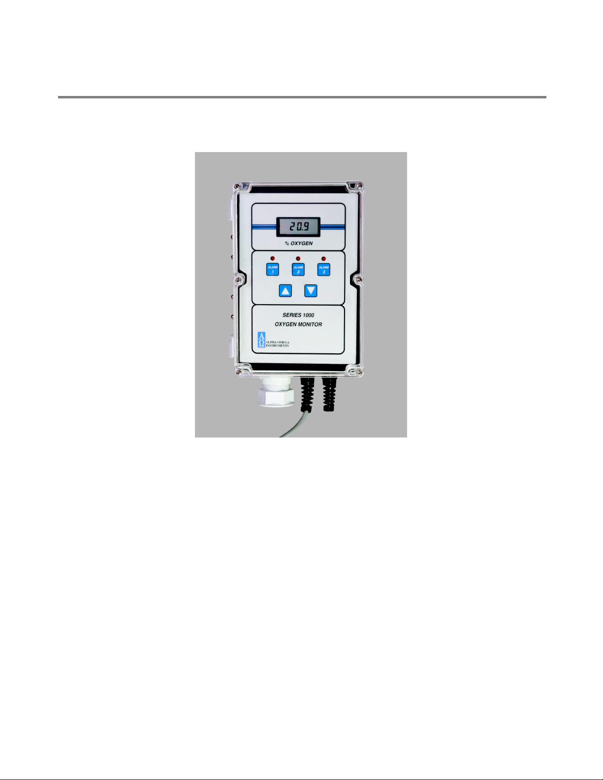
Figure 1-1. The Series 1000 Oxygen Monitor
The Series 1000 Oxygen Deficiency Monitor is a microprocessor controlled instrument with a range of
0-30% . Figure 1-1 shows the standard Series 1000 Oxygen Deficiency Monitor (sensor mounted
integral with electronics).
The microprocessor-controlled instrument includes the following features:
• AC or DC power - 115/230 VAC, 50-60Hz, or with an 18-32 VDC input. Battery backup is
optional (for AC powered instruments only).
• Easy to read liquid crystal display (LCD)
• Polycarbonate enclosure rated general purpose NEMA 1 (IP 30), and watertight, NEMA 4X (IP
66) when used with a NEMA 1 (IP 30) remote sensor enclosure. The optional remote sensor
enclosure can be mounted hundreds of feet from the monitor.
• Easy installation – Holes in the corners of the molded enclosure facilitate installation.
Series 1000 Oxygen Deficiency Monitor Page 1

Alpha Omega Instruments
• Alarm Relays - The instrument is equipped with three oxygen alarm relays and one status
alarm relay. All four relays are Form C (SPDT) types rated at 10 amps at 115/230 VAC and 30
VDC. The relays are user configurable for Fail-safe operation.
• Audible Alarms – The Series 1000 Oxygen Deficiency Monitor has a built-in audible alarm (80
dB) and three red LED's for visual notification of an oxygen alarm condition. Operators can
cancel the audible at any time.
• Standard Analog Outputs - The Series 1000 Oxygen Deficiency Monitor has two standard
analog outputs, 4-20 mADC and 0-2 VDC.
• The Series 1000 Oxygen Deficiency Monitor can also be equipped with optional RS-232C
(maximum transmission distance 50 feet) or RS-485 serial communications for distances of
over 1000 feet.
1.2 Options and Accessories
This section describes available options for the Series 1000 Oxygen Deficiency Monitor.
1.2.1 Battery Backup Option
The factory-installed battery backup option provides backup power to the Series 1000 Oxygen
Deficiency Monitor during a temporary loss of line power. With the backup option installed, the Series
1000 Oxygen Deficiency Monitor will operate for at least 30 minutes under worse case conditions (i.e.
All 4 alarms energized, LED's on, annunciator operating, etc.).
Important: Re-charge batteries 16 hours before initial startup. Batteries are disconnected for
shipment.
The battery pack consists of Nickel Metal Hydride batteries maintained on a trickle charge.
NEVER USE THE BATTERY BACKUP OPTION WHEN THE INSTRUMENT IS POWERED FROM
DC. THIS WILL CAUSE THE BATTERIES TO OVERCHARGE, WHICH MAY CAUSE THE
BATTERIES TO EXPLODE. MAKE SURE ALL WIRING (ALARMS, REMOTE SENSOR, RS-232C,
ETC.) IS COMPLETE BEFORE APPLYING POWER TO THE INSTRUMENT.
1.2.2 RS-232C Option
The factory-installed RS-232C option provides serial communications between the Series 1000
Oxygen Deficiency Monitor and a host system. The maximum distance between monitor and host is
50 feet.
1.2.3 RS-485 Option
The factory-installed RS-485 option provides serial communications between one or several monitors
Series 1000 Oxygen Deficiency Monitor Page 2

Alpha Omega Instruments
and a host system over the same communications channel. The RS-485 format allows both sending
and receiving of signals over distances greater than 50 feet from the host. The maximum distance
recommended between devices is 4,000 feet.
1.2.4 Remote Mounted Sensor Option
This option consists of a factory installed NEMA 1 (IP 30) remote sensor enclosure containing the
oxygen sensor and associated circuitry used to communicate with the read out electronics. When the
remote mounted sensor option is used, the rating for the Series 1000 Oxygen Deficiency Monitor
changes from general purpose, NEMA 1 (IP 30) to NEMA 4X (IP 66) which qualifies it as watertight.
When using the monitor with a battery pack, make sure that all wiring (alarms, remote sensor,
RS-232C, etc.) is complete before applying AC, DC, or battery power to the instrument.
DO NOT USE 24 VDC AS THE SOURCE OF PRIMARY POWER WITH THE BATTERY PACK. THIS
WILL CAUSE THE BATTERIES TO OVERCHARGE WHICH CAN CAUSE THE BATTERIES TO
EXPLODE.
1.3 Calibration Tool Accessory
The optional Calibration Tool is required for calibrating the monitor with gases other than ambient air,
particuarly if there is suspicion that the oxygen concentration in air may be tainted by other gases. The
Calibration Tool contains a tube fitting to deliver the gas, and is designed for low flow conditions (flow
rates of 0.5 to 1.0 liters/minute). The tool attaches to the sensor boss mount to provide a gas tight
inlet.
Series 1000 Oxygen Deficiency Monitor Page 3

Alpha Omega Instruments
1.4 General Specifications
Measurement Range
Accuracy
Sensor Type
Temperature Compensation
Response Time
Sensor Inputs
Sensor Mounting
Display
Input Power
Standard Outputs
Optional Digital Interfaces
Audible Alarm
Audible Alarm Cancel
Oxygen Alarm Relays
Instrument Status Alarm Relay
Open 4-20 mA loop status Alarm
Operating Temperature/Humidity
Electronics Control Unit
Control Unit Dimensions
Optional Remote Sensor Enclosure
Remote Sensor Enclosure
Dimensions
Weight (Control Unit)
Weight (Sensor)
0-30% Oxygen.
±1% of full scale.
Extended Life Electrochemical Sensor.
Standard.
90% of full scale response in <20 seconds.
One.
Either in the electronics enclosure or remotely.
10.2 mm (0.4") high, 4-1/2 digit liquid crystal display.
Resolution 0.1% oxygen.
115/230 VAC, 50-60Hz or 18-32 VDC. Battery backup is
optional for AC powered instruments only.
4-20 mADC and 0-2 VDC.
RS-232C or RS-485 (factory installed).
Internal buzzer (approximately 80dB).
Front panel.
Three (3) SPDT Form C contacts rated 10 A @ 30V
DC/115/230 VAC. Alarm clearing is user configurable for
either manual or automatic.
1 SPDT Form C rated identical to above.
Open collector (drain) output at terminal #10.
5º to 40ºC (40º to 104ºF) and up to 99% (non
condensing).
Light gray polycarbonate with a hinged clear front cover
rated NEMA 1 (IP 30). Available in NEMA 4X (IP 66) with
optional NEMA 1 remote sensor.
239.8 mm (9.44 in.) length, 159.8 mm (6.29 in.) width,
89.9 mm (3.54 in.) height.
Light gray polycarbonate rated NEMA 1 (IP 30).
119.9 mm (4.72 in.) length, 79.8 mm (3.14 in.) width, 84.8
mm (3.34 in.) height.
4.08 kg. (9lbs)
<0.45 kg (<1 lb)
Series 1000 Oxygen Deficiency Monitor Page 4

Alpha Omega Instruments
2 Installation
This chapter describes how to unpack the instrument and perform electrical wiring for power and
monitor options.
2.1 Unpacking the Instrument
To Unpack the Instrument:
1. Carefully remove the instrument from the shipping container and check the outer surfaces for
any damage. Report any damage to Alpha Omega Instruments.
2. Check to make sure all items were shipped. Some items may have been backordered and will
be so noted on the packing slip.
IMPORTANT: Report all damage and missing items to Alpha Omega Instruments within ten
(10) days after receipt of shipment.
3. Locate the screws that attach the clear cover to the polycarbonate enclosure. Loosen the
screws, disengage them, and open the cover to expose the front panel membrane switches.
4. The membrane panel is installed on a hinged metal backing plate that swings out in the same
direction as the cover. Swing out the membrane panel and check for loose or dislodged
components.
NOTE: If there are loose or dislodged components, notify the factory for further instructions.
If all is found to be satisfactory, the installation procedure can begin.
2.2 Electrical Installation
A CERTIFIED ELECTRICIAN SHOULD PERFORM ALL ELECTRICAL INSTALLATION.
ELECTRICAL INSTALLATION MUST COMPLY WITH APPLICABLE FEDERAL, STATE, OR
LOCAL ELECTRICAL SAFETY CODES.
2.2.1 Power Source and Line Voltage Setting
The Series 1000 Oxygen Deficiency Monitor can be powered by a three wire power line cord (included
with shipment) or a conduit into the electrical hub at the bottom of the electronic control unit (conduit
holes can be provided and must be specified at the time of order placement to include diameter size).
Jumper S2 on the printed circuit board determines the line voltage setting. The default setting is for
115 VAC, 50-60Hz operation. If the AC input voltage is changed in the field, please refer to Section
4.2 for instructions.
Series 1000 Oxygen Deficiency Monitor Page 5

Alpha Omega Instruments
2.2.2 Wiring the AC/DC Power
Each connector is equipped with a screw terminal wire holder to facilitate insertion or removal of the
wire from the connector.
To wire the AC/DC Power:
1. Locate the AC Power Terminals - 31, 32, and 33 (refer to Figure 2-1.)
2. Strip away approximately 6.0 mm (1/4 inch) of insulation from each of the three conductors and
then connect AC line, AC neutral, and chassis ground to each connector.
3. Tighten each screw by turning it clockwise to securely fasten each conductor.
4. If the primary power to the instrument is direct current (DC), wire to terminals 29 (BAT+) and 30
(-).
MAKE SURE ALL WIRING (ALARMS, REMOTE SENSOR, RS-232C, ETC.) IS COMPLETE
BEFORE APPLYING ANY POWER TO THE INSTRUMENT.
DO NOT USE 24 VDC AS THE PRIMARY POWER SOURCE WITH THE BATTERY PACK. THIS
CAUSES OVERCHARGING, WHICH MAY CAUSE BATTERIES TO EXPLODE.
Series 1000 Oxygen Deficiency Monitor Page 6

Alpha Omega Instruments
Figure 2-1: Printed Circuit Board
Series 1000 Oxygen Deficiency Monitor Page 7

Alpha Omega Instruments
2.2.3 Wiring the Oxygen Sensor
Oxygen sensor wiring is done at the factory. Refer to section 6.1 Replacing the Oxygen Sensor
regarding how to replace the oxygen sensor.
2.2.4 Wiring Alarm Relays
The Series 1000 Oxygen Deficiency Monitor is equipped with four single pole double throw (SPDT)
Form C contacts rated at 10 amperes @ 30 VDC and 115/230 VAC. All alarm relays are user
configurable with the three oxygen alarms defaulting to factory setting of low oxygen alarms. To
configure any of the three oxygen alarms to be high, see Section 3.4.2 . As a reminder, Alarm 4
which is not displayed as a discrete alarm on the front panel, is the instrument status alarm.
Signal cabling provides access to the control signals generated by the Series 1000 Monitor. The
number of conductors required depends on the number of functions to be monitored.
The technique for wiring to the connectors is identical to that discussed in Section 2.2.2 . The wiring
configuration is as follows:
Terminal Alarm 1 Relay
26 Common Contact
27 Normally Open Contact
28 Normally Closed Contact
Alarm 2 Relay
23 Common Contact
24 Normally Open Contact
25 Normally Closed Contact
Alarm 3 Relay
20 Common Contact
21 Normally Open Contact
22 Normally Closed Contact
Instrument Status Alarm
17 Common Contact
18 Normally Open Contact
19 Normally Closed Contact
Series 1000 Oxygen Deficiency Monitor Page 8

Alpha Omega Instruments
The following table shows wiring configurations for the Series 1000 Oxygen Deficiency Monitor alarms
in both fail-safe and non-fail-safe modes.
Alarm ON
Contacts
shorted for
each Alarm
Fail-safe ON Fail-safe OFF
Relay
High or Low O
Alarm1 /
Relay 1
2
28(NC) to
26(COM)
27(NO) to
26(COM)
High or Low O
Alarm2 /
Relay 2
High or Low O
Alarm3 /
Relay 3
Low Battery or
Instrument
Status/ Relay 4
2
2
25(NC) to
23(COM)
22(NC) to
20(COM)
19(NC) to
17(COM)
24(NO) to
23(COM)
21(NO) to
20(COM)
18(NO) to
17(COM)
To configure the fail-safe or non-fail safe modes, use the DIP switch on the main printed circuit board
(refer to Figure 2-1).
If the instrument is equipped with optional RS-232C or RS-485 communications, the alarms can be
controlled via these comm ports. See the caution note below.
CAUTION:
SHORT THE 4-20MA DC OUTPUT IF NOT IN USE TO AVOID AN OPEN LOOP WARNING VIA
TERMINAL 10 (B-LO)
2.2.5 Wiring 4-20 mADC and 0-2 VDC Outputs
The Series 1000 Oxygen Deficiency Monitor has two standard linear outputs, 4-20 mADC and 0-2
VDC over the instrument's range of 0-30% oxygen. The outputs can be measured simultaneously.
• To wire for the 4-20 mA DC output, wire to terminals 12 (4-20) and 13 (AGND).
• To wire for the 0-2 VDC output, wire to terminals 8 (positive {labeled DAC}) and 9
(negative{labeled AGND}).
Terminals are located on the right side of the printed circuit board (refer to 2-1.)
Note: If a jumper wire is in place between Terminals 12 and 13, remove the jumper wire prior to
using the 4-20 mADC output.
Series 1000 Oxygen Deficiency Monitor Page 9

Alpha Omega Instruments
2.2.6 Wiring to the Optional RS-232C or RS-485 Outputs
The RS-232C and RS-485 options provide serial communications for remote operation and networked
instruments. The monitor can be ordered with either option, but not both.
To wire for either the RS-232C or RS-485, use terminals 14 (TXD) for transmit and 15 (RXD) for
receive. Refer to Chapters 8 and 9 for more information about these options.
Series 1000 Oxygen Deficiency Monitor Page 10

Alpha Omega Instruments
3 System Description
3.1 Extended Life Electrochemical Sensor
The extended life sensor is a lead-oxygen battery that uses a weak acid electrolyte system that
retards passivation of the sensor anode by allowing the products of oxidation to dissolve in the acid
electrolyte. The weak acid electrolyte tolerates over 20 times more lead oxide (PbO) than potassium
hydroxide (KOH) based sensors, renewing the sensor continuously, thereby extending the useful life
of the sensor.
The extended life sensor consists of a lead anode, gold cathode, and a weak acid electrolyte. A gold
electrode is bonded onto a non-porous Teflon® (FEP) membrane. A small amount of oxygen
permeates the membrane and is electrochemically reduced at the gold electrode. A resistor and a
thermistor (for temperature compensation) connects the cathode and anode.
Current flowing through the resistor and thermistor is proportional to the oxygen concentration of the
gas in contact with the Teflon® membrane. The system determines oxygen concentration by
measuring the voltage between the resistor and the thermistor. The two electrode reactions are shown
below:
Cathode: O2 + 4H+ + 4e
Anode: 2Pb + 2H2O
Overall: O2 + 2Pb
The surface of the lead anode is continuously renewed because lead oxide (PbO) is dissolved into the
electrolyte. Since lead oxide generated at the anode is dissolved rather than remaining on the anode,
the output voltage does not decrease.
Lead oxide (PbO) has a maximum solubility level in the weak acid electrolyte. When the electrolyte
becomes saturated with PbO, the sensitivity of the sensor will begin to drop. The system detects this
and notifies the operator that the sensor must be replaced.
In ambient air monitoring applications, carbon dioxide (CO2) that is present will not adversely affect
the sensor's performance. Due to the weak acid electrolyte, CO2 will not react with the electrolyte to
form potassium carbonate as it does with KOH based sensors. As a result, there is no loss in output
due to the presence of CO2.
→
→
→
2H2O
2PbO + 4H+ + 4e
2PbO
Series 1000 Oxygen Deficiency Monitor Page 11

Alpha Omega Instruments
3.2 Electronic Data Processing
Figure 3-1 shown below is a simplified block diagram of the electronics measuring and display systme
for the series 1000 Oxygen Monitor.
Figure 3-1: Electronics Control System
3.3 Digital Control Center (DCC)
The microprocessor-based DCC interfaces with all the inputs and outputs of the system as follows:
• The millivolt output from the oxygen sensor is applied to the input of a buffer amplifier. The
buffer amplifier prevents loading on the sensor and produces a low impedance signal
proportional to the sensor output to the 12 bit analog-to-digital converter input.
• The analog-to-digital converter forms a binary representation of the sensor output for use by
the DCC in all of its decision making functions, and for controlling its outputs. The DCC
processes the sensor input data according to operator inputs as follows:
• The switch bank (SW-6) on the printed circuit board controls the fail-safe condition of
the output alarm relays.
Series 1000 Oxygen Deficiency Monitor Page 12

Alpha Omega Instruments
• The front panel keyboard switches provide controls for adjusting up to three oxygen
level alarm points.
• The optional RS-232C or RS-485 serial interface provides system controls over a network.
• The EPROM (Erasable Programmable Read Only Memory) stores input variables, such as
alarm set points, in a battery backed RAM (Random Access Memory). This RAM stores the
operator-selected alarm set points when power is restored should an AC power outage occur.
• Two analog outputs controlled by the DCC are directly proportional to the sensor output. The
first analog output is an analog voltage output of 0 to 2 VDC, from the digital to analog
converter, over the range of 0 to 30% oxygen. A second analog output tracks the 0 to 2 VDC
output to produce a self-powered 4 to 20 milliamp loop for external data logging and
monitoring. Loop resistance, including wiring, can be as high as 800 ohms even when
operating with the optional Battery Backup. Since the 4 to 20 milliamp loop output chip will
alarm the DCC if an open loop condition exists, this functions connectors must be shorted if
not used.
• A liquid crystal display (LCD) displays the oxygen values over the range of 0 to 30%. The
display also provides operator feedback for setting alarm points and calibrating the monitor.
• An annunciator, also controlled by the DCC, provides audible feedback to the operator
• Three light emitting diodes (LED's) provide visible feedback for system operation.
3.3.1 Alarms
The instrument's audible and visual alarms alert the operator of alarm conditions. The alarm system
consists of:
• Four Form C isolated single pole double throw (SPDT) relays for maximum user flexibility.
• An LED and annunciator for visual and audible alerts. The front panel display and Relay 4
indicate a change in sensor condition and produce an audible alarm.
• If the Series 1000 is equipped with optional battery backup, the sensor status and/or low
battery indication (“LO BATT”) will cause Alarm 4 to change state as well as produce front
panel audible alarms. For loss of AC, (”LOSS OF AC”) and loss of battery (“LOSS OF BATT”),
these conditions will produce an audible alarm but no change in Relay 4.
• An "open collector" output, (open drain output) provides an additional level of operator output
for signaling alarm purposes. This "open drain output", from a 50 volt MOSFET transistor, is
normally open, but will close or short to ground to indicate an alarm condition if the 4 to 20
milliamp loop is open. No audible alarm is associated with an open 4-20 mADC loop.
Series 1000 Oxygen Deficiency Monitor Page 13
Alpha Omega Instruments
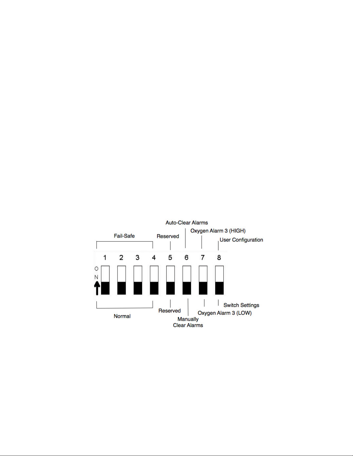
3.4 On Board Switch Settings
NOTE: Please perform the field elevation calibration procedure described in Section 5.1 before
changing any switch settings.
The on-board switch settings provide operator control for fail-safe operation and high/low alarms. This
switch bank has eight (8) individual switches for configuring the Series 1000 as shown in Figure 3-2.
Switch 8 is set to OFF at the factory. This default configuration forces the Series 1000 Oxygen
Deficiency Monitor to read the other switches for power-up or a warm-boot. If Switch 8 is ON ("user
configuration" mode), the Series 1000 Oxygen Deficiency Monitor will be configured using batterybacked configuration information. When set to ON, the monitor ignores the switch settings and boots
according to user-configured settings stored in memory (see Chapter 4).
3.4.1 Fail-Safe Operation
Switches 1-4 control the fail-safe operation for each of the four alarm relays. Each switch must be
turned "ON" to be fail-safe as shown in Figure 3-2. When the system is in the fail-safe mode, an alarm
condition changes the state of the corresponding relay from energized to de-energized upon loss of
AC power. Switches 1 - 4 are set to OFF (normal operation or non fail-safe) at the factory.
Figure 3-2: On-Board Switch Settings For Fail-Safe Operation
3.4.2 Alarm 3 Settings
With Switch 8 in the OFF position, the Series 1000 Oxygen Deficiency Monitor defaults to configuring
Oxygen Alarms 1 and 2 as low alarms, and reads Switch 7 to determine if Oxygen Alarm 3 is either
high or low. Alarm 3 can be configured to default as either a high or low oxygen alarm setting upon
power up.
Series 1000 Oxygen Deficiency Monitor Page 14

Alpha Omega Instruments
4 Operation
4.1 Preparing for Operation
The Series 1000 Oxygen Deficiency Monitor is set to the line voltage specified in the purchase order
at the time of shipment. If the line voltage is not specified, the instrument will be configured for
operation on 115 VAC, 50-60Hz. As soon as the instrument is plugged into the properly rated an AC
outlet (or tied into DC power), within seconds the Series 1000 Oxygen Deficiency Monitor is
operational.
4.2 Selecting AC Voltage
This section describes how to set up the instrument for AC voltage. To power the instrument from an
external DC power source, see the following section.
To change the input voltage:
1. Locate the S2 jumper on the lower left quadrant of the printed circuit board (refer to Figure 2-1:
Printed Circuit Board). The 115 VAC configuration uses a 0.5 ampere slow blow fuse (fuse type
is Wickman 374050004). 230 VAC configuration uses the same kind of fuse. Refer to Step 3.
below for the jumper change required to change AC voltage inputs.
To change the AC voltage inputs:
1. Disconnect the Series 1000 Oxygen Deficiency Monitor from all AC or DC power.
2. Swing out the front panel to access to the main printed circuit board Refer to Section 2.1 ,
Unpacking the Instrument, for instructions).
3. Locate the jumpers on the lower left hand side of the printed circuit board (see Figure 2-1:
Printed Circuit Board) The jumpers are protected by an "L" shaped cover.
Figure 4-1 shows two ways of installing the AC input selection jumpers at S2.
Figure 4-1: Changing the Voltage Inputs - S2 Jumpers
Series 1000 Oxygen Deficiency Monitor Page 15

Alpha Omega Instruments
4.2.1 Changing the Voltage Inputs - S2 Jumpers
To change the AC configuration, remove the jumpers and place them (refer to Figure 4-1 above).
1. Remove the fuse located on the main printed circuit board and replace it with one of the proper
value for the AC input voltage selected.
2. Reassemble the instrument and proceed to the next section.
4.3 Installing the Monitor
Install the Series 1000 Oxygen Deficiency Monitor in the vertical position so that the opening to the
oxygen sensor is facing downwards. The extended life oxygen sensor in the Series 1000 Oxygen
Deficiency Monitor uses an open sensor diffuser that allows free movement of air or other gases into
the sensor by natural diffusion. Sample pumps and aspirators are not required.
BE SURE THE OPENING TO THE OXYGEN SENSOR IS NOT BLOCKED OFF OR COVERED.
THIS CAN PRODUCE INCORRECT OXYGEN READINGS!
4.3.1 Mounting the Monitor on a Wall
To mount the Series 1000 Oxygen Deficiency Monitor on a wall:
1. Open the clear polycarbonate lid to expose the mounting holes at each corner of the
enclosure.
2. Drop a screw through each of the four 0.157" (4 mm) diameter holes and screw them into a
vertical surface (i.e. wall, stanchion, etc.) and tighten. It is recommended that all four corners
of the enclosure be fastened to a vertical surface such as a wall, beam, etc.
4.4 Operating the Instrument
4.4.1 Power ON
The Series 1000 Oxygen Deficiency Monitor does not have an Off/On switch. Power is applied
automatically once the instrument is wired to a power source. Refer to Chapter 2 for wiring
instructions.
4.4.2 Cold Boot
A cold boot ensures that the microprocessor, internal memory, front panel LEDs and audible alarm
are functioning normally. The cold boot sequence is as follows:
1. The instrument's front panel liquid crystal display (LCD) displays a series of dashes in
sequence.
[
¯ ¯ ¯ ¯
][- - - -][
Series 1000 Oxygen Deficiency Monitor Page 16
_ _ _ _
]

Alpha Omega Instruments
2. Each of the three front panel LED's blinks simultaneously for approximately 5 seconds, and the
audible alarm will sound intermittently for as long as the LED's are blinking.
3. An onboard switch setting such as [
| | | | | | | |
|
] then appears on the display. In this example,
Switch 8 is ON and all the others are in the OFF positions.
4.4.3 Warm Boot
A warm boot starts the instrument or restarts the instrument while it is powered ON.
To perform a warm boot and read the internal switch settings:
1. Make sure SW6 Switch 8 is set to the OFF position (see Figure 3-2)
2. On the front panel, press the UP, DOWN, and Alarm 3 buttons simultaneously.
You will see the same sequence as above, however, Switch 8 will indicate LOW. Powering on with
switch #8 in the "OFF" position will cause the Series 1000 Oxygen Deficiency Monitor to default to
factory settings (Alarm 1 and 2 are low alarms) and read the switch bank for all other configurations
(fail-safe modes and Alarm 3 mode).
4.5 Battery Backup
Battery backed Random Access Memory (RAM) saves all values set by the operator. When the
instrument undergoes a cold start, all values are maintained if Switch 8 is set to the ON position (user
configuration mode). Section 3.4 provides instructions for the on-board switch settings.
4.6 Operator Controls
The front panel of the Series 1000 Oxygen Deficiency Monitor contains a 4.5 digit liquid crystal display
(LCD), three (3) alarm set push-button switches, three alarm LED's, and up and down push-button
switches.
4.6.1 Liquid Crystal Display
The LCD displays:
• Oxygen percentage. The percentage of oxygen in the sample being measured. Within
approximately ten seconds after a cold start, the Series 1000 Oxygen Deficiency Monitor will
measure and display the oxygen concentration of the sample gas exposed to the sensor.
Ambient air normally contains 20.9% oxygen by volume.
• High/Low Alarm Status levels. When setting an oxygen alarm value, the values will be
followed by either the letter "H" or "L". indicating either a high or low alarm.
• Battery Status. A Series 1000 Oxygen Deficiency Monitor equipped with the Battery Backup
Option, displays the "LOBAT" message when battery power has reached the point when
normal instrument operation is in jeopardy. It also indicates if there is a loss of battery by
displaying "LOSS OF BATT". When calibrating, a "C" in the display signifies Calibration Mode.
Series 1000 Oxygen Deficiency Monitor Page 17

Alpha Omega Instruments
4.6.2 Oxygen Alarms
The Series 1000 Oxygen Deficiency Monitor is equipped with three (3) oxygen alarms. All are set at
the factory as low alarms at 20.0% O2. Any one of these alarms can be set to HIGH. Please refer to
Section 3.4.2 Alarm 3 Settings , for instructions on how to set Alarm 3 for either high or low operation.
All alarms are user configurable use SW-6, - Switch 8 (refer to 3.4 .On Board Switch Settings ).
4.6.3 Setting the Alarms
1. Assuming that no alarms are currently activated (no front panel LEDs are lit), press the desired
alarm switch on the front panel, "Alarm 1", "Alarm 2", or "Alarm 3" .
The numerical value in the LCD is the existing alarm value associated with that alarm channel.
When the alarm switch is pressed, the LED directly above the switch will light indicating that
channel is in the Alarm Set Mode.
The alarm value in the LCD will be followed by the letter L or H indicating a low oxygen alarm or a
high oxygen alarm, respectively.
2. To change any of the three Oxygen Alarms press the UP and DOWN arrows simultaneously.
3. To set the oxygen alarm values, use the front panel up and down arrows, press the DOWN
arrow to lower the oxygen alarm value or the UP arrow to increase the value. The longer either
arrow is held down, the more rapidly the alarm values will scroll in the display. When the value
in the display is within approximately 0.5% of the desired oxygen set point value, release
pressure on the switch.
4. To obtain the final value, apply momentary pressure to the switch to change values in
increments of 0.1 % oxygen.
5. When finished setting the alarm, press the associated alarm switch. The LED will go off, and
the display will indicate the actual oxygen concentration. If you want to change more than one
alarm value, repeat this procedure using the desired alarm channel.
4.6.4 Alarm Processing
When an alarm event occurs, the Series 1000 Oxygen Deficiency Monitor provides the following
alarms:
1. The LED associated with the specific oxygen alarm illuminates.
2. An audible (approximately 80 dB) alarm sounds.
3. The relay associated with the oxygen alarm changes state.
The alarms may be cancelled by either Auto-Clear or the Manual Clear functions, which are set on
Switch 6 of the SW-6.
Series 1000 Oxygen Deficiency Monitor Page 18

Alpha Omega Instruments
4.6.4.1 Auto-Clear Operation
In the Auto Clear mode (SW-6 Switch 6 is ON), the monitor automatically resets the visual and
audible alarms when the alarm condition clears.
To silence an active alarm when the monitor is in Auto-Clear mode:
1. Press the front panel button associated with the alarm (Alarm 1, Alarm 2, or Alarm 3).
2. To change the setting for this same alarm, press the button a second time. If more than one
alarm is on, the audible alarm will still be canceled.
If you set the alarm to a value that causes an alarm condition, the audible alarm will immediately
sound upon exiting the Alarm Set Mode.
Note: Under Auto-Clear operation, the silenced audible alarm may automatically come back
on if the O2 reading should go out of alarm range and then back into alarm condition.
4.6.4.2 Manual Clear Operation
When SW6 Switch 6 is in the OFF position, the Series 1000 Oxygen Deficiency Monitor is in the
Manual Clear mode. In the manual clear mode, whenever the Series 1000 Oxygen Deficiency Monitor
senses an alarm condition, it will be indicated as previously described. However, if the oxygen level
should return to a non-alarm level, the monitor will not automatically clear.
To manually cancel the audible alarm and alarm condition:
1. Cancel the audible alarm by pushing the appropriate alarm button. This silences the alarm.
2. Push the appropriate alarm button again to clear the alarm condition. If the set point is to
remain the same, simply pushing the appropriate alarm button a third time will clear the alarm.
I
4.6.4.3 Timing Out
The Series 1000 Oxygen Deficiency Monitor will time out and resume normal operation if no
adjustments are made for approximately two (2) minutes. This feature helps ensure that the monitor
is not inadvertently left off-line.
Series 1000 Oxygen Deficiency Monitor Page 19

Alpha Omega Instruments
5 Calibrating the Series 1000 Oxygen Deficiency
Monitor
5.1 High Altitude Calibration
All Series 1000 Oxygen Deficiency Monitors are factory calibrated at 72 feet above sea level. At
elevations higher than 500 feet above sea level, it is essential to perform a startup calibration
adjustment. Calibration negates the effects of higher elevations which produce lower than actual
percent oxygen readings.
To adjust calibration for altitude:
1. Power up the instrument at least 30 minutes before calibration, and make sure it is sampling a
fresh source of air.
2. Press and hold the UP and Alarm 2 switches simultaneously. You will hear a series of beeps
and the display will read "20.9F".
3. Continue holding the two switches until the "F" disappears from the display.
4. Once the "F" has disappeared, release the switches and the process is complete
IMPORTANT: Altitude adjustment is a one-time start-up procedure, however, the instrument
must be re-calibrated if it is moved to an altitude 500 feet higher or lower than the initial
location. Alpha Omega recommends that customers document the date, time, location and
person performing the start-up calibration.
Date:
Time:
Location:
Name of Person
5.2 Routine Calibration
The instrument has an extended life sensor with excellent long term stability characteristics for
minimal routine maintenance. As with all gas monitors and analyzers, it is advisable to periodically
check the overall system calibration. The frequency of these checks is often determined by in-house
calibration protocols. If none exists, Alpha Omega Instruments recommends calibration checks be
done approximately every three to six months. In time, if this frequency is extended, it should never go
beyond checking the monitor at least every six months. Given the importance of the requirement,
calibration checks are prudent. It is advisable that a written log be kept to document the frequency of
calibration checks and/or changes.
Series 1000 Oxygen Deficiency Monitor Page 20

Alpha Omega Instruments
5.2.1 Calibration with Ambient Air
The Series 1000 Oxygen Deficiency Monitor has a measurement range of 0-30% that makes ambient
air (20.9% oxygen by volume) a convenient calibration source. However, if using ambient air, it is
essential that the quality of the ambient air used for calibration be untainted. If the composition of the
air is unknown, calibrate the monitor in a location not affected by the leakage of stored gases. A large
office environment is ideal.
5.2.2 Calibration With Other Gases
If a fresh air supply is not available, instrument air or compressed air (oil free) is the next best choice
as is compressed air from a small cylinder. Do not use plant air as oil vapors and/or water mist
may be entrained in the gas stream and could damage the oxygen sensor and/or adversely
affect oxygen readings.
A calibration gas with a specified concentration of oxygen is another alternative to instrument air or a
compressed air cylinder. The factory recommends a composition of 20.9% oxygen/balance nitrogen.
Most major gas manufacturers can readily supply this calibration gas if instrument or plant air is not
available on site. A single calibration point is required provided the calibration is performed accurately.
No zero gas adjustment is required.
IMPORTANT: The Alpha Omega Instruments Optional Calibration Tool is required when using a
pressured gas to check calibration. Purchase the tool (P/N 1CFN) from the factory, and install it on the
mouth of the oxygen sensor. Maintain the sample flow to the inlet of the calibration fixture between 0.3
and 1.0 liters per minute. Please refer to Section 5.4.1
5.3 Performing an Initial and/or Routine Calibration Check
Note: Make sure the instrument is calibrated at the existing altitude. If the Series 1000 Oxygen
Deficiency Monitor is being used at an elevation higher than 500 feet above sea level, the instrument
must be calibrated to the new altitude before routine calibration. If the elevation correction procedure
has been previously performed, do not repeat it unless elevation conditions have changed.
To Perform a Routine Calibration Check
1. Make sure the instrument has been operating for a minimum of 30 minutes.
2. When measuring a fresh source of ambient air, the reading from the front panel should be at
20.9%, + 0.3% (+ 0.3% is the stated error specification of the Series 1000 Oxygen Deficiency
Monitor).
3. If the monitor is reading within acceptable limits, no further action is required. If the monitor is
not reading within these limits, perform a calibration adjustment as described in the next
section.
Series 1000 Oxygen Deficiency Monitor Page 21

Alpha Omega Instruments
5.4 Calibration on Ambient Air
Important: If using a pressurized gas sample for calibration, please refer to 5.4.1 Calibration Cup
(Optional Calibration Tool) before proceeding.
To perform a calibration adjustment on ambient air:
1. Simultaneously press the front panel buttons labeled Alarm 1, Alarm 2, and Alarm 3.
2. On the front panel display, the letter 'C' appears next to the oxygen value being read to
indicate that this step was executed properly.
3. If the oxygen value displayed is lower than the target value of 20.9%, press the up arrow to
bring the value to 20.9%.
4. If the initial value is higher than 20.9%, use the down arrow to lower the reading.
5. Press Alarm 1, Alarm 2, and Alarm 3 buttons simultaneously again. The letter 'C' will
disappear from the display indicating the calibration sequence has been successfully
completed.
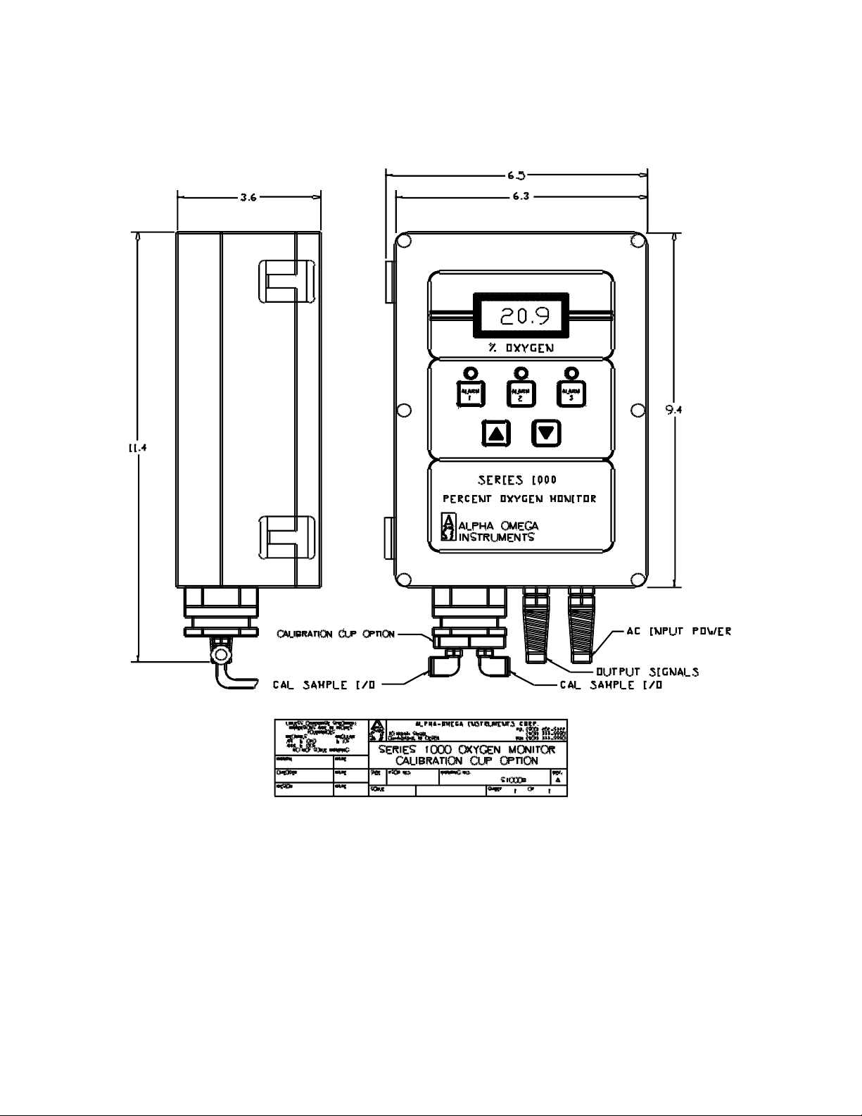
5.4.1 Calibration Cup (Optional Calibration Tool)
To perform a calibration check using instrument air, plant air, or a gas cylinder containing 20.9%
oxygen, use the Optional Calibration Tool. The tool attaches to the bottom of the oxygen sensor
holder. Refer to Figure 5-1, Calibration Cup Option.
To Attach the Optional Calibration Tool:
1. Temporarily remove and save the existing sensor retaining nut.
2. Replace the retaining nut with the Calibration Tool.
3. Using 3/16 ID flex tubing, insert the tubing into one of the two quick-connect gas fittings. Make
sure that the tubing delivering the calibration gas is free of cracks, splits, and defects.
4. Before connecting the gas delivery tube to the inlet of the calibration fixture, place a flow meter
somewhere in line. Maintain the flow rate between 0.3 to 1.0 liters per minute.
Important. Establish a sample flow rate of approximately 0.5 liters per minute before
connecting the tubing to the calibration fixture. This prevents inadvertent over pressurization
that may permanently damage the sensor (not covered under warrany).
Once the calibration gas is flowing to the sensor, allow the reading to come into equilibrium before
proceeding with any adjustments. The factory recommends that the calibration gas should be flowing
to the sensor for at least ten (10) minutes before the readings are monitored to determine if
Series 1000 Oxygen Deficiency Monitor Page 22

Alpha Omega Instruments
equilibrium conditions have been established.
When checking the accuracy of the Series 1000 Oxygen Deficiency Monitor, Alpha Omega
Instruments highly recommends using oxygen concentrations of no lower than 20.9%. In all cases, be
sure to obtain a steady reading for at least five minutes before making adjustments to the
calibration.
6. Once equilibrium has been established, simultaneously press the front panel buttons labeled
Alarm 1, Alarm 2, and Alarm 3.
On the front panel display, the letter 'C' next to the oxygen value indicates that the step is
complete.
• If the oxygen value displayed is lower than the target value of 20.9%, press the up arrow to
bring the value to 20.9%.
• If the initial value is higher than 20.9%, use the down arrow to lower the reading.
7. Press Alarm 1, Alarm 2, and Alarm 3 buttons simultaneously.
The letter C disappears from the display, indicating the calibration sequence is complete.
After using the Calibration Tool, be sure to remove it and re-install the sensor retaining nut
before operating the monitor.
5.4.2 Calibrating from a Gas Cylinder - Effect of Moisture on Calibration
When calibrating the monitor from a gas cylinder be sure to understand the effect of moisture
levels on the oxygen readings as explained in the following section.
When calibrating the Series 1000 Oxygen Deficiency Monitor on a calibration gas from a high
pressure cylinder, the gas can be expected to have essentially zero moisture content. When placing
the Series 1000 in service after calibrating, oxygen readings on ambient air may be slightly (approx.
0.2-0.3%) lower than expected (20.9% is the target value on ambient air).
This difference is due to Dalton’s Law of Partial Pressures that states, “the partial pressure of a gas is
equal to its mole fraction in the mixture multiplied by the total pressure.” Variations in the moisture
content of the ambient air will effect the oxygen concentration readings. As the moisture concentration
(partial pressure) increases or decreases, the partial pressures of the other gases (most notably
oxygen and nitrogen) also change based on changes in their respective partial pressures. For this
reason one can expect variations in the oxygen concentration of ambient air based on changes in
moisture levels (dew point temperatures) from day to day. For example, on a warm, humid summer
Series 1000 Oxygen Deficiency Monitor Page 23
Alpha Omega Instruments
day when moisture levels in the air are high, oxygen levels may decrease slightly (approx. 0.2-0.3%)
due to an increase in moisture.
Figure 5-1: Calibration Cup Option
Series 1000 Oxygen Deficiency Monitor Page 24

Alpha Omega Instruments
6 Replacing the Oxygen Sensor
The Alpha Omega Instruments extended life oxygen sensor is designed to operate for several years
without replacement. However, in time, the sensor's output will drop, and the sensor must be replaced.
More frequent calibration is an indication that the sensor will need replacement soon. Change the
sensor when the Change Sensor message appears on the LCD display. During calibration, an alarm
occurs if the amount of gain (calibration adjustment) exceeds a predetermined limit set at the factory.
An alarm sounds and the Change Sensor message appears on the display.
At the first warning, the instrument will probably function normally. However, it is highly recommended
that the sensor be replaced within a few weeks.. Although the message displayed only once per
calibration cycle (when the preset gain is exceeded), the alarm relay will remain in the alarm state until
the condition has been cleared. Order the sensor directly from the factory.
6.1 Replacing the Oxygen Sensor
Replacing the oxygen sensor clears the Change Sensor alarm.
To replace the Oxygen Sensor:
1. Remove all power (AC or DC) from the instrument.
2. Loosen the six screws that fasten the clear front cover to the polycarbonate enclosure. The
screws should be loose enough to disengage from the control unit allowing access to the front
panel containing the membrane switches.
3. Swing out the membrane panel and locate the sensor which is positioned in the lower left side
of the control unit. The membrane panel is installed on a metal backing plate that is hinged and
swings out in the same direction as the cover.
4. Locate the red connector that connects the sensor and the electronics, and disconnect the
connector.
5. Turn the hex nut on the sensor boss mount counterclockwise to loosen the sensor. It is not
necessary to remove the hex nut - just loosen it.
6. Remove the old sensor and install the new one.
7. With power still off, finger tighten the hex nut and reconnect the connector.
CAUTION: To avoid damage to the sensor, do not over tighten the hex nut. Apply power to the
instrument and calibrate the instrument as described in Chapter 5.
Series 1000 Oxygen Deficiency Monitor Page 25
Alpha Omega Instruments
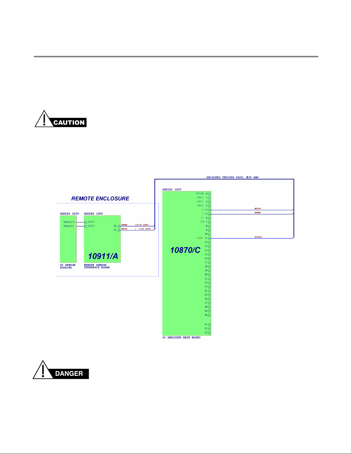
7 Configuring the Optional Remote Sensor
The Optional Remote Sensor is used for applications where the sensor and control electronics are
desired to be in separate locations. The maximum distance between control unit and remote sensor
enclosure is 4,000 feet. If wiring to a remote enclosure, refer to the interconnecting wiring diagram on
the following page (refer to Figures 7-1 and 7-3.
Make sure all wiring (alarms, remote sensor, RS-232C, etc.) are complete before applying AC,
DC, or Battery power to the instrument.
Figure 7-1: Wiring Diagram - Series 1000 Monitor with Remote Sensor
DO NOT USE 24 VDC AS THE SOURCE OF PRIMARY POWER WITH THE BATTERY PACK.
THIS WILL CAUSE THE BATTERIES TO OVERCHARGE. BATTERIES MAY EXPLODE!
Series 1000 Oxygen Deficiency Monitor Page 26
Alpha Omega Instruments
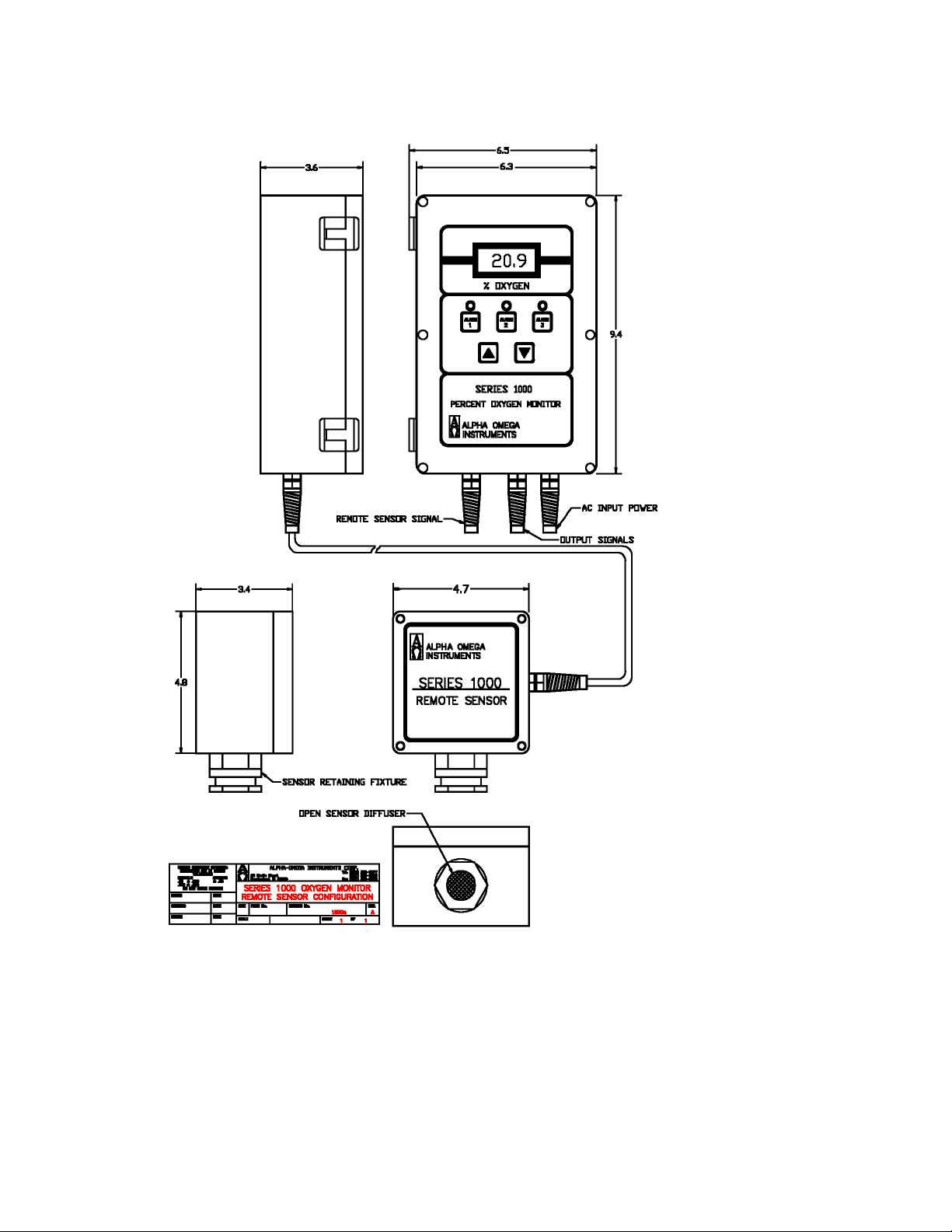
Figure 7-2: Remote Sensor Configuration
Series 1000 Oxygen Deficiency Monitor Page 27
Alpha Omega Instruments
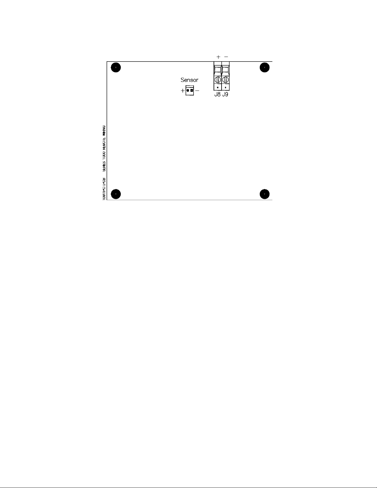
Figure 7-3: Remote Sensor Connections
Series 1000 Oxygen Deficiency Monitor Page 28

Alpha Omega Instruments
8 Optional RS-232C Serial Communications
8.1 Baud Rates
RS-235 Serial communication baud rates are 38400, 19200, 9600, 4800, 2400, 1200, 600, 300, and
150 bps. Rates for RS485, are the same with the exception of 38400 and 19200.
To set the RS-232 baud rate:
1. Make sure that the unit is fully operational. Check for valid oxygen readings on the front panel
LCD of the instrument.
2. Make sure that Switch 5 on the Main board Switch Bank is LOW or OFF. Switch 5 is a factory
switch that should be on only in certain circumstances.
Note: if the unit was shipped with SW5 ON, turn it OFF to set the baud rate. After the baud rate
has been set, move SW5 to the ON position to resume normal operation.
3. Press and hold the UP and DN keys simultaneously. An initial beep followed by a second beep
indicates that the instrument is ready for the next command.
4. The current setting should be displayed on the front panel. If there is no setting indicated,
make sure that you hold the UP and DN keys long enough.
5. Press and hold the UP and DN keys to scroll through available settings choosing the desired
baud rate.
6. When the desired baud rate appears on the display, push the Alarm 3 button to save it in
battery backed memory.
Series 1000 Oxygen Deficiency Monitor Page 29

Alpha Omega Instruments
8.2 Standard Commands
This section describes standard RS-232 commands. Enter letters in either upper or lower case.
Optional strings are case-sensitive.
Standard commands are not case-sensitive. Letters may be in either upper or lower case. The only
exception to this rule is the optional [string] (See note below under the 'D' command description)
Optional commands or strings are shown in brackets. Below is an example Help Screen using the H
Command.
Command Description
Aa=[bb.b][L/H] <Enter> Alarm set
Bccccc <Enter> Baud rate select
C[bb.b] or CAL <Enter> Calibrate ["CAL" defaults to 20.9]
D[string] <Enter> Disable Security
E[string] <Enter> Enable Security
FSd=[ON/OFF/1/0] <Enter> Fail Safe select
H <Enter> Help Screen
M <Enter> Manual clear toggle
O <Enter> Oxygen concentration
Q <Enter> Quiet mode (no beeps at all)
S <Enter> Signal mode (beeps audible)
V <Enter> View current Alarms and settings
Where: a = 1, 2, or 3 for different alarms
bb.b = 0 to 30.0% O2 for alarm setting
L/H = Optionally set to Low or High (H) alarm
ccccc = Baud rate number from 150 to 38400
d = Number designating Relay 1 to 4
ON/OFF/1/0 = 'ON' is the same as '1' etc.
string = String for security protection (see manual)
command
8.2.1
Alarm #1 will be set to go off in the case of the oxygen level dropping below 20%. Type:
A1=20.0L <Enter>
To change Alarm #1 to 18% instead of 20% you could type:
A1=18 <Enter>
Note how the 'L'ow alarm is optional unless changing to 'H'igh? As you can see, the decimal point is
optional too, and if left out defaults to '.0'. Note how the command in the help screen says, "[bb.b]
[L/H]"? Examine the following example:
'A' Command - Alarm set point with low or high alarm option
= Any valid command
Series 1000 Oxygen Deficiency Monitor Page 30

Alpha Omega Instruments
A1=H <Enter>
This is a valid command and will only effect the 'L'ow or 'H'igh status of Alarm 1. To set it back to a
low alarm type:
A1=L <Enter>
The Low alarm is optional unless changing to High. As you can see, the decimal point is optional too,
and if left out defaults to '.0'. Note how the command in the help screen says, "[bb.b][L/H]"? Examine
the following example:
A1=H <Enter>
This is a valid command and will only effect the Low or High (H) status of Alarm 1. To set it back to a
low alarm type:
A1=L <Enter>
8.2.2 'B' Command - Baud change.
To change the baud from 300bps to 9600bps (default), first establish communication at 300bps then
type the following:
B9600 <Enter>
Note that there may be some garbled data output when the instrument responds to the new baud rate.
Now you must change your terminal's baud rate and reestablish communication by pressing <Enter>.
8.2.3 'C' Command
Calibrate to known calibration standard i.e. 5% O2 / balance nitrogen, 15% O2 / balance nitrogen, etc..
Using a calibration gas consisting of 10% O2 / balance nitrogen as an example, type the following:
C10 <Enter>
For room air calibration, take the monitor outside for fresh air or to a known source of 20.9% O2 and
type:
CAL <Enter>
or
C20.9 <Enter>
Note that the monitor defaults to 20.9% if CAL is entered.
Series 1000 Oxygen Deficiency Monitor Page 31

Alpha Omega Instruments
8.2.4 'D' Command
Disable security with optional passcode. (See 'E' Command below for description of security)
In it's simplest form, to disable security protection type:
D <Enter>
Assuming an 'E' Command had been sent with a passcode of "mypass1" (see next command
example) then type the following to disable the security option:
Dmypass1 <Enter>
Note: typing "DMYPASS1" will not disable the instrument if the original passcode was in lowercase!
That means that the 'D' and 'E' commands are CASE SENSITIVE.
8.2.5 'E' Command - Enable security with optional passcode.
To keep others from changing system settings, the 'E'nable Command is supplied as an optional
security measure. In it's simplest form type the following:
E <Enter>
In this example, just type 'E' by itself. This prevents users from inadvertently changing the system
settings. However, if you need to change a setting, type a 'D' command with no passcode. The
following command shows the use of a passcode:
Emypass1 <Enter>
This arms the security system and ignores any requests for system changes until the user disarms the
system with a 'D' Command followed by the correct passcode (See 'D' command above).
8.2.6 'FS' Command - Fail-safe select.
If the alarm relays should be energized in normal operation and released in the case of a power
failure, type the following:
FS1=ON <Enter>
FS2=1 <Enter>
FS3=on <Enter>
fs4=On <Enter>
Note the individual control over each alarm. Also, ON/on/OFF/off or 1/0 can be used to control the
status of each. Commands are not case sensitive. Example: If only Alarm2 needs to be in Fail-safe
mode, then type:
FS1=off <Enter>
FS3=0 <Enter>
FS4=Off <Enter>
This turns off the Fail-safe mode for Alarms 1, 3, and 4.
Series 1000 Oxygen Deficiency Monitor Page 32

Alpha Omega Instruments
8.2.7 'H' Command - Help Screen
Displays a help screen as listed in Section 8.2.
H <Enter>
8.2.8 'M' Command - Manually clear all alarms toggle.
This command toggles between 'M'anual and Automatic clearing of alarms. The alarm is cleared
when the condition causing the alarm has been corrected and the Series 1000 gives no indication that
the alarm was on. The following two examples will explain the difference between 'M'anual and
Automatic clearing of alarms:
Example #1: The Series 1000 monitor is set up to monitor a laboratory full of animals being tested.
In our example, the lab technicians have a suspicion that the reason some animals are expiring
overnight, is because of lack of oxygen! Unfortunately, these technicians don't have any ability to
record the data from the Oxygen monitor, so they set it up for an Alarm 1 set point of 18(L), alarm2 set
point of 19(L), and alarm3 set point of 20%(L). Before they leave for the night, they type:
M <Enter>
The monitor responds with:
Alarms to be cleared Manually
The next morning, the technicians find the monitor reading 20.9%, but alarms are going off! Alarm2
and Alarm3 are both on. This is very meaningful to them, because it means the O2 level in the room
dropped below 19%, but stayed above 18%. This would not have been apparent to them if the alarms
were cleared automatically (See example 2 below)
Example #2: The Series 1000 is set up in an environmental control situation where if the oxygen level
in a room goes below 15%, then a window should automatically open. Also if the oxygen level should
get to 20%, then the window should close and a pump should turn on. First, the user needs to set up
his alarms as follows:
A1=15L <Enter> This sets up a low alarm at 15.0%
A2=20H <Enter> This sets up a high alarm at 20.0%
A3=20H <Enter> This sets up another high alarm at 20.0%
Now the user must toggle the 'M'anual clear command to allow for Automatic clearing:
M <Enter>
Series 1000 responds:
Alarms to be cleared Automatically
Now, assuming the oxygen level to start out at 20.9%, the system could operate as follows:
Alarm1 would be off allowing the window to be closed.
Alarm2 would be on which would tell the window to close.
Series 1000 Oxygen Deficiency Monitor Page 33

Alpha Omega Instruments
Alarm3 would be on which would tell the pump to turn on.
Eventually the oxygen level will drop to under 20% where Alarm 2 and Alarm 3 will automatically shut
off! This could tell the pump to shut off, and allow for the window to be opened by Alarm 1.
Eventually, due to some gas leak in the room, the oxygen level continues to drop below 15% when
Alarm 1 activates and tells the window to open! After a while the oxygen level comes back up past
15% and automatically shuts off Alarm 1. Therefore you have an automatically controlled process.
8.2.9 'O' Command - Output Oxygen Concentration
This command is useful for a quick reading of the Oxygen Concentration. This command returns the
current oxygen reading.
8.2.10 'Q' Command - Quiet mode (disables the audible alarm)
Caution! This disables all sounds - (even from alarms!)
This command is useful if the instrument will be in test mode for awhile, with sensors being removed
and replaced (causing a lot of harmless alarms). Type:
Q <Enter>
This will stay in effect until you type an 'S' command. A message will appear under the 'V'
command displaying the current mode.
8.2.11 'S' Command - Signal mode (enables the audible alarm).
To allow the audible alarms to be heard, simply type the following:
S <Enter>
8.2.12 'V' Command - View current alarms and settings
To view the current status of the Series 1000, type:
V <Enter>
Typical Response:
Alarm Settings
#1:(HI) 22.0 Fail-safe: OFF
#2:(LO) 19.0 Fail-safe: OFF
#3:(LO) 10.0 Fail-safe: ON
#4: N/A Fail-safe: OFF
Channel 1 = 21.0% Oxygen
Series 1000 Oxygen Deficiency Monitor Page 34

Alpha Omega Instruments
Alarm 1 is ON Relay1: Energized
Alarm 2 is OFF Relay2: De-energized
Alarm 3 is OFF Relay3: Energized
Conditions
AC inp: ok 4-20mA: ok Open Collector output: off
Batt: ok (22) Sensor: ok Aux. Relay: De-energized
Alarms to be cleared MANUALLY
Signal Mode
Commands that affect the output of the 'V' command are as follows:
•
• 'A' commands will update the Alarm Settings
• 'FS' commands will update the Fail-safe settings ON or OFF
• 'Q' & 'S' commands will update the comment indicating the status of the 'Q'uiet / 'S'ignal mode
• 'M' commands will toggle the word following the phrase, "Alarms to be cleared ",
between 'manually' and 'automatically'.
Note: The number in parenthesis next to the Battery condition is simply the voltage detected
by the battery circuit. This can be used for making sure the battery is fully charged.
8.3 RS232/485 CONNECTIONS
Connect the Series 1000 to a terminal or computer as shown in Figure 8-1.
Figure 8-1: RS-232/485 Connections
Note: If you have an RS485 output and have trouble communicating, try tipping over the input
and output lines. Some are called T+ / T- or maybe A / B. Whatever the case, the
communications link will not work unless these are correct.
Series 1000 Oxygen Deficiency Monitor Page 35

Alpha Omega Instruments
9 RS-485 – Optional Enhanced Remote Control
Command
9.1 RS-485 Protocol
Please read the section on RS232C first to familiarize yourself to the command structure. All
commands under RS485 are either exactly the same or have slight enhancements over RS232C.
This section describes the enhancements associated with the RS485 protocol.
Below is a sample 'H'elp Screen using the '\H' Command.
Command Description
\Aa=[bb.b][L/H] <Enter> Alarm set
\Bccccc <Enter> Baud rate select
\C[bb.b] or \CAL <Enter> Calibrate [”CAL” defaults to 20.9%]
\D[string] <Enter> Disable Security
\E[string] <Enter> Enable Security
\FSd=[ON/OFF/1/0] <Enter> Fail-safe select
\Gcommand <Enter> Global set (be careful here)
\H <Enter> Help Screen
\L[name] <Enter> Local Name OR Number
\M[name] <Enter> Manual clear toggle
\O[name] <Enter> Oxygen Concentration
\Q[name] <Enter> Quiet mode (no beeps at all)
\S[name] <Enter> Signal mode (beeps audible)
\U[name] <Enter> Use analyzer with 'name' for all
cmds
\V[name] <Enter> View current Alarms and settings
Where: a = 1, 2, or 3 for different alarms
bb.b = 0 to 30.0% O2 for alarm setting
L/H = Optionally set to 'L'ow or 'H'igh alarm
ccccc = Baud rate number from 150 to 9600
d = Number designating Relay 1 to 4
ON/OFF/1/0 = 'ON' is the same as '1' etc.
name = String for accessing multiple units (see manual)
string = String for security protection (see manual)
command = Any valid command (WARNING: G will act on all
units!)
Please note that there is an extra character - a backslash ('\') - before each command. This prevents
conflicts between individual Series 1000's.
Series 1000 Oxygen Deficiency Monitor Page 36

Alpha Omega Instruments
RS485 has three new commands: 'G'lobal, 'L'ocal, and 'U'se. The first one is the 'G' Command. As it
states above, this is the 'G'lobal Set command. This command is very powerful and is discussed in
the following sections.
RS485 provides the ability to connect multiple Series 1000's together and communicate to them
simultaneously. Therefore, it may become necessary or convenient to set certain points 'G'lobally.
Instead of setting all instruments up one by one, use the 'G'lobal Command to control all Series 1000
units at the same time!
Each command will be discussed here, taking into consideration that there is most likely more than
one unit to be controlled over the RS485 communications lines (twisted pair).
'\A' Command - Same as RS232
'\B' Command - Same as RS232
'\C' Command - Same as RS232
'\D' Command - Same as RS232
'\E' Command - Same as RS232
'\F' Command - Same as RS232
'\H' Command - Same as RS232
'\O' Command - Same as RS232
9.2 Enhanced Command Descriptions
9.2.1 '\G' Command - Global Set command.
This command will cause all units tied into the RS485 communications line to respond to
whatever command comes after it. For example, typing:
\G <Enter>
will do nothing! This is because no command was given after the 'G'. However, typing:
\GA1=20.5h <Enter>
will set up every Series 1000 connected to the RS485 line to have a High Alarm1 Setting of 20.5%
Now let's try the 'G' command with the 'B' command for setting the baud rate. This is a handy little
time saver! For instance, to set all units to 9600bps just type:
\GB9600
Or in other words, "Global Baud 9600". Make sure you change your terminal baud rate after using a
'B' command.
\GC <Enter> will not do anything.
Globally Calibrating is not allowed
Series 1000 Oxygen Deficiency Monitor Page 37

Alpha Omega Instruments
The next two commands function just like RS232C:
\GD[string] and
\GE[string]
Just remember, if you are adding units to the RS485 line, and you don't make sure of your security
codes, you could end up with multiple security codes! To be sure, have all units on line before
enabling a global security code.
If you need all instruments to operate in the Fail-safe mode, just use the 'G'lobal command:
\GFS1=1 <Enter>
\GFS2=1 <Enter>
\GFS3=1 <Enter>
\GFS4=1 <Enter>
Note how each Alarm is treated individually. The following commands are not available:
\GH <Enter> does nothing.
\GI <Enter> does nothing.
\GL <Enter> does nothing.
\GQ <Enter> Global Quiet (disables ALL the audible alarms.
Warning! This disables all sounds - even
from alarms!)
No optional name is required and will cause the Series 1000 (if enabled) to respond with an 'Error!'
message if supplied. (See description of 'Q' command below).
Preceding this command with the 'G'lobal command does exactly what you would expect. 'G'lobally
'Q'uiet all audible sounds. See the 'S'ignal command below for setting the audible sounds back to
normal.
To make all alarms audible, type the following command:
\GS <Enter>
This puts all Series 1000's into 'S'ignal mode. This means that any alarm condition will result in an
audible alarm signal. No other commands are available for 'G'lobal setting.
\GU <Enter> does nothing.
\GV <Enter> does nothing.
Series 1000 Oxygen Deficiency Monitor Page 38

Alpha Omega Instruments
9.2.2 'L' Command - Local name assignment.
This command allows the user to name each Series 1000 that might be on the RS485
communications line. For instance, an example might be that there are two rooms that need to be
monitored using a Series 1000 in each room. From the factory, the Series 1000 is set up to have a
blank 'name'. This is equivalent to typing:
\L <Enter>
If the unit has been enabled using the 'U' command (see below) or has been set up to the factory
default, the instrument will respond:
'' O.K. Note: be careful if there are spaces such as:
' ' O.K. This has a space for the name.
The unit's name is displayed in single quotation marks. Note how the name is blank above.
In our example, we want to put two Series 1000's on line. First connect ONE Series 1000 to the
RS485 line, and get it up and running. After the unit is responding, type the following just as an
example:
\L Unit#1 <Enter>
This returns a message stating:
'' changed to: ' Unit#1'
' Unit#1' O.K.
You can substitute the above, "Unit#1" with any string. Shorter strings save keystrokes when
accessing the unit. Now type the following:
\U <Enter> See 'U' command below for description.
This basically 'disables' Unit#1 so we can communicate with the next unit we put on the line.
To add another unit, connect the second Series 1000 to the line. If you haven't already, you may have
to type 'L' followed by <Enter> (Factory Default) to communicate with the new unit that was just put
on the line. (Note: if the unit does not respond then a factory boot may be necessary - See the
section on Front panel) At this time you can name the second unit. Maybe it would look something
like this:
\L Unit#2 <Enter>
Series 1000 Oxygen Deficiency Monitor Page 39

Alpha Omega Instruments
If you put two or more units on an RS485 line with the same name and ask for output,
anything can happen! You can change the currently responding unit's name, just don't
set it to a name that currently exists because the next time you type "Uname", you will
select two units at one time!
9.2.3 '\M' Command
Manual / Automatic clearing of alarms (See Chapter 4 for description).
The 'name' of the unit can be used as a variable. For instance, no matter what unit is enabled and
responding to commands, you can address a specific unit for toggling this function as follows:
\M#1 <Enter>
If a unit with the 'name' "#1" assigned to it exists, then only that unit will act upon the command. Note:
Only the unit that is enabled can respond, so when using this addressing scheme you may want to
verify the command by giving it a 'V'name command (See below).
9.2.4 “\O' Command - Output Oxygen Concentration
This command is useful for a quick reading of the Oxygen Concentration. All that is returned is the
present reading in percent oxygen.
9.2.5 '\Q' Command - Quiet Mode select
Same enhancement as above in that you can selectively 'Q'uiet any unit by following the command
with a valid unit name.
9.2.6 '\S' Command - Signal Mode select
Same enhancement as above.
9.2.7 '\U' Command - Use command.
This command is used for selecting a different Series 1000 that has already been set up using the 'L'
command. For instance, using the above example of Unit#1 and Unit#2, to access Unit#1 you would
type:
\U Unit#1
The system responds with:
Using: ' Unit#1'
Note the 'extra' space after the single quote at the beginning of the string. This is not mandatory and
Series 1000 Oxygen Deficiency Monitor Page 40

Alpha Omega Instruments
can be removed by renaming it using the 'L' command as follows:
LUnit#1 <Enter> Note: no space between 'L' and 'U'
9.2.8 '\V' Command - View settings
This has the same enhancement as the 'M', 'Q', and 'S' commands and can be used to verify that each
of those commands work properly. For example: With two units, one named "One" and the other
named "Two" you could do the following:
\UOne <Enter>
This selects unit "One". Now lets check the status of unit "Two":
\VTwo <Enter>
We will just notice that part of the 'V'iew screen shows:
Alarms to be cleared MANUALLY
Now try changing the MANUAL clearing to AUTOMATIC without 'U'sing unit #2:
\MTwo <Enter>
\VTwo <Enter>
Now we can see that the 'V'iew screen shows:
Alarms to be cleared AUTOMATICALLY
Note that while we entered these commands the unit would respond to an <Enter> with:
'One' O.K.
That means you could set up all your parameters for unit "One" and still use the 'M', 'Q', and 'S'
commands on other units without having to type "UTwo", then the desired command.
Series 1000 Oxygen Deficiency Monitor Page 41

Alpha Omega Instruments
10 Optional Internal Data Logger
Alpha Omega Instrument’s optional internal data logger provides four channels with a data storage
capacity of 32,000 data readings with a user-selectable data capture rate.
The factory default is single channel operation. As such, all 32,000 data readings are available for that
channel. When using two channels, the data logger provides up to 16,000 data readings.
Two cables connect the Data Logger to the instrument:
• The 0-2 VDC output connects the instrument’s main printed circuit board to Input Channel 1 of
the Data Logger.
• The second connection extends the computer connection to the outside of the instrument so
that the Data Logger can be launched and data retrieved without opening the instrument’s
cover.
If the product purchased from Alpha Omega Instruments is equipped with a data logger, please review
the following sections carefully; they contain important operational information. Also, refer to the data
logger manual, which provides additional information about the data logger.
The data logger is usually installed in the instrument’s enclosure However, there are instances when
due to either space constraints or a specific customer request, the data logger may be mounted on the
outside surface or installed remotely.
10.1 Data Logger Maintenance
The data logger contains a CR2032 battery that is available from most stores that sell replacement
batteries. Replacing the battery should be performed once every 12 months regardless of how often
the data logger is used.
Note: Prior to removing the battery, remove AC power from the instrument.
10.1.1 Replacing the Data Logger Battery
To replace the Data Logger battery:
1. To access the data Logger when mounted internally, open the cover of the instrument and
swing the front panel of the analyzer open to access the device.
2. To remove the data logger, unplug the two cables from the data logger, and grasp the device
firmly and lift with a slight twisting motion to disengage the 3M® fastening material. The Data
Logger can then be opened and the coin-shaped battery replaced according to the instructions
in the data logger manual.
3. When reinstalling the data logger, position the device over the mating patch of 3M fastening
material, and push on the data logger to engage the material.
Series 1000 Oxygen Deficiency Monitor Page 42

Alpha Omega Instruments
4. Replace the cables - the gray slender plug is located into the top connector (Data Channel
One), and the larger black computer interface cable plug is located into the bottom connector
(the connector receptacle with the metal ring).
5. Close the instrument’s front panel and clear cover.
10.2 Data Logger Software
Follow the instructions in the attached software manual to install the software into the personal
computer that you will use for data launching and retrieval. Install the communications cable from the
computer being used (DB-9 connector) to the analyzer’s data logger connector, located on the right
side of the instrument.
Before you launch the data logger, you should know the following information:
• Data interval desired between points. This interval can range from 0.5 seconds between
points to over 9 hours between points. Estimate the full capacity time by multiplying the data
interval times 32,000.
• Types of data acquisition available. One will permit the logger to fill its memory with data and
stop; a second will allow the logger to overwrite the oldest data once filled. When the data is
retrieved, the last 32,000 data points will be downloaded to the PC.
Each data point is time-stamped, using the PC system time. Please make sure that the PC time and
date are correct before taking data.
Note: Each time the data logger is launched, all old data will be deleted.
Each time the data is retrieved from the data logger, data acquisition is stopped, and the logger must
be launched again.
IMPORTANT: If your instrument is equipped with autoranging, make sure that this feature is
OFF and select only one range before logging data. Refer to the data logger manual for more
information.
Series 1000 Oxygen Deficiency Monitor Page 43
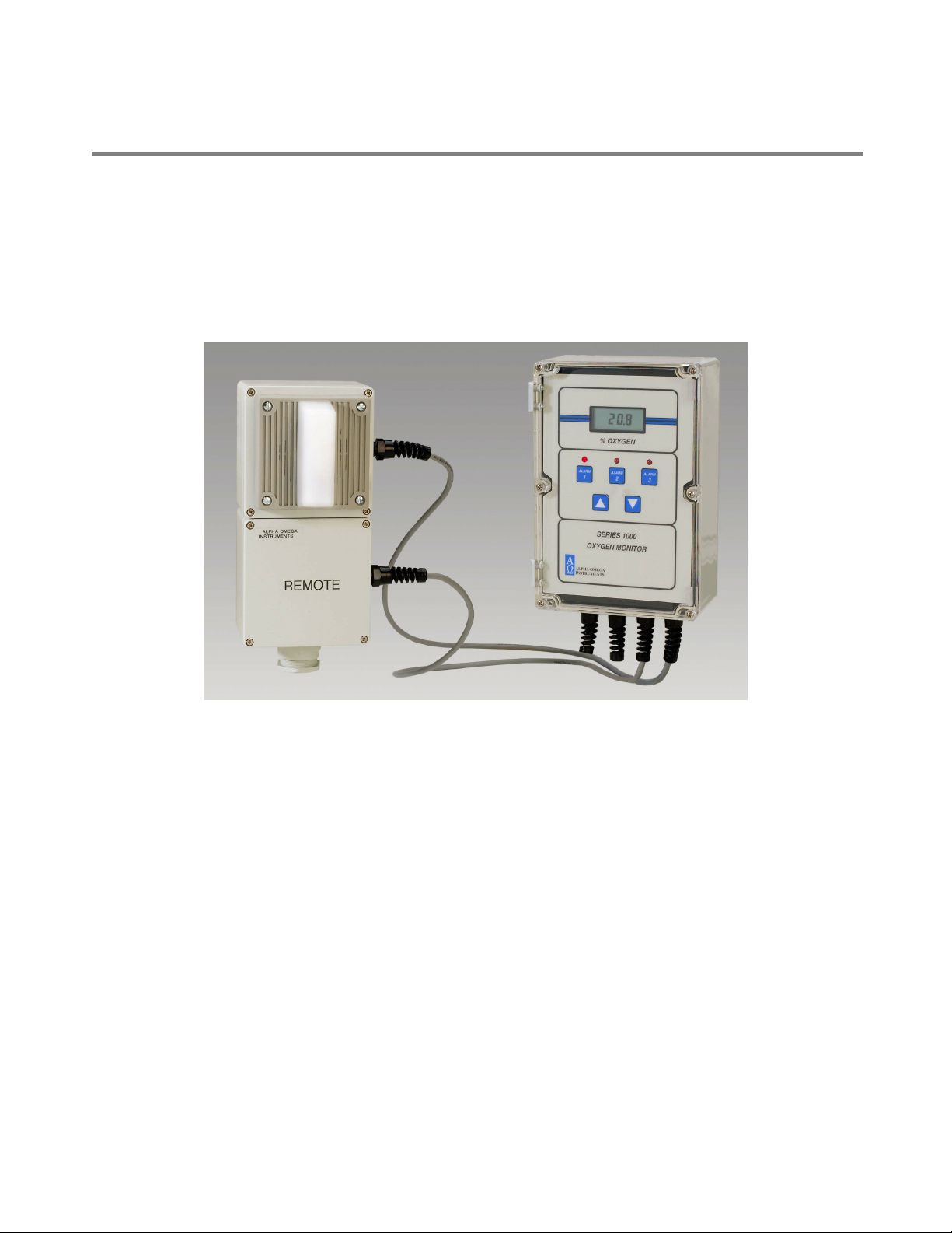
Alpha Omega Instruments
11 Optional 24 VDC Horn/Strobe Alarm
The following sections describe how to wire an an optional 24 VDC powered Horn & Strobe Alarm
Annunciator (P/N 1000-HnSt-24).
The Horn/Strobe alarm can be mounted with the Series 1000 electronics or in a remote location with
or without a remote sensor. Please review details of purchase order to determine the exact
configuration of your system.
Figure 11-1: Optional Horn/Strobe Alarm together with Optional Remote Sensor
11.1 Installation and Wiring
After mounting the Horn & Strobe Alarm Annunciator chassis in the desired location, wire it to the
Series 1000 Oxygen Deficiency Monitor. Figure 11-2 provides wiring information.
11.1.1 Installation
Consult with a licensed electrician or person familiar with wiring practices within your facility location
prior to installation and wiring.
Series 1000 Oxygen Deficiency Monitor Page 44

Alpha Omega Instruments
Two shielded wires (a twisted pair) will be required to carry the 24 VDC signal that will energize the
unit. Approximately 330 mA of DC current is required to energize the audible and visual signals.
Please note that the Hn-St installation wiring is identical whether the Series 1000 uses a local or
remote sensor.
REMOVE ALL POWER FROM THE MAIN CHASSIS OF THE Series 1000 Oxygen Deficiency
Monitor BEFORE WIRING.
To connect the Horn/Strobe Alarm:
1. Locate the three position barrier strip on the inside rear surface of the analyzer.
2. To access the barrier strip, loosen the six screws that hold the clear cover in place, and lift the
clear cover away from the rest of the analyzer.
3. Lift and rotate the instrument front panel to expose the inside rear surface of the case where
the barrier strip is located. The wires going to the Horn & Strobe Alarm Annunciator chassis
will pass through the far right cable strain relief and terminate to the barrier strip.
4. Once the wires are terminated at the monitor, the wire can be run to the location of the Horn &
Strobe Alarm Annunciator. There is only one cable strain relief on the annunciator.
5. Remove the cover to the Horn & Strobe Alarm Annunciator by loosening four outside screws
and lifting the cover and annunciator away from the chassis. Insert the wire through the cable
strain relief, and terminate the black and red wires as shown in Figure 11-2.
NOTE: The Horn & Strobe Alarm Annunciator will activate when Oxygen Alarms 1 or 2 are
active. Oxygen Alarm 3 is reserved for connection to a local control system, and will not cause
the annunciator to activate. Please be sure to account for the alarm assignments when setting
the alarm values for Oxygen Alarms 1, 2, and 3. System Alarm 4 will not cause the
annunciator to activate, and is also reserved for connection to a local control system
The Candela (light intensity) as been factory set and fixed at 75.
Series 1000 Oxygen Deficiency Monitor Page 45
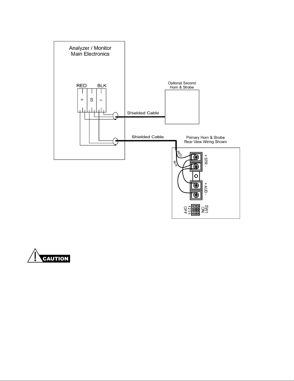
Alpha Omega Instruments
Figure 11-2: DC Powered Horn and Strobe
If the terminal block inside the analyzer/monitor is equipped with single entry terminals it is
configured for a single Horn and Strobe unit. DO NOT connect more than one Horn and Strobe
to single entry terminals. The system will not function correctly.
11.2 Setting the dBA Sound Level
The following section describes how to set the decibel sound level on the Optional Horn and Strobe
unit.
To set the sound level:
1. The horn associated with the optional Horn & Strobe Annunciator has a standard setting of 87
dB from the factory and the switch (Figure 11-3) is set to the OFF postion.
Series 1000 Oxygen Deficiency Monitor Page 46

Alpha Omega Instruments
• To set higher decibel levels of approximately 92dB, set DIP Switch Position 1 to ON
Figure 11-3: Decibel Level Sound Output Settings
MULTI-TONE STROBE SIGNALS AT CLOSE RANGE (FIFTEEN INCHES OR LESS) CAN
PRODUCE A SOUND PRESSURE LEVEL THAT EXCEEDS THE MAXIMUM SAFE DECIBEL
LEVEL PERMITTED BY ADA AND OSHA RULES. EXPOSURE TO THESE SOUND PRESSURE
LEVELS CAN DAMAGE HEARING. DO NOT OPERATE THE UNIT WITHIN FIFTEEN (15) INCHES
OF YOUR EAR, AND TAKE APPROPRIATE PRECAUTIONS WHEN MOUNTING AND
CONNECTING THE UNIT.
11.2.1 Selecting the Sound Pattern for the Audible Signal
Eight (8) sound patterns are available from the audible indicator, determined by the settings of
Positions 2-4 of SW1. The following table shows the settings for the available sound patterns. It is not
recommended that either of the “Code 3” settings (horn or tone) be selected for any other use than
Fire Evacuation.
Alarm Tone Settings
Tone Pattern Description
Horn
Bell
March TIme Horn
Code 3 Horn
Code 3 Tone
Slow Whoop
Siren
Hi / Lo
Broadband Horn (Continuous)
1560 Hz. Modulated (0.07 Sec. On/Repeat)
Horn (.25 Sec. On/Off)
Horn (ANSI S3.41 Temporal Pattern)
500 Hz. (ANSI S3.41 Temporal Pattern)
500-1200 Hz. Sweep (4 Sec. On/.5 Sec. Off
600-1200 Hz. Sweep (1 Sec. On/Repeat)
1000-800 Hz. (.25 Sec. On/Alternate)
SW-1 Settings
POS2POS3POS
1 1 1
1 0 1
0 0 1
1 1 0
0 1 1
0 1 0
1 0 0
0 0 0
4
Notes
Fire Evacuation ONLY
Fire Evacuation ONLY
Table 1. Table 11-1. Alarm Tone Settings
Series 1000 Oxygen Deficiency Monitor Page 47
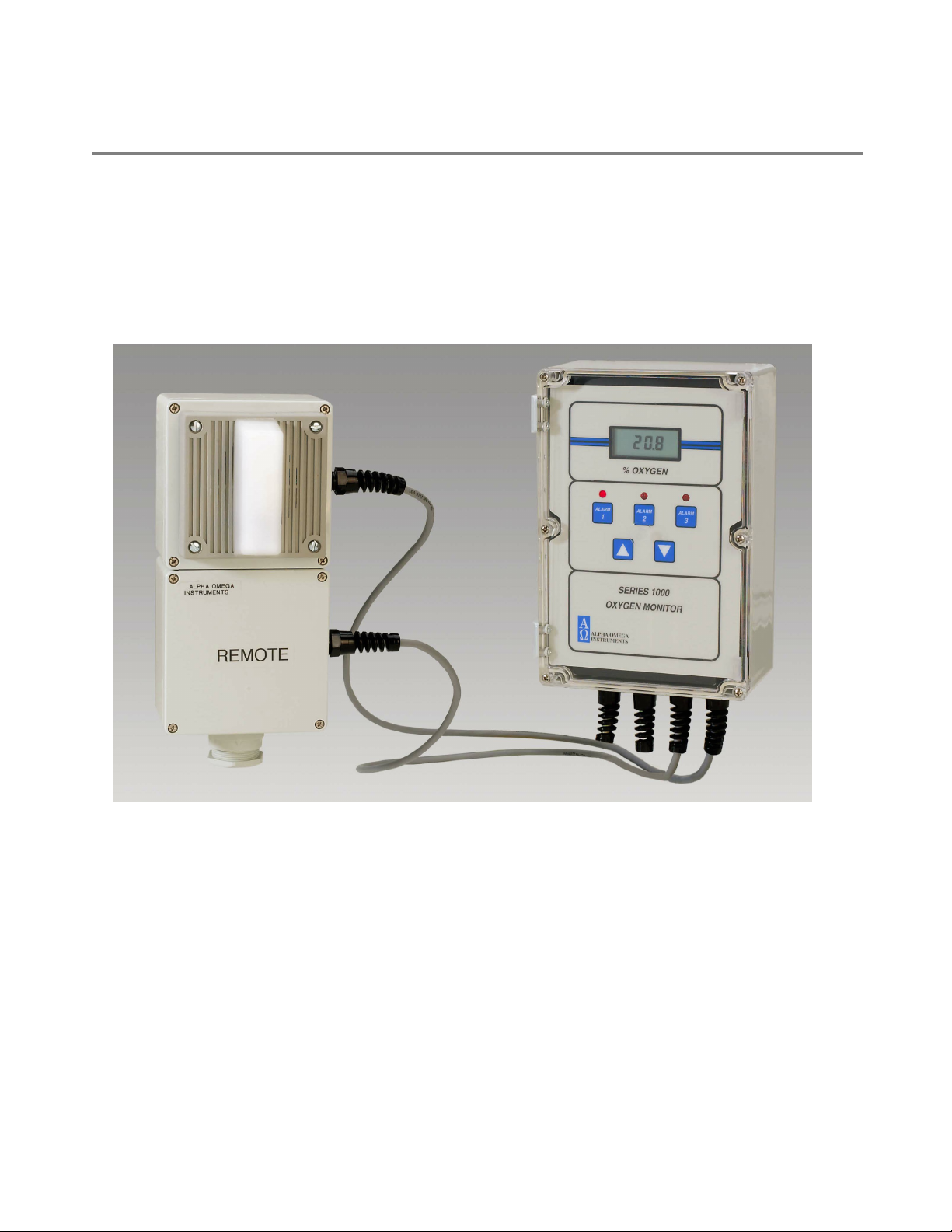
Alpha Omega Instruments
12 Optional 115 VAC Horn/Strobe Alarm
The following sections describe how to wire an an optional 115 VAC powered Horn & Strobe Alarm
Annunciator (P/N HnSt-115).
The Horn/Strobe alarm can be mounted with the Series 1000 electronics or in a remote location with
or without a remote sensor. Please review details of purchase order to determine the exact
configuration of your system.
Figure 12-1: Optional AC Powered Horn and Strobe
12.1 Installation and Wiring
The Horn & Strobe Alarm Annunciator chassis is shipped pre-wired to its companion Series 1000
Oxygen Deficiency Monitor with a length (stated in purchase order) of shielded instrumentation wire.
This section provides instructions for wiring.
Remove 110 VAC power from the Series 1000 Monitor prior to the opening of either the Series
1000 chassis or the Horn & Strobe Alarm Annunciator Chassis.
Series 1000 Oxygen Deficiency Monitor Page 48

Alpha Omega Instruments
12.1.1 Installation
After mounting the Horn & Strobe Alarm Annunciator chassis in the desired location, wire it to the
Series 1000 Oxygen Deficiency Monitor. Figure 12-2 provides wiring information.
Make wiring connections to the three position terminal block located on the inside of the monitor
enclosure.
REMOVE AC POWER FROM THE MAIN CHASSIS OF THE Series 1000 Oxygen Deficiency
Monitor BEFORE WIRING.
To connect the Horn/Strobe Alarm:
1. Remove the power from the monitor by removing the AC power at the source supply.
2. Loosen the six screws that hold the clear cover in place, and lift the clear cover away. You will
be able to lift and rotate the monitor front panel, exposing the inside rear surface of the case
where the barrier strip is located.
3. The Horn & Strobe Alarm Annunciator wires pass through a cable strain relief.
4. Once the Monitor wires are terminated, the wire can be run to the location of the Horn & Strobe
Alarm Annunciator and terminated there.
5. Remove the Horn & Strobe Alarm Annunciator cover by removing the four screws and lifting
the cover off the conduit box. I
6. Insert the Instrumentation wire into one of the conduit entry holes and terminate the wires as
shown in Figure 12-2
7. Restore 110 VAC power back to the Series 1000 Monitor only after the Horn & Strobe Alarm
Annunciator Chassis is closed by replacing the cover assembly.
8. Connect the Ground wire to the conduit box.
NOTE: The Horn & Strobe Alarm Annunciator will activate when Oxygen Alarms A1 OR A2 are
active. Oxygen Alarm 3 or System Alarm #4 are reserved for connection to a local control
system, and will not cause the annunciator to activate.
Series 1000 Oxygen Deficiency Monitor Page 49

Alpha Omega Instruments
Figure 12-2: AC Powered Horn and Strobe
Series 1000 Oxygen Deficiency Monitor Page 50

Alpha Omega Instruments
12.2 Setting the dBA Sound Level
To set the sound level:
1. Locate the four position DIP switch on the alarm module. DIP switch position 1 of this switch
sets the dBA level of the audio alert.
• To set HIGH decibel levels of (approximately 85dB) set DIP Switch Position 1 to ON
• To set STANDARD decibel levels (approximately 3-4 dB less than HIGH levels). The unit is
shipped with the switch in the OFF position.
Figure 12-3: Decibel Level Sound Output Settings
Multi-tone strobe signals at close range (fifteen inches or less) can produce a sound pressure
level that exceeds the maximum safe decibel level permitted by ADA and OSHA rules.
Exposure to these sound pressure levels can damage hearing. Do NOT operate the unit within
fifteen (15) inches of your ear, and take appropriate precautions when mounting and
connecting the unit.
12.3 Selecting the Sound Pattern for the Audible Signal
Eight (8) sound patterns are available from the audible indicator, determined by the settings of
Positions 2-4 of SW1. The following table shows the settings for the available sound patterns. It is not
recommended that either “Code 3” setting (horn or tone) be selected for any other use than Fire
Evacuation.
Table 12-1: Alarm Tone Settings
Series 1000 Oxygen Deficiency Monitor Page 51

Alpha Omega Instruments
13 Appendix A - ISEN Oxygen Sensor – Material Safety
Data Sheet
SECTION I - PRODUCT IDENTIFICATION
Alpha Omega Instruments Corp
Address
Telephone
Date Prepared
Date Revised
Trade Name
Description
SECTION II - HAZARDOUS INGREDIENTS OF SOLUTION
Lead Acetate, Trihydrate CAS # 6080-56-4
TLV and PEL are for lead, inorganic dusts and fumes, as Pb
Note: Lead has been reported as causing cancer in laboratory animals, exercise due care.
30 Martin Street
401-333-8580
September 3, 1998
April 12, 2001
2SEN and 1SEN
Weak acidic solution encapsulated in plastic housing.
OSHA/PEL 0.05 mg/m3
ACGIH/TLV 0.15 mg/m3
Acetic Acid, Glacial CAS # 64-19-7
OSHA/PEL 10 PPM
ACGIH/TLV 10 PPM
NOTE: TLV and PEL are for concentrated (90% - 100%) Acidic Acid, actual solution is less than 50%.
Lead
CAS # 7439-92-1
OSHA/PEL 0.03mg/m3
SECTION III - PHYSICAL & CHEMICAL CHARACTERISTICS
Boiling Point: Not Available Specific Gravity: Not Available
Vapor Pressure: Not Available Vapor Density: Not Available
Evaporation Rate: Not Available Physical State: Liquid
Melting Point: Not Available pH: 3.5 - 7.0 Flash Point: > 100 degrees C
Appearance & Odor: Colorless Liquid: Vinegar like odor
Extinguisher Media: Use water spray, alcohol foam, dry chemical or carbon dioxide
Special Fire Fighting Procedures: Respiratory protection should be used to avoid breathing fumes.
Unusual Fire & Explosion Hazards:
Lead acetate decomposes at boiling point and toxic gases are produced. Acetic acid vapors
may flow along surfaces to distant ignition sources and flash back. Closed containers exposed
to heat may explode.
Series 1000 Oxygen Deficiency Monitor Page 52

Alpha Omega Instruments
SECTION IV - REACTIVITY DATA OF SOLUTION
Stability
Stable
Hazardous Polymerization:
Conditions to Avoid:
Incompatibles:
Decomposition Products:
Will not occur
Heat, flame, other sources of ignition
Strong acids, strong bases, strong oxidizing agents.
Lead fumes, carbon monoxide, carbon dioxide.
SECTION V - HEALTH HAZARD DATA OF SOLUTION
Lead Acetate Component Data is for lead, inorganic dusts and fumes as Pb
(TLV/TWA):
STEL:
PEL:
Toxicity:
Carcinogenicity:
0.15 mg/m3
Not Established
0.05 mg/m3
Intraperitioneal Rate LD50 for Lead Acetate
Trihydrate is 200 mg/Kg
This substance is listed as a NTP anticipated human carcinogen
and an IARC animal carcinogen.
Reproductive Effects:
Effects of Overexposure:
INHALATION:
SKIN CONTACT:
EYE CONTACT:
SKIN ABSORPTION:
INGESTION:
None identified
Tightness and pain in chest, coughing, difficult breathing.
Irritation.
Irritation.
May be harmful.
Is harmful and may be fatal, headache, nausea, vomiting,
dizziness, gastrointestinal irritation.
CHRONIC EFFECTS:
Anemia, kidney damage, blurred vision, lead build-up in the
central nervous system.
Target Organs:
Medical Conditions Generally
Aggravated by Exposure:
Primary Routes of Entry:
GI tract, central nervous system, kidneys, blood, gingival tissue.
None identified.
Ingestion, inhalation, eye contact, skin contact, absorption.
Series 1000 Oxygen Deficiency Monitor Page 53

Alpha Omega Instruments
Emergency and First Aid Procedures:
INGESTION:
INHALATION:
SKIN CONTACT:
EYE CONTACT:
CALL A PHYSICIAN. Give large amounts of water.
If inhaled, remove to fresh air.
In case of contact, flush with water for at least 15 minutes.
In case of contact, flush with water for at least 15 minutes.
SECTION V - HEALTH HAZARD DATA OF SOLUTION continued
Acetic Acid Data is for concentrated acid.
Threshold Limit value (TLV/TWA)
Short term exposure limit (STEL)
Permissible exposure limit (PEL)
Toxicity:
Oral rate LD50 for acetic acid:
Intravenous mouse LD50 for acetic acid:
Skin rabbit LD50 for acetic acid:
Inhalation mouse LD50 for acetic acid:
Carcinogenicity NTP:
IARC
Z List:
OSHA Reg:
25 mg/m3
37 mg/m3
25 mg/m3
3310 mg/kg
525 mg/kg
1060 mg/kg
5620 mg/kg
No
No
No
No
Carcinogenicity:
Reproductive Effects:
Effects of Overexposure:
INHALATION:
SKIN CONTACT:
EYE CONTACT:
SKIN ABSORPTION:
INGESTION:
None identified
None identified
Severe irritation or burns of respiratory system
Severe burns, may cause dermatitis
Severe burns, permanent eye damage.
None identified
Burns to mouth and throat, nausea, vomiting, gastrointestinal
irritation, diarrhea, shock, may be fatal
CHRONIC EFFECTS:
Target Organs:
Medical Conditions Generally
Lung damage, teeth damage
Respiratory system, eyes, skin, teeth, lungs.
Respiratory system disease, skin disorders.
Series 1000 Oxygen Deficiency Monitor Page 54

Alpha Omega Instruments
Aggravated by Exposure:
Primary Routes of Entry:
Emergency and First Aid Procedures:
INGESTION:
INHALATION:
SKIN CONTACT:
EYE CONTACT:
Inhalation, ingestion, skin contact, eye contact.
CALL A PHYSICIAN. Give large amounts of water.
If inhaled, remove to fresh air.
Immediately flush skin with plenty of water for at least 15 minutes.
Immediately flush with plenty of water for at least 15 minutes.
SECTION VI - SPILL AND DISPOSAL PROCEDURES
NOTE: The sensors are sealed, and under normal circumstances, the contents of the
sensors do not present a health hazard. The following information is given as a guide in the
event that a cell leaks.
Steps to be taken in the event of a spill or discharge:
Wear respiratory protection and full protective clothing
Neutralize spill with soda ash or lime
Carefully place material into clean, dry container and cover.
Flush spill area with water.
Disposal Procedure:
Dispose in accordance with all applicable federal, state and local environmental regulations, with regards to lead or lead
acetate.
EPA Hazardous Waste Numbers:
Lead
Lead Acetate
D008
U144 (Toxic Waste)
Acetic Acid, Glacial D001, D002 (Ignitable, Waste)
Series 1000 Oxygen Deficiency Monitor Page 55

Alpha Omega Instruments
SECTION VII - ENGINEERING AND WORK PRACTICES CONTROLS
VENTILATION: Use general or local exhaust ventilation to meet TLV requirements.
RESPIRATORY PROTECTION: Respiratory protection required if airborne concentration exceeds
TLV.
EYE/SKIN PROTECTION: Safety goggles, uniform, apron, neoprene gloves are recommended.
Protective measures during cell replacement:
Before opening the packaging containing the sensor cell, check the sensor cell for leakage. If the sensor cell
leaks, do not open the container. If there is liquid around the cell while in the instrument, use the protection
listed above in this section.
SECTION VIII – STORAGE AND HANDLING PRECAUTIONS
Store in a cool, well-ventilated area.
Note:
The above data is based on tests and experience which Alpha Omega Instruments, Inc. believes reliable and
supplied for information purposes only. Alpha Omega Instruments Corp. disclaims any liability for damage or
injury which results from the use of the data and nothing contained therein shall constitute a guarantee,
warranty (including warranty of merchantability) or representation (including freedom from patent liability) by
Alpha Omega Instruments Corp. with respect to the data, the product described, or their use for any specific
purpose, even if that purpose is known to Alpha Omega Instruments Corp.
Series 1000 Oxygen Deficiency Monitor Page 56

Alpha Omega Instruments
14 Appendix B - Nickle Hydride Battery Material Safety
Data Sheet
Date: 27 MAY, 2003
Identity (As Used on Label and List) Note: Blank spaces are not permitted if any item is not applicable or no
GP160AAH information is available, the space must be marked to indicate that.
Section I
Manufacturer's Name Emergency Telephone Number
GPI International Ltd. / GP Batteries (U.S.A.) Inc.
Address (Number, Street, City, State, and ZIP Code) Telephone Number for information
8/F, Gold Peak Building, 30 Kwai Wing Road, Kwai Chung, N.T. Hong Kong (852) 2484 3333
11235 West Bernardo Court, San Diego, CA92127-1638, U.S.A. (619) 674 5620
Section II - Hazardous Ingredients/Identity Information
Hazardous Components:
Description: Approximate % of total weight
Ni(OH)2 (Nickel Hydroxide) ; 25 Wt%
30%KOH Solution (Potassium Hydroxide) ; 10 Wt%
Mercury ; <5 ppm
Lead ; Nil
Cadmium ; Nil
Section III - Physical/Chemical Characteristics
Boiling point Specific Gravity (H2O=1)
N.A. N.A.
Vapor Pressure (mm Hg) Melting Point
N.A. N.A
Vapor Density (AIR =1) Evaporation Rate
N.A. (Butyl Acetate =1) N.A.
Solubility in Water
N.A.
Appearance and Odor
Cylindrical Shape, odorless
Section IV - Fire and Explosion Hazard Data
Flash Point (Method Used) Flammable Limits LEL UEL
N.A. N.A. N.A. N.A.
Extinguishing Media
N.A.
Special Fire Fighting Procedures
N.A.
Unusual Fire and Explosion Hazards
When exposed to excess heat, cell may burst
Section V - Reactivity Data
Stability: Unstable Conditions to Avoid
Incompatibility (Materials to Avoid)
Stable X
Series 1000 Oxygen Deficiency Monitor Page 57

Alpha Omega Instruments
Hazardous Decomposition or Byproducts
When heated, battery may emit hazardous vapors of KOH/NaOH & Hg.
Hazardous reactions: May Occur Conditions to Avoid Will Not Occur X
Section VI - Health Hazard Data
Route(s) of Entry Inhalation? Skin? Ingestion?
Health Hazard (Acute and Chronic)
N.A.
N.A. N.A. N.A.
Carcinogenicity NTP? LARC Monographs? OSHA Regulated?
Signs and Symptoms of Exposure
In case of electrolyte leakage, skin will be itchy when contaminated by electrolyte.
Medical Conditions
Generally Aggravated by Exposure N.A.
Emergency and First Aid Procedures
In the event that electrolytes gets on skin, wash immediately with water. For eye contact, flush with copious amounts of water for 15 minutes
and see physician..
N.A. N.A. N.A.
Section VII - Precautions for Safe Handling and Use
Steps to Be Taken in Case Material is Released or Spilled
Use neoprene, rubber latex-nitrile gloves when handling leakers. If liquid from leaker comes in contact with skin, wash immediately with
water. For eye contact, flush with copious amounts of water for 15 minutes and see physician.
Waste Disposal Method
Do not incinerate. Battery may explode.
Precaution to Be Taken in Handling and Storing
The battery is extremely sensitive to adverse effect of humidity. Be sure to store them in a place which is dry and subject to little temperature
change. Do not place near the boiler or radiator, nor expose to the direct sunlight. Do not dispose of the battery in fire. Do not charge the battery.
Do not short-circuit the battery. Do not put in backward position. Do not disassemble the battery, handling in such manner can cause the battery
to explode, leak and injury.
Other Precautions
Install batteries in accordance with equipment instructions. Replace all batteries in equipment at the same time. Do not mix battery systems of
different types. Do not carry batteries loose in your pocket or carrying bag. Check batteries periodically when in use.
Section VIII - Control Measures
Respiratory Protection (Specify Type)
Ventilation Local Exhausts Special
Protective Gloves Eye Protection
N.A. N.A.
Other Protective Clothing or Equipment
N.A.
Work/Hygienic Practices
N.A.
Series 1000 Oxygen Deficiency Monitor Page 58
N.A. N.A.
Mechanical (General) Other
N.A. N.A.

Alpha Omega Instruments
15 Appendix C-Effects of Different Oxygen Levels on
Humans
The following is a list of different oxygen levels along with the corresponding effects it has on normal
life.
1. 23.5% is the maximum safe concentration established by the Occupational Health & Safety
Administration (OSHA).
2. 20.9% is the normal oxygen concentration at sea level.
3. 19.5% oxygen is the minimum safe concentration established by OSHA.
4. At approximately 19.0% oxygen, there may be some impairment to judgement but it may be
hardly noticeable.
5. At approximately 16.0%-19% oxygen, hypoxic conditions will likely be experienced where the
body is deprived of an adequate oxygen supply and there may be some impairment to
judgement.
6. At between approximately 13%-16% oxygen, breathing becomes rapid as does the person's
pulse rate. The individual will become emotionally upset.
7. At between approximately 10%-13% oxygen, a strong feeling of fatigue takes over with
strained respiration. There is a distinct possibility that the person will be rendered unconscious
without forewarning.
8. Below 10%, there is an increased inability to move with fainting almost immediately upon
exposure to the oxygen deficient atmosphere. Convulsions and death will follow as the oxygen
levels approach approximately 7%.
Series 1000 Oxygen Deficiency Monitor Page 59
 Loading...