

Page 1

Product External Specifications
For
802.11b/g/n 2x2 USB Module
(MTK RT5372)
Customer : TPV
Model P/N
TPV : 317GAAWF506ALP
Alpha : TPWUSN24V2A1G
Model Number: WUS-N24V2
Version : 1.3
Alpha Networks Proprietary and Confidential Information
1
Page 2

Revision History
Rev. Date Author Reason for Changes
1.0 2013/07/01 Yu-Chun Yu
1.1 2013/08/06 Doreen Chang
1.2 2013/8/19 Doreen Chang
1.3 2014/08/01 Doreen Chang
•
Draft Release
•
Add packing and the photo of module
•
Add model number in cover page
•
Add FCC ID information
Alpha Networks Proprietary and Confidential Information
2
Page 3

Contents
OPERATION MANUAL ....................................................................................................................................................... 4
1.0 SCOPE ............................................................................................................................................................................... 5
OCUMENT
1.1 D
1.2 P
RODUCT FEATURES
.................................................................................................................................................................... 5
...................................................................................................................................................... 5
2.0 REQUIREMENTS ............................................................................................................................................................ 6
UNCTIONAL BLOCK DIAGRAM
2.1 F
ENERAL REQUIREMENTS
2.2 G
..................................................................................................................................... 7
............................................................................................................................................. 7
2.2.1 IEEE 802.11b Section ............................................................................................................................................ 7
2.2.2 IEEE 802.11g Section ............................................................................................................................................ 8
2.2.3 IEEE 802.11n Section ............................................................................................................................................ 8
2.2.4 General Section ..................................................................................................................................................... 9
2.3 S
OFTWARE REQUIREMENTS
......................................................................................................................................... 10
2.3.1 Information .......................................................................................................................................................... 10
2.3.2 Configuration....................................................................................................................................................... 10
2.3.3 Security ................................................................................................................................................................ 10
2.4 M
ECHANICAL REQUIREMENTS
2.5 C
OMPATIBILITY REQUIREMENTS
2.6 R
EQUIREMENTS OF RELIABILITY
..................................................................................................................................... 11
................................................................................................................................. 11
, M
AINTAINABILITY AND QUALITY
........................................................................... 11
2.7 E
NVIRONMENTAL REQUIREMENTS
2.8
FCC ID……………………………………………………………………………………………………………………………………………
............................................................................................................................... 12
Alpha Networks Proprietary and Confidential Information
3
12
Page 4
Operation Manual
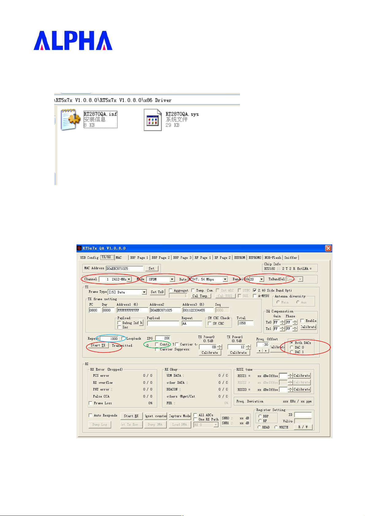
i. Install Driver
1. install the test driver
2. TX signal command
˄1˅ select TX/RX site
˄2˅ select channel,datarate,bandwidth and chain0/1
˄3˅ for continue TX select conti,press start tx;for continue packets tx,set repeat to 0,press start tx
Alpha Networks Proprietary and Confidential Information
4
Page 5
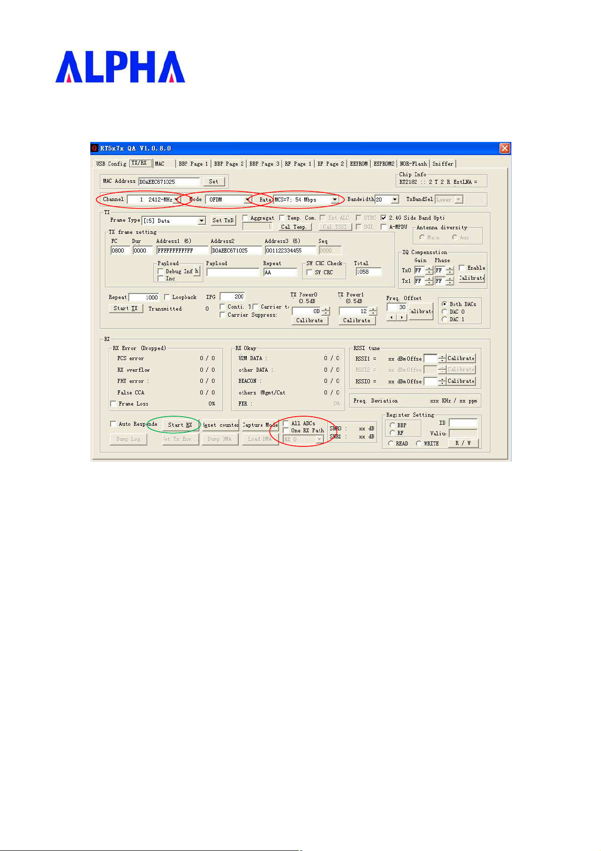
3. RX signal command
(1) select TX/RX site
(2) select channel,datarate and chain 0/1
1.1 Scope
1.2 Document
This document is to specify the product requirements for 802.11n USB Module with onboard m etal an t en na . This USB
module is based on MTK Ralink single chip that complied with 802.11n standard from 2.4~2.5GHz, and it can be used to
provide up to 11Mbps for IEEE 802.11b, 54Mbps for IEEE 802.11g and 300Mbps for 802.11n to connect your wireless
LAN.
With seamless roaming, fully interoperability and advanced security with WEP standard, 802.11n USB Module offers
absolute interoperability with different vendors’ 802.11b, 802.11g, and 802.11n Access Points through the wireless LAN.
1.3 Product Features
•
Compatible with IEEE 802.11g standard to provide wireless 54Mbps data rate
•
Compatible with IEEE 802.11b standard to provide wireless 11Mbps data rate
•
Compatible with IEEE 802.11n standard to provide wireless 300Mbps data rate
Alpha Networks Proprietary and Confidential Information
5
Page 6

•
Supports infrastructure networks via Access Point and ad-hoc network via peer-to-peer communication
•
Supports WEP, 802 .1x, WPA and WPA2 enhan c e d secu ri ty
•
Friendly user configuration and diagnostic utilities
•
Drivers support Windows XP , Vista, Win7 .
•
6-pin pitch connector USB interface
•
RoHS compliant
•
Antenna type : Two onboard metal Antenna
2.0 Requirements
The following sections identify the detailed requirements of 802.11b/g/n embedded USB Module
Alpha Networks Proprietary and Confidential Information
6
Page 7

2.1 Functional Block Diagram
2.2 General Requirements
2.2.1 IEEE 802.11b Section
# Feature Detailed Description
•
2.2.1.1 Standard
2.2.1.2 Radio and
Modulation
Schemes
2.2.1.3 Operating
Frequency
2.2.1.4 Channel Numbers
2.2.1.5 Data Rate
2.2.1.6 Media Access
Protocol
2.2.1.7 Transmitter Output
Power
2.2.1.8 Receiver Sensitivity
2.2.1.9 Receiver Maximum
Input Level
IEEE 802.11b
•
DQPSK, DBPSK, DSSS, and CCK
•
2400 ~ 2483.5MHz ISM ban d
•
11 channels for United States
13 channels for Europe Countries and other regions
•
11, 5.5, 2, and 1Mbps
•
CSMA/CA with ACK
•
Typical RF Output Power at each RF chain, Data Rate and at room
Temp. 25degree C
•
16 dBm(Ʋġ2dB) at 1,2,5.5,11Mbps
•
Typical Sensitivity at each RF chain. Frame (1000-byte PDUs) Error
Rate = 8%
•
-76 dBm at 1Mbps
•
-76 dBm at 2Mbps
•
-76 dBm at 5.5Mbps
•
-76 dBm at 11Mbps
The Receiver shall provide a maximum PER of 8 % at a PSDU length of
1000 bytes for a maximum input level of -10 dBm measured at each antenna
for any baseband modulation
Alpha Networks Proprietary and Confidential Information
7
Page 8

2.2.2 IEEE 802.11g Section
# Feature Detailed Description
•
2.2.2.1 Standard
2.2.2.2 Radio and
Modulation
Schemes
2.2.2.3 Operating
Frequency
2.2.2.4 Channel Numbers
2.2.2.5 Data Rate
2.2.2.6 Media Access
Protocol
2.2.2.7 Transmitter Output
Power
2.2.2.8 Receiver Sensitivity
2.2.2.9 Receiver Maximum
Input Level
IEEE 802.11g
•
BPSK, QPSK, 16QAM, 64QAM, and OFDM
•
2400 ~ 2483.5MHz ISM ban d
•
11 channels for United States
13 channels for Europe Countries and other regions
•
6,9,12,18,24,36,48,54Mbps
•
CSMA/CA with ACK
•
Typical RF Output Power at each RF chain, Data Rate and at room
Temp. 25degree C
•
16Ʋġ2dBm at 6,9 Mbps
•
15Ʋġ2dBm at 12,18 Mbps
•
15Ʋġ2dBm at 24,36 Mbps
•
14Ʋġ2dBm at 48,54 Mbps
•
Typical Sensitivity at each RF chain. Frame (1000-byte PDUs) Error
Rate = 8%
•
-82 dBm at 6Mbps
•
-81 dBm at 9Mbps
•
-79 dBm at 12Mbps
•
-77 dBm at 18Mbps
•
-74 dBm at 24Mbps
•
-70dBm at 36Mbps
•
-66dBm at 48Mbps
•
-65 dBm at 54Mbps
The Receiver shall provide a maximum PER of 10 % at a PSDU length of
1000 bytes for a maximum input level of -20 dBm measured at each antenna
for any baseband modulation
2.2.3 IEEE 802.11n Section
# Feature Detailed Description
2.2.3.1 Standard
2.2.3.2 Radio and
Modulation Type
2.2.3.3 Operating
Frequency
2.2.3.4 Data Rate
Alpha Networks Proprietary and Confidential Information
•
IEEE 802.11n
•
BPSK, QPSK, 16QAM, 64QAM with OFDM
•
2400 ~ 2483.5MHz ISM ban d
GI=800ns GI=400ns
MCS
0 6.5 13.5 7.2 15
1 13 27 14.4 30
2 19.5 40.5 21.7 45
3 26 54 28.9 60
4 39 81 43.3 90
5 52 108 57.8 120
6 58.5 121.5 65.0 135
7 65 135 72.2 150
20MHz 40MHz 20MHz 40MHz
8
Page 9

# Feature Detailed Description
15130270144.4443
00
2.2.3.5 Media Access
Protocol
2.2.3.6 Transmitter Output
Power at Antenna
Connector
8 13 27 14.444 30
9 26 54 28.889 60
10 39 81 43.333 90
11 52 108 57.778 120
12 78 162 86.667 180
13 104 216 115.556 240
14 117 243 130.000 170
•
CSMA/CA with ACK
•
Typical RF Output Power at each RF chain, Data Rate and at room
Temp. 25degree C
•
2.4GHz Band/HT-20
•
13Ʋġ2dBm at MCS0/1
•
13Ʋġ2dBm at MCS2/3
•
13Ʋġ2dBm at MCS4/5
•
13Ʋġ2dBm at MCS6/7
•
2.4GHz Band/HT-40
•
13Ʋġ2dBm at MCS0/1
•
13Ʋġ2dBm at MCS2/3
•
13Ʋġ2dBm at MCS4/5
•
13Ʋġ2dBm at MCS6/7
2.2.3.7 Receiver Sensitivity
at Antenna
Connector
2.2.3.8 Receiver Maximum
Input Level
•
Typical Sensitivity at each RF chain. Frame (4096 octets PSDUs).
Error Rate <10% and at room Temp. 25degree C
•
HT-20
•
-80 dBm at MCS 0/8
•
-77 dBm at MCS 1/9
•
-75 dBm at MCS 2/10
•
-72 dBm at MCS 3/11
•
-68 dBm at MCS 4/12
•
-64 dBm at MCS 5/13
•
-63 dBm at MCS 6/14
•
-62 dBm at MCS 7/15
•
HT-40
•
-77 dBm at MCS 0/8
•
-74 dBm at MCS 1/9
•
-72 dBm at MCS 2/10
•
-69 dBm at MCS 3/11
•
-65 dBm at MCS 4/12
•
-61 dBm at MCS 5/13
•
-60 dBm at MCS 6/14
•
-59 dBm at MCS 7/15
The Receiver shall provide a maximum PER of 10 % at a PSDU length of
1000 bytes for a maximum input level of -30 dBm measured at each antenna
for any baseband modulation
2.2.4 eneral Section
# Feature Detailed Description
2.2.4.1 Antenna Type
Alpha Networks Proprietary and Confidential Information
•
Onboard metal Antenna
9
Page 10

2.2.4.2OperatingVolt
age
•
2.2.4.4
Interface
3.3VDC +/- 10%
•
2.2.4.3 Current
Consumption
450mA at continuous transmit mode @HT40 MCS0
315mA at receive mode w/o receiving packet @HT40 MCS0
•
6-pin pinch connector , wafer
2.3 Software Requirements
The Configuration Software supports Microsoft Windows XP, Vista, Win7. This configuration software includes the
following functions:
•
Information
Information allows you to monitor network status.
•
Configuration
Configuration allows you to configure parameters for wireless networking.
•
Security
Supports enhanced security WEP, WPA and WPA2.
2.3.1 nformation
# Feature Detailed Description
2.3.1.1 General Information
2.3.1.2 Current Link
Information
2.3.1.3 Site survey
2.3.2 Configuration
# Feature Detailed Description
2.3.2.1 ESS ID
2.3.2.2 MAC
2.3.2.3 Signal
2.3.2.4 Security
2.3.2.5 Channel
2.3.3 curity
•
General Information shows the name of Wireless A dapter, Adapter
MAC Address, Regulatory Domain, Driver Version, and Utility
Version.
•
Current Link Infor mation shows the Current Setting ESSID, Channe l
Number, Associated BSSID, Network Type, Security Status, Link
Status, Signal Strength.
•
To search the neighb oring access points and display the information
of all access points.
•
Input an SSID number if the roaming feature is enabled
•
Supports for ASCII printable charac ters.
•
The MAC address of the wireless device
•
The link quality of the wireless connection
•
If there is a “lock” icon, it means the wireless network is secure.
Must know the encryption key/security settings to connect.
•
The wireless network
# Feature Detailed Description
2.3.3.1 Encryption
2.3.3.2 WEP Management
Alpha Networks Proprietary and Confidential Information
•
RC4 encryption algorithm
•
Support 64/128 bit WEP encryption
•
Support open system and shared key authentication
•
Four WEP keys can be selected
•
STA with WEP off will never associate any AP with WEP enabled
•
WEP Key Format: Option for Hex format
10
Page 11

# Feature Detailed Description
•
2.3.3.4 WPA/WPA2
Support WPA/WPA2-PSK and WPA/WPA2-EAP
•
Support Cipher Mode AES and TKIP
2.4 Mechanical Requirements
# Feature Detailed Description
2.4.1 Length
2.4.2 Width
•
100mm ± 0.005mm (PCB)
•
17mm ±0.005mm (PCB)
2.5 Compatibility Requirements
This device passes the following compatibility requirements.
# Feature Detailed Description
2.5.1 Wi-Fi
2.5.2 Physical Layer and
Functionality
•
Meet Wi-Fi certification for IEEE 802.11 product
•
Meet ALPHA Engineering Test Plan and Test Report
2.6 Requirements of Reliability, Maintainability and Quality
# Feature Detailed Description
•
2.6.1 MTBF
2.6.2 Maintainability
2.6.3 Quality
Mean Time Between Fa ilure > 30,000 hours
•
There is no scheduled preventive maintenance required
•
The product quality is followed-up by ALPHA factory quality control
system
Alpha Networks Proprietary and Confidential Information
11
Page 12

2.7 Environmental Requirements
# Feature Detailed Description
•
2.7.1 Operating
Temperature
Conditions
2.7.2 Non-Operating
Temperature
Conditions
2.7.3 Operating
Humidity
conditions
2.7.4 Non-Operating
Humidity
Conditions
The product is capab le of continuous reliable operatio n when operating
in ambient temperature of 0 ćto +50ć.
•
Neither subassemblies is damaged nor the operation al performance is
degraded when restored to the operating temperature after exposing to
storage temperature in the range of –20 ćto +75 ć.
•
The product is capable of continuous reliable operation when subjected
to relative humidity in the range of 10% and 90% non-condensing.
•
The product is not damaged nor the performance is degraded after
exposure to relative humidity r anging from 5% to 95% non-condensing
2.8 FCC ID
FCC ID: RRK-WUSN24V2
This device complies with part 15 of the FCC Rules. Operation is subject to the following two
conditions: (1) This device may not cause harmful interference, and (2) this device must accept any
interference received, including interference that may cause undesired operation.
Alpha Networks Proprietary and Confidential Information
12
Page 13

Federal Communication Commission Interference Statement
This device complies with Part 15 of the FCC Rules. Operation is subject to
the following two conditions: (1) This device may not cause harmful
interference, and (2) this device must accept any interference received,
including interference that may cause undesired operation.
This equipment has been tested and found to comply with the limits for a
Class B digital device, pursuant to Part 15 of the FCC Rules. These limits
are designed to provide reasonable protection against harmful interference in a
residential installation. This equipment generates, uses and can radiate radio
frequency energy and, if not installed and used in accordance with the
instructions, may cause harmful interference to radio communications.
However, there is no guarantee that interference will not occur in a particular
installation. If this equipment does cause harmful interference to radio or
television reception, which can be determined by turning the equipment off
and on, the user is encouraged to try to correct the interference by one of the
following measures:
- Reorient or relocate the receiving antenna.
- Increase the separation between the equipment and receiver.
- Connect the equipment into an outlet on a circuit different from that
to which the receiver is connected.
- Consult the dealer or an experienced radio/TV technician for help.
FCC Caution: Any changes or modifications not expressly approved by the
party responsible for compliance could void the user's authority to operate this
equipment.
This transmitter must not be co-located or operating in conjunction with any
other antenna or transmitter.
Radiation Exposure Statement:
This equipment complies with FCC radiation exposure limits set forth for an
uncontrolled environment. This equipment should be installed and operated
with minimum distance 20cm between the radiator & your body.
Page 14

This device is intended only for OEM integrators under the following conditions:
1) The antenna must be installed such that 20 cm is maintained between the
antenna and users, and
2) The transmitter module may not be co-located with any other transmitter
or antenna.
As long as 2 conditions above are met, further transmitter
test will not be
required. However, the OEM integrator is still responsible for testing their
end-product for any additional compliance requirements required with this
module installed
IMPORTANT NOTE: In the event that these conditions can not be met
(for
example certain laptop configurations or co-location with another transmitter),
then the FCC authorization is no longer considered valid and the FCC ID can
not be used on the final product. In these circumstances, the OEM integrator
will be responsible for re-evaluating the end product (including the transmitter)
and obtaining a separate FCC authorization.
End Product Labeling
This transmitter module is authorized only for use in device where the antenna
may be installed such that 20 cm may be maintained between the antenna and
users. The final end product must be labeled in a visible area with the
following: “Contains FCC ID: RRK-WUSN24V2. The grantee's FCC ID can
be used only when all FCC compliance requirements are met.
Manual Information To the End User
The OEM integrator has to be aware not to provide information to the end user
regarding how to install or remove this RF module in the user’s manual of the
end product which integrates this module.
The end user manual shall include all required regulatory information/warning
as show in this manual.
 Loading...