

Page 1

User Manual
For
WMP-ND03B
無線網路卡
Mini-PCI Card
Version: 1.1
2008/6/12
Company Confidential
Page 2

This document contains confidential proprietary information and is the property of
Alpha Networks Corporation. The contents of this document may not be disclosed to
unauthorized persons without the written consent of Alpha Networks Corporation.
Company Confidential
Page 3

Revision History
Rev. Date Author Reason for Changes
1.0 2008/3/14 Alfred Chin
1.1 2008/6/12 Alfred Chin
• New release
• Add band 4 (5725~5850MHz) in item 2.2.1.3
and 2.2.4.3
Company Confidential
Page 4

Contents
TEST OPERATION MANUAL.................................................................................................................5
Test Utility Installation:.........................................................................................................................5
Configuration:........................................................................................................................................6
1.0 SCOPE......................................................................................................................................................7
1.1 DOCUMENT ............................................................................................................................................7
1.2 PRODUCT FEATURES .............................................................................................................................7
2.0 REQUIREMENTS.................................................................................................................................8
2.1 GENERAL REQUIREMENTS ....................................................................................................................8
2.2.1 IEEE 802.11a Section...................................................................................................................8
2.2.2 IEEE 802.11b Section...................................................................................................................9
2.2.3 IEEE 802.11g Section...................................................................................................................9
2.2.4 IEEE 802.11 Draft n Section......................................................................................................10
2.2.5 General Section...........................................................................................................................11
2.3 COMPATIBILITY REQUIREMENTS........................................................................................................12
2.4 REGULATORY REQUIREMENTS ...........................................................................................................12
2.5 REQUIREMENTS OF RELIABILITY, MAINTAINABILITY AND QUALITY...............................................13
2.6 ENVIRONMENTAL REQUIREMENTS .....................................................................................................13
END PRODUCT LABELING ............................................................................................................................15
MANUAL INFORMATION TO THE END USER.............................................................................................15
Company Confidential
Page 5

Test Operation Manual
Test Utility Installation:
1. Unzip “ART_V0_5_b25ALL.zip” to “C:\”.
2. The utility must run on Win2000 or WinXP.
Hardware Installation:
Before insert the card, please execute the below instruction at first !!
1. Win2000 OS :
Enter in the directory : C:\ v0_5_b25ALL\art_driver\bin\2000
Execute the uninst_new_drv_2k.bat:
Execute the inst_new_drv_2k.bat :
WinXP OS :
Enter in the directory : C:\ v0_5_b25ALL\art_driver\bin\xp
Execute the uninst_new_drv_xp.bat:
Execute the inst_new_drv_xp.bat
2. Insert the card, then install the driver , the driver is located at
Win2000 OS :
C:\ v0_5_b25ALL\art_driver\bin\2000
WinXP OS :
C:\ v0_5_b25ALL\art_driver\bin\xp
Company Confidential
Page 6
Configuration:
1. Enter the DOS command mode , then change the directory to :
C:\ v0_5_b25ALL\art_driver\bin\xp
2. Input the instruction: art \id=2082
Then press enter .
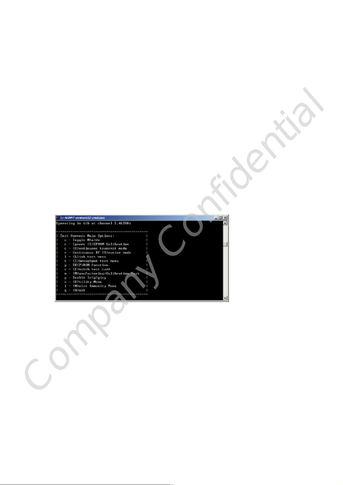
ART TEST MODE:
1. Once utility is executed, a menu with test options will appear. To run a test, press
the character key that is assigned to the test option.
For example, press “c” to run the continuous transmit test, or press “r ” to run the
continuous receive test.
For example: press “o” to change 11g or 11b test mode, Press “c” to continuous
transmit mode .
2. Continuous Transmit Options.
a. Before the Continuous Transmit test, need to press “e” first
The command will load the calibrate data to the EEROM, then the card can
transmit the target power
b. The channel frequency, data rate and output power could be changed in
continuous transmit options. Press “c” to increase the output power , 11g Power
(data rate 6Mbps) is 17dBm, 11b Power is 17dBm , Press ESC to return to the
main Test Options menu when finished.
Company Confidential
Page 7

3. Continuous Receive Options
Continuous receive options will put the radio into receive mode to allow for
radio measurements. Press ESC to return to the main Test Options menu when
finished.
1.0 Scope
1.1 Document
This document is to specify the product requirements for 802.11 a/b/g/n Mini-PCI
Card. This Card is based on Atheros chipset that complied with IEEE 802.11g, IEEE
802.11b, IEEE 802.11n standard from 2.4~2.5GHz, and it can be used to provide up to
54Mbps for IEEE 802.11g, 11Mbps for IEEE 802.11b and 300Mbps for IEEE 802.11n
to connect your wireless LAN.
With seamless roaming, fully interoperability and advanced security with WEP
standard, 802.11a/b/g/n Mini-PCI Card offers absolute interoperability with different
vendors’ 802.11g, 802.11b, 802.11 draft n Access Points through the wireless LAN.
1.2 Product Features
Ÿ Compatible with IEEE 802.11a high rate standard to provide wireless 54Mbps
data rate
Ÿ Compatible with IEEE 802.11g high rate standard to provide wireless 54Mbps
data rate
Ÿ Compatible with IEEE 802.11b high rate standard to provide wireless 11Mbps
Company Confidential
Page 8
data rate
Ÿ Compatible with IEEE 802.11 draft n standard to provide wireless 300Mbps data
rate
Ÿ Maximum reliability, throughput and connectivity with automatic data rate
switching
Ÿ Supports infrastructure networks via Access Point and ad-hoc network via
peer-to-peer communication
2.0 Requirements
The following sections identify the detailed requirements of the 802.11n/ a or g/b
Mini-PCI Card.
2.1 General Requirements
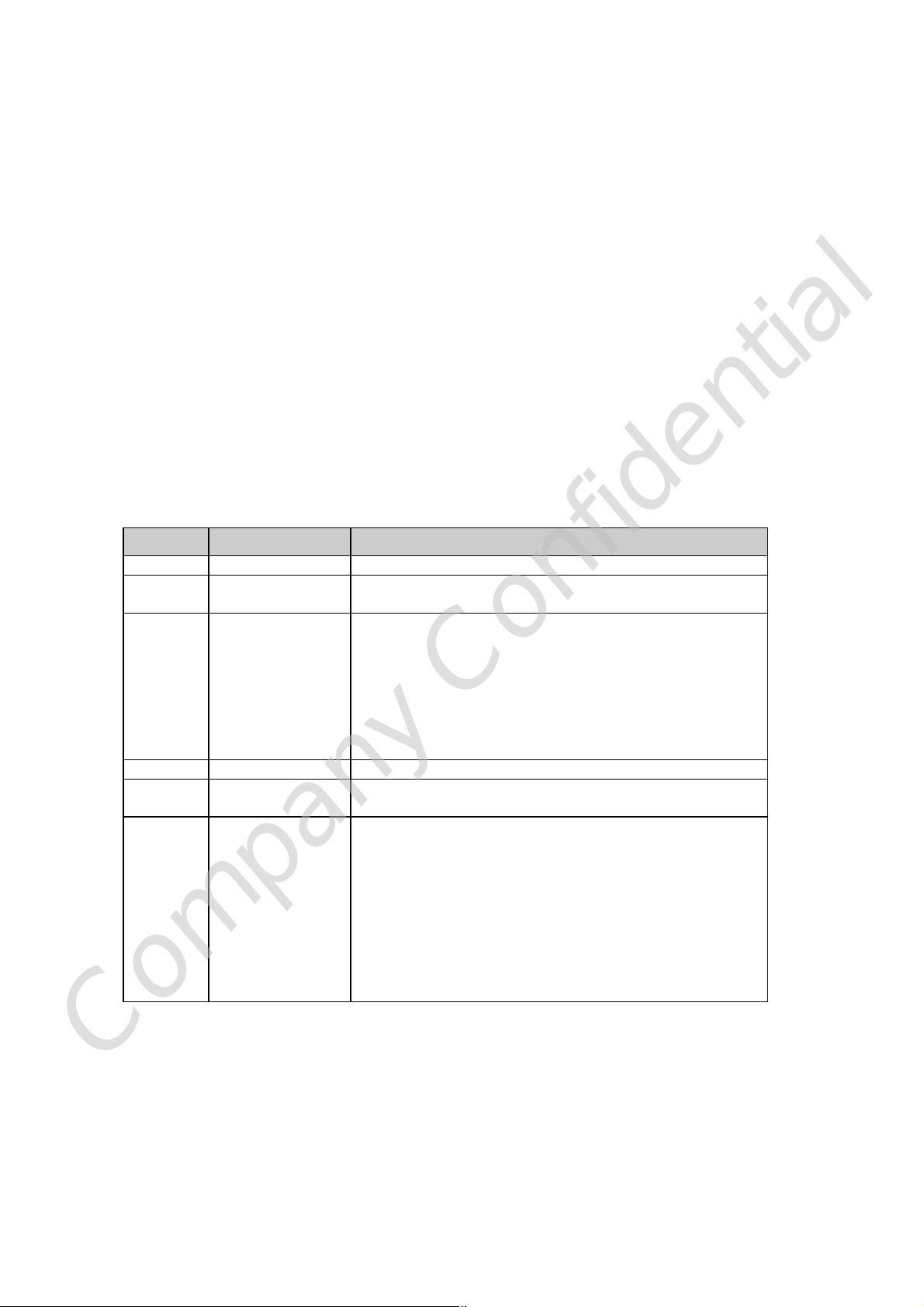
2.2.1 IEEE 802.11a Section
# Feature Detailed Description
2.2.1.1 Standard
2.2.1.2 Radio and
Modulation Type
2.2.1.3 Operating
Frequency
2.2.1.4 Data Rate
2.2.1.5 Media Access
Protocol
2.2.1.6 Receiver
Sensitivity at
Antenna Connector
IEEE 802.11a
Ÿ
BPSK, QPSK, 16QAM, 64QAM with OFDM
Ÿ
CE: 5150~5350MHz, 5470MHz ~5725MHz
C-Tick: 5150~5350MHz, 5470MHz ~5725MHz, 5725MHz
~5850MHz
FCC: 5150~5250MHz, 5725MHz ~5850MHz
IC: 5150~5250MHz, 5725MHz ~5850MHz
Taiwan NCC: 5250~5350MHz, 5725MHz ~5850MHz
Japan TELEC: 5150~5350, 5470~5725MHz
54, 48, 36, 24, 18, 12, 9 and 6Mbps
Ÿ
CSMA/CA with ACK
Typical Sensitivity at Which Frame (1000-byte PDUs)
Ÿ
Error Rate = 10% and at room Temp. 25degree C
–85dBm at 6Mbps
Ÿ
–85dBm at 9Mbps
Ÿ
–85dBm at 12Mbps
Ÿ
Ÿ –85dBm at 18Mbps
Ÿ –80dBm at 24Mbps
–78dBm at 36Mbps
Ÿ
Ÿ –74dBm at 48Mbps
Ÿ –73dBm at 54Mbps
Company Confidential
Page 9
2.2.2 IEEE 802.11b Section
# Feature Detailed Description
2.2.2.1 Standard
2.2.2.2 Radio and
Modulation
Schemes
2.2.2.3 Operating
Frequency
2.2.2.4 Channel
Numbers
2.2.2.5 Data Rate
2.2.2.6 Media Access
Protocol
2.2.2.7 Receiver
Sensitivity at
Antenna
Connector
IEEE 802.11b
Ÿ
DQPSK, DBPSK, DSSS, and CCK
Ÿ
2400 ~ 2483.5MHz ISM band
Ÿ
Ÿ 11 channels for United States/ Canada/ Taiwan
13 channels for Europe Countries/ Japan
11, 5.5, 2, and 1Mbps
Ÿ
CSMA/CA with ACK
Ÿ
Typical Sensitivity at Which Frame (1000-byte PDUs)
Ÿ
Error Rate = 8% and at room Temp. 25degree C
–92dBm at 1Mbps
Ÿ
–91dBm at 2Mbps
Ÿ
–90dBm at 5.5Mbps
Ÿ
–88dBm at 11Mbps
Ÿ
2.2.3 IEEE 802.11g Section
# Feature Detailed Description
2.2.3.1 Standard
2.2.3.2 Radio and
Modulation
Type
2.2.3.3 Operating
Frequency
2.2.3.4 Channel
Numbers
2.2.3.5 Data Rate 6,9,12,18,24,36,48,54Mbps
2.2.3.6 Media Access
Protocol
2.2.3.7 Receiver
Sensitivity at
Antenna
Connector
IEEE 802.11g
Ÿ
BPSK, QPSK, 16QAM, 64QAM with OFDM
Ÿ
2400 ~ 2483.5MHz ISM band
Ÿ
11 channels for United States/ Canada/ Taiwan
Ÿ
13 channels for Europe Countries/ Japan
CSMA/CA with ACK
Typical Sensitivity at Which Frame (1000-byte
Ÿ
PDUs) Error Rate = 10% and at room Temp.
25degree C
–87dBm at 6Mbps
Ÿ
Ÿ –87dBm at 9Mbps
Ÿ –87dBm at 12Mbps
–87dBm at 18Mbps
Ÿ
–81dBm at 24Mbps
Ÿ
–79dBm at 36Mbps
Ÿ
–75dBm at 48Mbps
Ÿ
–74dBm at 54Mbps
Ÿ
Company Confidential
Page 10

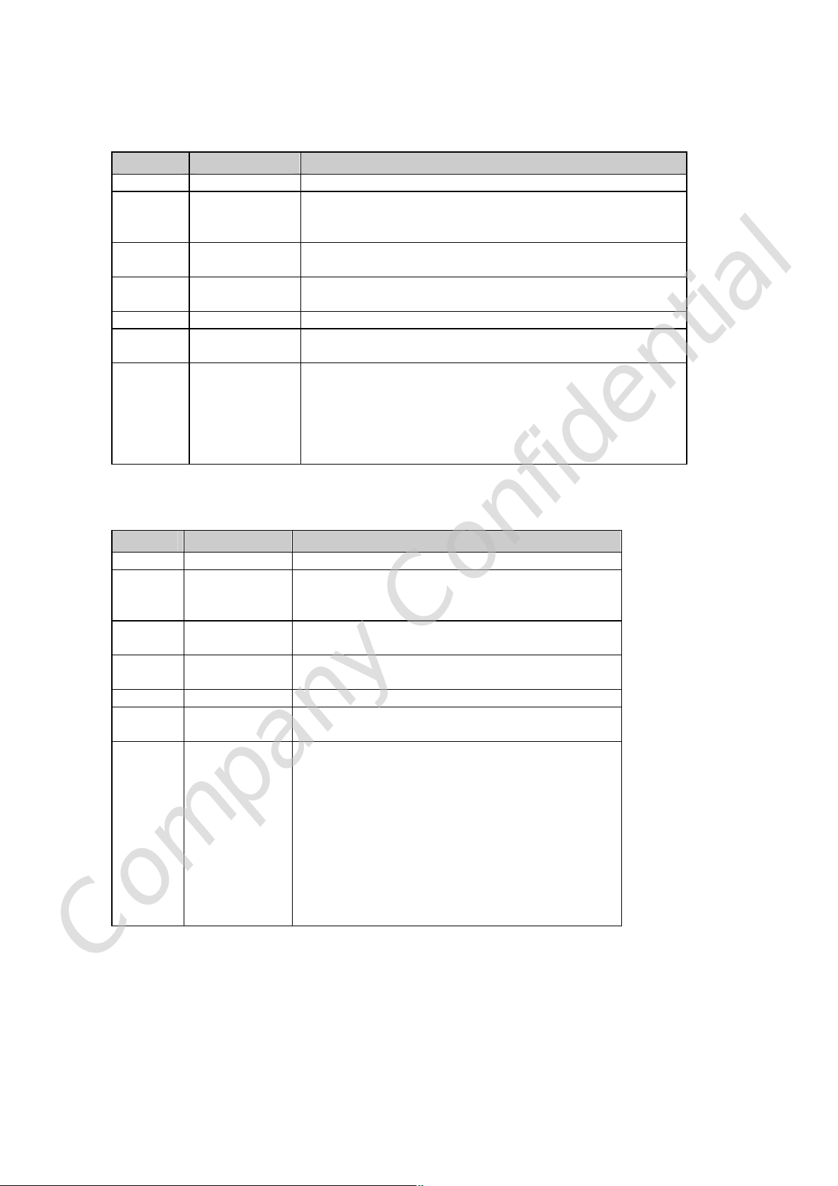
2.2.4 IEEE 802.11 Draft n Section
# Feature Detailed Description
2.2.4.1 Standard
2.2.4.2 Radio and
Modulation
Type
2.2.4.3 Operating
Frequency
2.2.4.4 Data Rate
Draft n
Ÿ
BPSK, QPSK, 16QAM, 64QAM with OFDM
Ÿ
n CE: 240 ~2483.5MHz , 5150~5350MHz,
5470MHz ~5725MHz
n C-Tick: 2400~2483.5MHz , 5150~5350MHz,
5470MHz ~5725MHz, 5725MHz ~5850MHz
n FCC: 2400~2483.5MHz , 5150~5250MHz,
5725MHz ~5850MHz
n IC: 2400~2483.5MHz , 5150~5250MHz,
5725MHz ~5850MHz
Taiwan NCC:
n
5250~5350MHz, 5725MHz ~5850MHz
Japan TELEC:
n
5470~5725MHz
GI=800ns GI=400ns MCS
20MHz 40MHz 20MHz 40MHz
2400~2483.5MHz
2400~2483.5MHz
,
, 5150~5350,
2.2.4.5 Media Access
Protocol
2.2.4.6 Receiver
Sensitivity at
Antenna
0
1 13 27
2 19.5 40.5
3 26 54
4 39 81
5 52 108
6 58.5 121.5
7 65 135
8 13 27
9 26 54
10 39 81
11 52 108
12 78 162
13 104 216
14 117 243
15 130 270
Ÿ CSMA/CA with ACK
Typical Sensitivity at Which Frame (1000-byte
Ÿ
6.5
PDUs) Error Rate = 10% and at room Temp.
25degree C
13.5
7.2
14.4
21.7
28.9
43.3
57.8
65.0
72.2
14.444
28.889
43.333
57.778
86.667
115.556
130.000
144.444
15
30
45
60
90
120
135
150
30
60
90
120
180
240
170
300
Company Confidential
Page 11
# Feature Detailed Description
Connector
5GHz Band/HT-20
n
–84dBm at
Ÿ
MCS0/8
Ÿ –84dBm at
MCS1/9
Ÿ –82dBm at
MCS2/10
–79dBm at
Ÿ
MCS3/11
–77dBm at
Ÿ
MCS4/12
–73dBm at
Ÿ
MCS5/13
–72dBm at
Ÿ
MCS6/14
–69dBm at
Ÿ
MCS7/15
n 2.4GHz
Band/HT-20
Ÿ –85dBm at
MCS0/8
–85dBm at
Ÿ
MCS1/9
–83dBm at
Ÿ
MCS2/10
–80dBm at
Ÿ
MCS3/11
–78dBm at
Ÿ
MCS4/12
–74dBm at
Ÿ
MCS5/13
–73dBm at
Ÿ
MCS6/14
–70dBm at
Ÿ
MCS7/15
5GHz Band/HT-40
n
–81dBm at MCS0/8
Ÿ
–81dBm at MCS1/9
Ÿ
Ÿ –79dBm at MCS2/10
Ÿ –76dBm at MCS3/11
Ÿ –74dBm at MCS4/12
Ÿ –70dBm at MCS5/13
–69dBm at MCS6/14
Ÿ
–66dBm at MCS7/15
Ÿ
n 2.4GHz Band/HT-40
Ÿ –82dBm at MCS0/8
Ÿ –82dBm at MCS1/9
–80dBm at MCS2/10
Ÿ
–77dBm at MCS3/11
Ÿ
–75dBm at MCS4/12
Ÿ
–71dBm at MCS5/13
Ÿ
–70dBm at MCS6/14
Ÿ
–67dBm at MCS7/15
Ÿ
2.2.5 General Section
# Feature Detailed Description
2.2.5.1 Antenna
Connector
2.2.5.2 Operating
Voltage
2.2.5.3 Current
Consumption
2.2.5.4 Form Factor and
Interface
R-SMA connectors
Ÿ
3.3VDC +/- 10%
Ÿ
880 mA at transmit mode
Ÿ
440 mA at receive mode
Ÿ
Mini-PCI type III A form factor
Ÿ
刪除
: TBD
Company Confidential
Page 12

2.3 Compatibility Requirements
This device passes the following compatibility requirements.
# Feature Detailed Description
2.3.1 Wi-Fi
2.3.2
2.3.3
WHQL
Physical Layer and
Functionality
Meet Wi-Fi certification for IEEE 802.11a/b/g/draft n
Ÿ
product
Meet applicable WHQL certification requirements
Ÿ
Meet Alpha Networks Engineering Test Plan and Test
Ÿ
Report
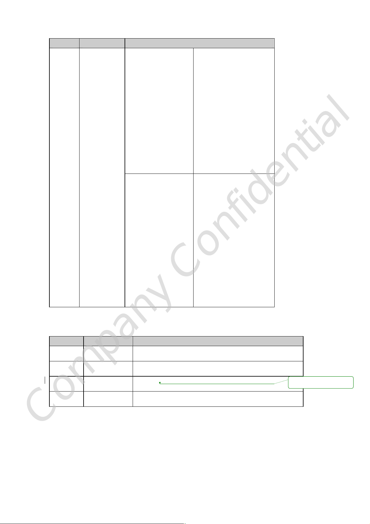
2.4 Regulatory Requirements
# Feature Detailed Description
2.4.1 United States IEEE 802.11a/n:
EMI: FCC Part 15.407(b)
Power Limits: FCC Part 15.407(a)
IEEE 802.11b/g/n:
FCC part 15.247, 15.205, 15.209
Safety:
UL1950-3 for CSA mark
2.4.2
2.4.3
2.4.4
2.4.5
Europe
Japan
Taiwan
Canada
IEEE 802.11a/n:
EMC: EN 301 489-1 and –17, EN 60950
Ÿ
DFS/TPC: 301 893
Ÿ
IEEE 802.11b/g/n:
EMC: EN 300 328, EN 300 826, EN 60950
Ÿ
IEEE 802.11a/n:
ARIB STD-T71
Ÿ
IEEE 802.11b/g/n:
ARIB STD-T66
Ÿ
EMI:
VCCI
Ÿ
IEEE 802.11a/b/g/n:
Ÿ NCC LP0002
IEEE 802.11a/b/g/n:
Power Limits: RSS-210 6.2.2 (91)
Ÿ
Safety:
CSA
Ÿ
Company Confidential
Page 13

2.5 Requirements of Reliability,
Maintainability and Quality
# Feature Detailed Description
2.5.1 MTBF
2.5.2
2.5.3
Maintainability
Quality
Mean Time Between Failure > 30,000 hours
Ÿ
There is no scheduled preventive maintenance required
Ÿ
The product quality is followed-up by Alpha Networks
Ÿ
factory quality control system
2.6 Environmental Requirements
# Feature Detailed Description
2.6.1 Operating
Temperature
Conditions
2.6.2
2.6.3 Operating
2.6.4
Non-Operating
Temperature
Conditions
Humidity
conditions
Non-Operating
Humidity
Conditions
Ÿ The product is capable of continuous reliable operation
when operating in ambient temperature of 0 ℃ to +40℃.
Neither subassemblies is damaged nor the operational
Ÿ
performance is degraded when restored to the operating
temperature after exposing to storage temperature in the
range of –20 ℃ to +75 ℃.
Ÿ The product is capable of continuous reliable operation when subjected
to relative humidity in the range of 10% and 90% non-condensing.
The product is not damaged nor the performance is
Ÿ
degraded after exposure to relative humidity ranging from
5% to 95% non-condensing
Company Confidential
Page 14

Federal Communication Commission Interference Statement
This equipment has been tested and found to comply with the limits for a Class B digital device,
pursuant to Part 15 of the FCC Rules. These limits are designed to provide reasonable protection
against harmful interference in a residential installation. This equipment generates, uses and can
radiate radio frequency energy and, if not installed and used in accordance with the instructions, may
cause harmful interference to radio communications. However, there is no guarantee that
interference will not occur in a particular installation. If this equipment does cause harmful
interference to radio or television reception, which can be determined by turning the equipment off
and on, the user is encouraged to try to correct the interference by one of the following measures:
- Reorient or relocate the receiving antenna.
- Increase the separation between the equipment and receiver.
- Connect the equipment into an outlet on a circuit different from that
to which the receiver is connected.
- Consult the dealer or an experienced radio/TV technician for help.
This device complies with Part 15 of the FCC Rules. Operation is subject to the following two
conditions: (1) This device may not cause harmful interference, and (2) this device must accept any
interference received, including interference that may cause undesired operation.
FCC Caution: Any changes or modifications not expressly approved by the party responsible for
compliance could void the user's authority to operate this equipment.
IMPORTANT NOTE:
FCC Radiation Exposure Statement:
This equipment complies with FCC radiation exposure limits set forth for an uncontrolled environment.
This equipment should be installed and operated with minimum distance 20cm between the radiator
& your body.
This transmitter must not be co-located or operating in conjunction with any other antenna or
transmitter.
Operations in the 5.15-5.25GHz band are restricted to indoor usage only
IEEE 802.11b or 802.11g operation of this product in the U.S.A. is firmware-limited to channels 1
through 11.
This device is intended only for OEM integrators under the following conditions:
1) The antenna must be installed such that 20 cm is maintained between the antenna and users,
and
2) The transmitter module may not be co-located with any other transmitter or antenna,
3) For all products market in US, OEM has to limit the operation channels in CH1 to CH11 for 2.4G
Company Confidential
Page 15

band by supplied firmware programming tool. OEM shall not supply any tool or info to the end-user
regarding to Regulatory Domain change.
As long as 3 conditions above are met, further transmitter test will not be required. However, the OEM
integrator is still responsible for testing their end-product for any additional compliance requirements
required with this module installed (for example, digital device emissions, PC peripheral requirements,
etc.).
IMPORTANT NOTE: In the event that these conditions can not be met (for example certain laptop
configurations or co-location with another transmitter), then the FCC authorization is no longer
considered valid and the FCC ID can not be used on the final product. In these circumstances, the OEM
integrator will be responsible for re-evaluating the end product (including the transmitter) and
obtaining a separate FCC authorization.
End Product Labeling
This transmitter module is authorized only for use in device where the antenna may be installed such
that 20 cm may be maintained between the antenna and users. The final end product must be labeled
in a visible area with the following: “Contains FCC ID: RRK-WMPND03B”.
Manual Information To the End User
The OEM integrator has to be aware not to provide information to the end user regarding how to
install or remove this RF module in the user’s manual of the end product which integrates this module.
The end user manual shall include all required regulatory information/warning as show in this manual.
Industry Canada Statement
This device complies with RSS-210 of the Industry Canada Rules. Operation is subject to the following
two conditions:
1) this device may not cause interference and
2) this device must accept any interference, including interference that may cause undesired
operation of the device
This device has been designed to operate with an antenna having a maximum gain of 6.63dBi (Peak
Gain, exclude cable loss)
Antenna having a higher gain is strictly prohibited per regulations of Industry Canada. The required
antenna impedance is 50 ohms.
To reduce potential radio interference to other users, the antenna type and its gain should be so
chosen that the EIRP is not more than required for successful communication.
Company Confidential
Page 16

Caution:
The device for the band 5150-5250 MHz is only for indoor usage to reduce potential for harmful
interference to co-channel mobile satellite systems.
Because high power radars are allocated as primary users (meaning they have priority) in 5250-5350
MHz and 5650-5850 MHz, these radars could cause interference and/or damage to license exempt
LAN devices.
In order to protect Environment Canada weather radars operating in the band 5600-5650 MHz, this
device will not transmit on any channels operating in the band 5600-5650 MHz,
IMPORTANT NOTE:
IC Radiation Exposure Statement:
This equipment complies with IC radiation exposure limits set forth for an uncontrolled environment.
This equipment should be installed and operated with minimum distance 20cm between the radiator
& your body.
This device is intended only for OEM integrators
under the following conditions:
The transmitter module may not be co-located with any other transmitter or antenna.
This device is intended only for OEM integrators under the following conditions:
1. The antenna must be installed such that 20 cm is maintained between the antenna and users,
and
2. The transmitter module may not be co-located with any other transmitter or antenna,
3. For all products market in CANADA, OEM has to limit the operation channels in CH1 to CH11 for
2.4G band by supplied firmware programming tool. OEM shall not supply any tool or info to the
end-user regarding to Regulatory Domain change.
As long as 3 conditions above are met, further transmitter test will not be required. However, the OEM
integrator is still responsible for testing their end-product for any additional compliance requirements
required with this module installed (for example, digital device emissions, PC peripheral requirements,
etc.).
As long as conduction above is met, further transmitter test will not be required. However, the OEM
integrator is still responsible for testing their end-product for any additional compliance requirements
required with this module installed (for example, digital device emissions, PC peripheral requirements,
etc.).
IMPORTANT NOTE: In the event that these conditions can not be met (for example certain laptop
configurations or co-location with another transmitter), then the IC authorization is no longer
considered valid and the IC ID can not be used on the final product. In these circumstances, the OEM
Company Confidential
Page 17

integrator will be responsible for re-evaluating the end product (including the transmitter) and
obtaining a separate IC authorization.
End Product Labeling
The final end product must be labeled in a visible area with the following: “Contains TX IC :
4833A-WMPND03B”.
Manual Information That Must be Included:
The OEM integrator has to be aware not to provide information to the end user regarding how to
install or remove.
This RF module in the user’s manual of the end product which integrates this module.
The user’s manual for OEM Integrators must include the following information in a prominent
location “IMPORTANT NOTE: To comply with FCC RF exposure compliance requirements. The antenna
must not be co-located or operating in conjunction with any other antenna or transmitter”.
If the end product integrating this module is going to be operated in 5.15 ~ 5.25GHz frequency range,
the warning statement in the user manual of the end product should include the restriction of
operating this device in indoor could void the user’s authority to operate the equipment.
以下警語適用台灣地區
經型式認證合格之低功率射頻電機,非經許可,公司、商號或使用者均不得擅自變更頻率、加大
功率或變更原設計之特性及功能。
低功率射頻電機之使用不得影響飛航安全及干擾合法通信;經發現有干擾現象時,應立即停用,
並改善至無干擾時方得繼續使用。前項合法通信,指依電信法規定作業之無線電通信。低功率射
頻電機須忍受合法通信或工業、科學及醫療用電波輻射性電機設備之干擾。
在5.25-5.35秭赫(GHz)頻帶內操作之無線資訊傳輸設備,限於室內使用。
本模組於取得認證後將依規定於模組本體標示審合格籤,並要求平台上標示「本產品內含射頻模
組:ID編號」
Company Confidential
 Loading...