

Page 1

User Manual
For
802.11 b/g/n Draft 2.0 Intelligent NIC Card
(Ralink RT3662)
Model Number : WMP-N13
Revision: 1.2
This document contains confidential proprietary information and is the property of Alpha Networks Inc.. The contents of
this document may not be disclosed to unauthorized persons without the written consent of Alpha Networks Inc..
Alpha Networks Proprietary and Confidential Information
Page 2

Revision History
Rev. Date Author Reason for Changes
1.0 2009/12/10 Amanda Wang
1.1 2009/12/17 Amanda Wang
1.2 2010/3/9 Amanda Wang
• New released
• Revise 11n HT20/40 Receiver Sensitivity
• Revise Block Diagram , 11b/g/n Transmitter Output
Power and receiver sensitivity numbers
• Revise Operating temperature / non-operating
temperature
Alpha Networks Proprietary and Confidential Information
ii
Page 3
Operation Manual
WMP-G15 Test Manual
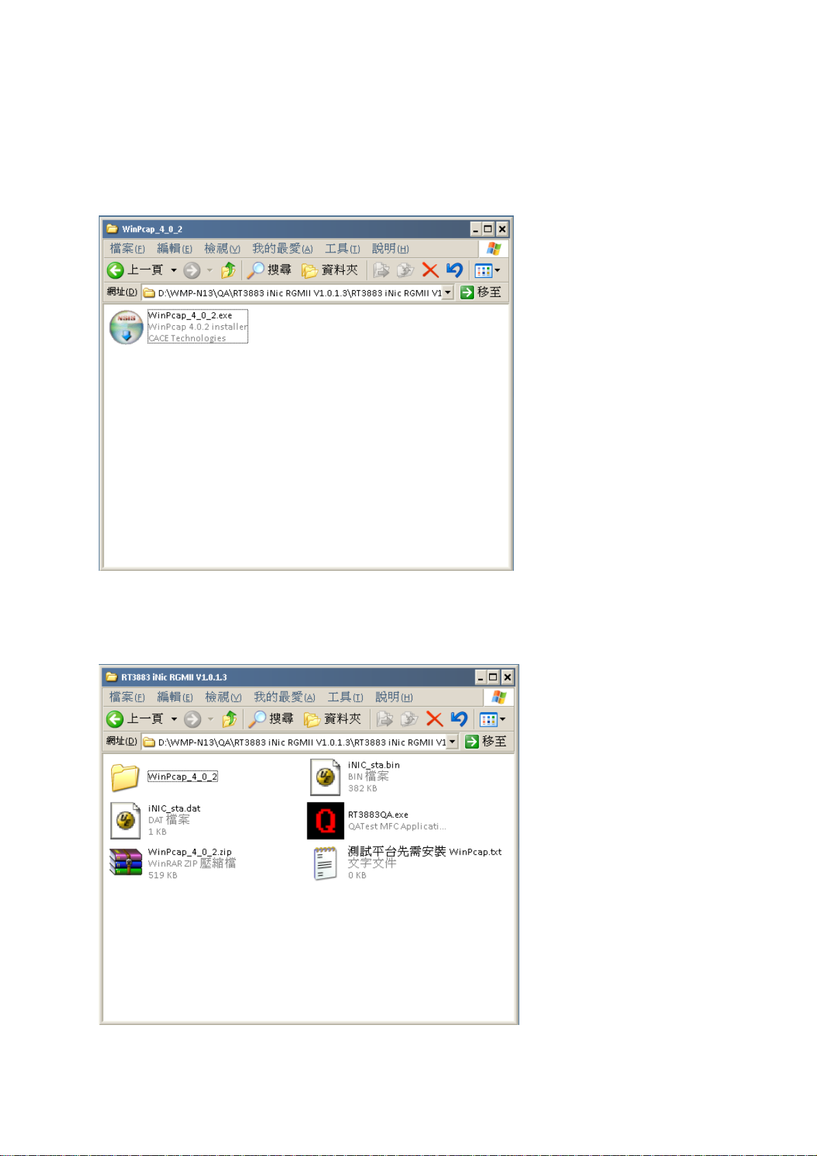
I. Install WinPcap
1. Run WinPcap_4_0_2.exe to install the WinPcap tool.
2. Insert the WMP-N13 card and turn on the test board.
3. Confirm the Ethernet link speed is 1000Mbps.
II. Run Test Utility
1. Run “RT3882QA.exe” to start test tool.
Alpha Networks Proprietary and Confidential Information
2
Page 4
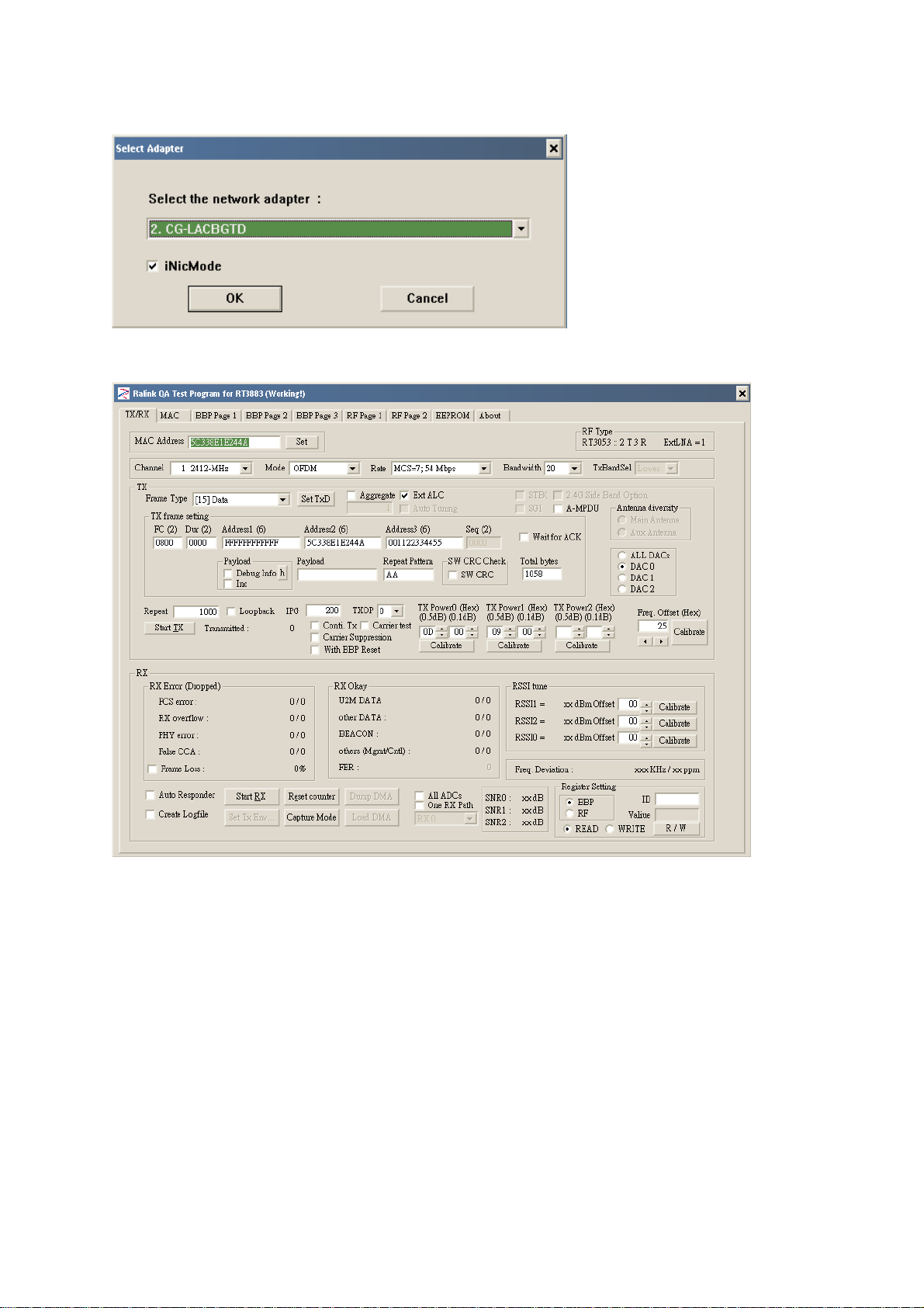
2. Select your Giga Ethernet adapter.
3. Start to TX/RX signal testing.
a. Select channel.
b. Select mode.
c. Select data rate.
d. Select bandwidth.
e. Select TX/RX path.
Start to transmit signal.
Alpha Networks Proprietary and Confidential Information
3
Page 5

Contents
1.0 SCOPE........................................................................................................................................................................... 5
1.1 DOCUMENT................................................................................................................................................................. 5
1.2 PRODUCT FEATURES.................................................................................................................................................. 5
2.0 REQUIREMENTS ....................................................................................................................................................... 6
2.1 FUNCTIONAL BLOCK DIAGRAM ................................................................................................................................ 6
2.2 GENERAL REQUIREMENTS ........................................................................................................................................ 6
2.2.1 IEEE 802.11b Section.......................................................................................................................................... 6
2.2.2 IEEE 802.11g Section.......................................................................................................................................... 7
2.2.3 IEEE 802.11n Section for 2.4G Band..............................................................................
2.3 General Section ........................................................................................................................................................... 8
2.4 SOFTWARE REQUIREMENTS .................................................................................................................................... 10
2.4.1 Information ........................................................................................................................................................ 10
2.4.2 Configuration .................................................................................................................................................... 10
2.4.3 Security .............................................................................................................................................................. 11
2.5 MECHANICAL REQUIREMENTS ............................................................................................................................... 11
2.6 COMPATIBILITY REQUIREMENTS ........................................................................................................................... 11
2.7 REQUIREMENTS OF RELIABILITY, MAINTAINABILITY AND QUALITY................................................................... 11
2.8 ENVIRONMENTAL REQUIREMENTS ......................................................................................................................... 11
APPENDIX I: ..................................................................................................................................錯誤! 尚未定義書籤。
錯誤
錯誤! 尚未定義書籤
尚未定義書籤。。。。
錯誤錯誤
尚未定義書籤尚未定義書籤
Alpha Networks Proprietary and Confidential Information
iii
Page 6

2.0 Requirements
The following sections identify the detailed requirements of the 802.11n Draft 2.0 mPCI .
2.1 Functional Block Diagram
2.2 General Requirements
2.2.1 IEEE 802.11b Section
# Feature Detailed Description
2.2.2.1 Standard
2.2.2.2 Radio and
Modulation
Schemes
2.2.2.3 Operating
Frequency
2.2.2.4 Channel Numbers
2.2.2.5 Data Rate
2.2.2.6 Media Access
Protocol
2.2.2.7 Transmitter Output
Power
2.2.2.8 Receiver Sensitivity
IEEE 802.11b
DQPSK, DBPSK, DSSS, and CCK
2400 ~ 2497MHz ISM band
11 channels for United States
13 channels for Europe Countries
14 channels for Japan
11, 5.5, 2, and 1Mbps
CSMA/CA with ACK
Typical RF Output Power (Tolerance +-2dB) at each RF chain, Data
Rate and at room Temp. 25degree C
18(±2dBm at 1,2,5.5,11Mbps
Typical Sensitivity at Which Frame (1000-byte PDUs) Error Rate =
8%
–80 dBm at 1Mbps
–80 dBm at 2Mbps
–76 dBm at 5.5Mbps
–76 dBm for 11Mbps
Alpha Networks Proprietary and Confidential Information
6
Page 7

2.2.2 IEEE 802.11g Section
# Feature Detailed Description
2.2.3.1 Standard
2.2.3.2 Radio and
IEEE 802.11g
BPSK, QPSK, 16QAM, 64QAM with OFDM
Modulation Type
2.2.3.3 Operating Frequency
2.2.3.4 Channel Numbers
2400 ~ 2483.5MHz ISM band
11 channels for United States
13 channels for Europe Countries
13 channels for Japan
2.2.3.5 Data Rate 6,9,12,18,24,36,48,54Mbps
2.2.3.6 Media Access
CSMA/CA with ACK
Protocol
2.2.3.7 Transmitter Output
Power
Typical RF Output Power (tolerance +-2dB) at each RF chain, Data
Rate and at room Temp. 25degree C
+ 18 dBm at 6, 9Mbps
+ 18 dBm at 12, 18Mbps
+ 17 dBm at 24, 36Mbps
+ 15 dBm at 48, 54 Mbps
2.2.3.8 Receiver Sensitivity
Typical Sensitivity at Which Frame (1000-byte PDUs) Error Rate =
10%
–82 dBm at 6Mbps
–81 dBm at 9Mbps
–79 dBm at 12Mbps
–77 dBm at 18Mbps
–74 dBm at 24Mbps
–70 dBm at 36Mbps
–66 dBm at 48Mbps
–65 dBm at 54Mbps
2.2.3 IEEE 802.11n Section for 2.4G Band
# Feature Detailed Description
2.2.3.1 Standard
2.2.3.2 Radio and
Draft n
BPSK, QPSK, 16QAM, 64QAM with OFDM
Modulation Type
2.2.3.3 Operating Frequency
2.2.3.4 MIMO
2.2.3.5 Data Rate
2.4GHz band: 2400 ~ 2483.5MHz
2T3R
0 6.5 13.5 7.2 15
1 13 27 14.4 30
2 19.5 40.5 21.7 45
3 26 54 28.9 60
4 39 81 43.3 90
5 52 108 57.8 120
6 58.5 121.5 65.0 135
7 65 135 72.2 150
8 13 27 14.444 30
9 26 54 28.889 60
10 39 81 43.333 90
11 52 108 57.778 120
12 78 162 86.667 180
13 104 216 115.556 240
14 117 243 130.000 170
15 130 270 144.444 300
16
17
18
GI=800ns GI=400ns MCS
20MHz 40MHz 20MHz 40MHz
19.5 40.5 21.7 45
39 81 43.3 90
58.5 121.5 65 135
Alpha Networks Proprietary and Confidential Information
7
Page 8

# Feature Detailed Description
2.2.3.6 Media Access
19
20
21
22
23
CSMA/CA with ACK
78 162 86.7 180
117 243 130 270
156 324 173.3 360
175.5 364.5 195 405
195 405 216.7 450
Protocol
2.2.3.7 Transmitter Output
Power at Antenna
Connector
2.2.3.8 Receiver Sensitivity
at Antenna
Connector
Typical RF Output Power (tolerance +-2dB) at each RF chain, Data
Rate and at room Temp. 25degree C
Note: The maximum power setting will vary according to individual country regulations.
2.4GHz Band/HT-20
+ 17dBm at MCS 0/1
+ 17dBm at MCS 2/3
+ 16dBm at MCS 4/5
+ 14dBm at MCS 6/7
Maximum Sensitivity at each RF chain at Which Frame (1000-byte
PDUs) Error Rate = 10% and at room Temp. 25degree C
2.4GHz Band/HT-20
–82 dBm at MCS0
–79 dBm at MCS1
–77 dBm at MCS2
–74 dBm at MCS3
–70 dBm at MCS4
–66 dBm at MCS5
–65 dBm at MCS6
–64 dBm at MCS7
2.4GHz Band/HT-40
+ 15dBm at MCS 0/1
+ 15dBm at MCS 2/3
+ 14dBm at MCS 4/5
+ 12dBm at MCS 6/7
2.4GHz Band/HT-40
–79 dBm at MCS0
–76 dBm at MCS1
–74 dBm at MCS2
–71 dBm at MCS3
–67 dBm at MCS4
–63 dBm at MCS5
–62 dBm at MCS6
–61 dBm at MCS7
2.3 General Section
# Feature Detailed Description
2.2.4.1 Antenna Connector
2.2.4.2 Operating Voltage
2.2.4.3 Current
Three UFL compatible antenna connectors
3.3VDC +/- 10%
1.2 A
Consumption
2.2.4.4 Form Factor and
PCI-E connector with RGMII signal
Interface
2.2.4.5 PCB Outline See below
2.2.4.6 Pin Assignment
See below
Alpha Networks Proprietary and Confidential Information
8
Page 9

Pin Name Type Pin Name Type
1 GND P 2 NC
3 GE_RXD3 I 4 NC
5 3.3V P 6 GND P
7 GE_RXD1 I 8 GND P
9 GND P 10 GND P
11 GE_RXD2 I 12 GND P
13 3.3V P 14 GE_MDC O
15 GE_RXDV I 16 GE_MDIO I/O
Mechanical Key
17 GND P 18 GND P
19 GE_RXD0 I 20 GND P
21 GND P 22 GND P
23 GE_RXCLK I 24 GND P
25 GND P 26 GND P
27 GND P 28 GND P
29 GE_TXD2 O 30 GND P
31 GND P 32 GND P
33 GE_TXD1 O 34 GND P
Alpha Networks Proprietary and Confidential Information
9
Page 10

35 3.3V P 36 GND P
37 GE_TXD0 O 38 GND P
39 GND P 40 NC
41 GE_TXCLK O 42 GND P
43 GND P 44 NC
45 GE_TXD3 O 46 GND P
47 3.3V P 48 iNIC_WLED O
49 GE_TXEN O 50 GND P
51 GND P 52 iNIC_RST# I
2.4 Software Requirements
The Configuration Software supports Linux2.6. This configuration software includes the following functions:
Information
Information allows you to monitor network status.
Configuration
Configuration allows you to configure parameters for wireless networking.
Security
Supports enhanced security WEP, 802.1x, WPA and WPA2.
2.4.1 Information
# Feature Detailed Description
2.4.1.1 General
Information
2.4.1.2 Current Link
Information
2.4.1.3 Site survey
2.4.2 Configuration
# Feature Detailed Description
2.4.2.1 ESS ID
2.4.2.2 Network Type
2.4.2.3 Power Save
2.4.2.4 RTS Threshold
2.4.2.5 Fragment Threshold
2.4.2.6 Transmission Speed
2.4.2.7 Roaming
General Information shows the name of Wireless
Adapter, Adapter MAC Address, Regulatory Domain,
Firmware Version, and Utility Version.
Current Link Information shows the Current Setting
ESSID, Channel Number, Associated BSSID, Network
Type, Security Status, Link Status, Transmit Speed,
Signal Strength, and Link Quality.
To search the neighboring access points and display the
information of all access points.
Input an SSID number if the roaming feature is enabled
Supports for ASCII printable characters.
Ad-hoc Mode and 802.11 Ad-hoc Mode for network
configurations that do not have any access points
Infrastructure Mode for network configurations with
access points
Extend the battery life of clients by allowing the client to
sleep for short periods of time while the Access Point
buffers the messages.
Set the number of bytes used for fragmentation boundary
for messages
Set the number of bytes used for RTS/CTS boundary
This indicates the communication rates. Select
appropriate transmission speed to match your wireless
LAN settings
Support Automatic or Manual Rescan to associate with
access point.
Alpha Networks Proprietary and Confidential Information
10
Page 11

2.4.3 Security
# Feature Detailed Description
2.4.3.1 Encryption RC4 encryption algorithm
Support 64-bit and 128-bit WEP encryption
Support open system (OSA) and shared key
authentication (SKA)
2.4.3.2 WEP Management Four WEP keys can be selected
STA with WEP off will never associate any AP with
WEP enabled
WEP Key Format: Option for Hex format
2.4.3.3 802.1x Support EAP-TLS, EAP-TTLS, and EAP-PEAP
2.4.3.4 WPA/WPA2
Support WPA/WPA2-PSK and WPA/WPA2-EAP
Support Cipher Mode AES and TKIP
2.5 Mechanical Requirements
# Feature Detailed Description
2.5.1 Length 72mm(max)
2.5.2 Width 48mm (+-0.25)
2.5.3 Height 1 mm (+-0.1)
2.6 Compatibility Requirements
This device passes the following compatibility requirements.
# Feature Detailed Description
2.6.1 Wi-Fi
2.6.2 WHQL
2.6.3 Physical Layer and
Functionality
Meet Wi-Fi certification for IEEE 802.11b/g/n product
Meet applicable WHQL certification requirements
Meet ALPHA Engineering Test Plan and Test Report
2.7 Requirements of Reliability, Maintainability and Quality
# Feature Detailed Description
2.7.1 MTBF
2.7.2 Maintainability
2.7.3 Quality
Mean Time Between Failure > 30,000 hours
There is no scheduled preventive maintenance required
The product quality is followed-up by ALPHA factory
quality control system
2.8 Environmental Requirements
# Feature Detailed Description
2.8.1 Operating
Temperature
Conditions
2.8.2 Non-Operating
Temperature
Conditions
2.8.3 Operating
Humidity
conditions
2.8.4 Non-Operating
Humidity
Conditions
The product is capable of continuous reliable operation
when operating in ambient temperature of 0℃ to +50℃.
Neither subassemblies is damaged nor the operational
performance is degraded when restored to the operating
temperature after exposing to storage temperature in the
range of -20 ℃ to +75℃.
The product is capable of continuous reliable operation
when subjected to relative humidity in the range of 10%
and 90% non-condensing.
The product is not damaged nor the performance is
degraded after exposure to relative humidity ranging
from 5% to 95% non-condensing
Alpha Networks Proprietary and Confidential Information
11
Page 12

Federal Communication Commission Interference Statement
This equipment has been tested and found to comply with the limits for a Class B digital
device, pursuant to Part 15 of the FCC Rules. These limits are designed to provide
reasonable protection against harmful interference in a residential installation. This
equipment generates, uses and can radiate radio frequency energy and, if not installed and
used in accordance with the instructions, may cause harmful interference to radio
communications. However, there is no guarantee that interference will not occur in a
particular installation. If this equipment does cause harmful interference to radio or television
reception, which can be determined by turning the equipment off and on, the user is
encouraged to try to correct the interference by one of the following measures:
- Reorient or relocate the receiving antenna.
- Increase the separation between the equipment and receiver.
- Connect the equipment into an outlet on a circuit different from that
to which the receiver is connected.
- Consult the dealer or an experienced radio/TV technician for help.
This device complies with Part 15 of the FCC Rules. Operation is subject to the following two
conditions: (1) This device may not cause harmful interference, and (2) this device must
accept any interference received, including interference that may cause undesired operation.
FCC Caution: Any changes or modifications not expressly approved by the party responsible
for compliance could void the user's authority to operate this equipment.
IMPORTANT NOTE:
FCC Radiation Exposure Statement:
This equipment complies with FCC radiation exposure limits set forth for an uncontrolled
environment. This equipment should be installed and operated with minimum distance 20cm
between the radiator & your body.
This transmitter must not be co-located or operating in conjunction with any other antenna or
transmitter.
IEEE 802.11b or 802.11g operation of this product in the U.S.A. is firmware-limited to
channels 1 through 11.
Page 13

This device is intended only for OEM integrators under the following conditions:
1) The antenna must be installed such that 20 cm is maintained between the antenna and
users, and
2) The transmitter module may not be co-located with any other transmitter or antenna,
3) For all products market in US, OEM has to limit the operation channels in CH1 to CH11
for 2.4G band by supplied firmware programming tool. OEM shall not supply any tool or info
to the end-user regarding to Regulatory Domain change.
As long as 3 conditions above are met, further transmitter test will not be required. However,
the OEM integrator is still responsible for testing their end-product for any additional
compliance requirements required with this module installed (for example, digital device
emissions, PC peripheral requirements, etc.).
IMPORTANT NOTE: In the event that these conditions can not be met (for example certain
laptop configurations or co-location with another transmitter), then the FCC authorization is no
longer considered valid and the FCC ID can not be used on the final product. In these
circumstances, the OEM integrator will be responsible for re-evalua t ing the end product
(including the transmitter) and obtaining a separate FCC authorization.
End Product Labeling
This transmitter module is authorized only for use in device where the antenna may be
installed such that 20 cm may be maintained between the antenna and users. The final end
product must be labeled in a visible area with the following: “Contains FCC ID:
RRK-WMPN13A1”.
Manual Information To the End User
The OEM integrator has to be aware not to provide information to the end user regarding how
to install or remove this RF module in the user’s manual of the end product which integrates
this module.
The end user manual shall include all required regulatory information/warning as show in this
manual.
 Loading...