

Page 1

WMP-N06
WMP-N06
User’s Guide
Page 2

WMP-N06
FCC Statement :
This device complies with Part 15 of the FCC Rules. Operation is subject to the following two conditions:
(1) This device may not cause harmful interference.
(2) This device must accept any interference received, including interference that may cause undesired
operation.
This equipment has been tested and found to comply with the limits for a class B digital device, pursuant to
part 15 of the FCC Rules. These limits are designed to provide reasonable protection against harmful
interference in a residential installation.
This equipment generates, uses and can radiate radio frequency energy and, if not installed and used in
accordance with the instructions, may cause harmful interference to radio communications. However, there
is no guarantee that interference will not occur in a particular installation. If this equipment does cause
harmful interference to radio or television reception, which can be determined by turning the equipment off
and on, the user is encouraged to try to correct the interference by one or more of the following measures:
---Reorient or relocate the receiving antenna.
---Increase the separation between the equipment and receiver.
---Connect the equipment into an outlet on a circuit different from that to which the receiver is connected.
---Consult the dealer or an experienced radio/TV technician for help.
Installation and use of this Wireless LAN device must be in strict accordance with the instructions included
in the user documentation provided with the product. Any changes or modifications (including the antennas)
made to this device that are not expressly approved by the manufacturer may void the user’s authority to
operate the equipment. The manufacturer is not responsible for any radio or television interference caused
by unauthorized modification of this device, or the substitution of the connecting cables and equipment
other than manufacturer specified. It is the responsibility of the user to correct any interference caused by
such unauthorized modification, substitution or attachment. Manufacturer and its authorized resellers or
distributors will assume no liability for any damage or violation of government regulations arising from
failing to comply with these guidelines.
FCC RF Radiation Exposure Statement:
1.This transmitter must not be co-located or operating in conjunction with any other antenna or transmitter.
2.This equipment complies with FCC RF radiation exposure limits set forth for an
uncontrolled environment. This equipment should be installed and operated with a minimum
distance of 20 centimeters between the radiator and your body.
Modular Approval
This device is intended only form OEM integrator under the following conditions:
1) The antenna must be installed such that 20cm is maintained between the antenna and users, and
2) The transmitter module may not be co-located with any other transmitter or antenna.
Page 3

IMPORTANT NOTE: In the event that these conditions cannot be met (for example certain laptop
configurations or co-location with another transmitter), then the FCC authorization is no longer considered
valid and the FCC ID cannot be used on the final product. In these circumstances, the OEM integrator will
be responsible for re-evaluating the end product (including the transmitter) and obtaining a separate FCC
authorization.
End Product Labeling
This transmitter module is authorized only for use in devices where the antenna may be installed such that
20 cm may be maintained between the antenna and users (for example access points, routers, wireless
ADSL modems, and similar equipment). The final end product must be labeled in visible area with the
following:
“Contains RF Module FCC ID: RRK2005110016-1
End Product Manual Information
The user manual for end users must include the following information in a prominent location
“IMPORTANT NOTE: To comply with FCC RF exposure compliance requirements, the antenna used for
this transmitter must be installed to provide a separation distance of at least 20cm from all persons and
must not be co-located or operating in conjunction with any other antenna or transmitter.”
WMP-N06
Page 4

p
WMP-N06
1.0 Scope
1.1 Document
This document is to specify the product requirements for 802.11b/g MIMO Mini-PCI Card. This MIMO Mini-PCI
Card is based on Atheros AR5008 chipset that complied with 802.11n draft 1.0 standard from 2.4~2.5GHz, and it can
be used to provide up to 11Mbps for IEEE 802.11b and 54Mbps for 2.4GHz IEEE 802.11g to connect your
wireless LAN.
With seamless roaming, fully interoperability and advanced security with WEP standard, 802.11b/g MIMO Mini-
PCI Card offers absolute interoperability with different vendors’ 802.11b/g MIMO Access Points through the
wireless LAN.
1.2 Product Features
Compatible with IEEE 802.11b high rate standard to provide wireless 11Mbps data rate
Compatible with IEEE 802.11g higher speed standard to provide wireless 54Mbps data rateo
Operation at 2.4 ~ 2.5GHz frequency band to meet worldwide regulations
Dynamic date rate scaling at 6, 9, 12, 18, 24, 36, 48, 54Mbps for 802.11g
Dynamic date rate scaling at 1, 2, 5.5, and 11Mbps for IEEE 802.11b
Compatible with IEEE 802.11n draft 1.0 higher speed standard in High Throughput mode from MCS-0 to
MCS-15. The HT data rate refers to Appendix A.
Maximum reliability, throughput and connectivity with automatic data rate switching
Supports wireless data encryption with 64/128/152-bit WEP for security
Supports infrastructure networks via Access Point and ad-hoc network via peer-to-peer communication
Dual UFL antenna connectors for diversity
Supports WPA and AES enhanced security
Supports VLAN tagging
Friendly user configuration and utilities
Drivers support Windows 98SE, ME, 2K, and XP
Supports Mini-PCI Type IIIA form factor
2.0 Requirements
The following sections identify the detailed requirements of the 802.11g/b MIMO Mini-PCI Card.
2.1 General Requirements
2.1.1 IEEE 802.11b Section
# Feature Detailed Description
2.1.1.1 Standard
2.1.1.2 Radio and
Modulation
Schemes
2.1.1.3 Operating
Frequency
2.1.1.4 Channel Numbers
IEEE 802.11b
DQPSK, DBPSK, DSSS, and CCK
2400 ~ 2497MHz ISM band
11 channels for United States
13 channels for Euro
e Countries
Page 5
2dBi Dipole Antenna: Typical 28dBm
3dBi Dipole Antenna: Typical 28dBm
2dBi Dipole Antenna: Typical 29dBm
3dBi Dipole Antenna: Typical 28dBm
# Feature Detailed Description
2.1.1.5 Data Rate
2.1.1.6 Media Access
Protocol
2.1.1.7 Transmitter Output
Power
2.1.1.8 Receiver Sensitivity Typical –84dBm for 11Mbps @ 8% PER
2.1.2 IEEE 802.11g Section
# Feature Detailed Description
2.1.2.1 Standard
2.1.2.2 Radio and
Modulation
Schemes
2.1.2.3 Operating
Frequency
2.1.2.4 Channel Numbers
2.1.2.5 Data Rate
2.1.2.6 Media Access
Protocol
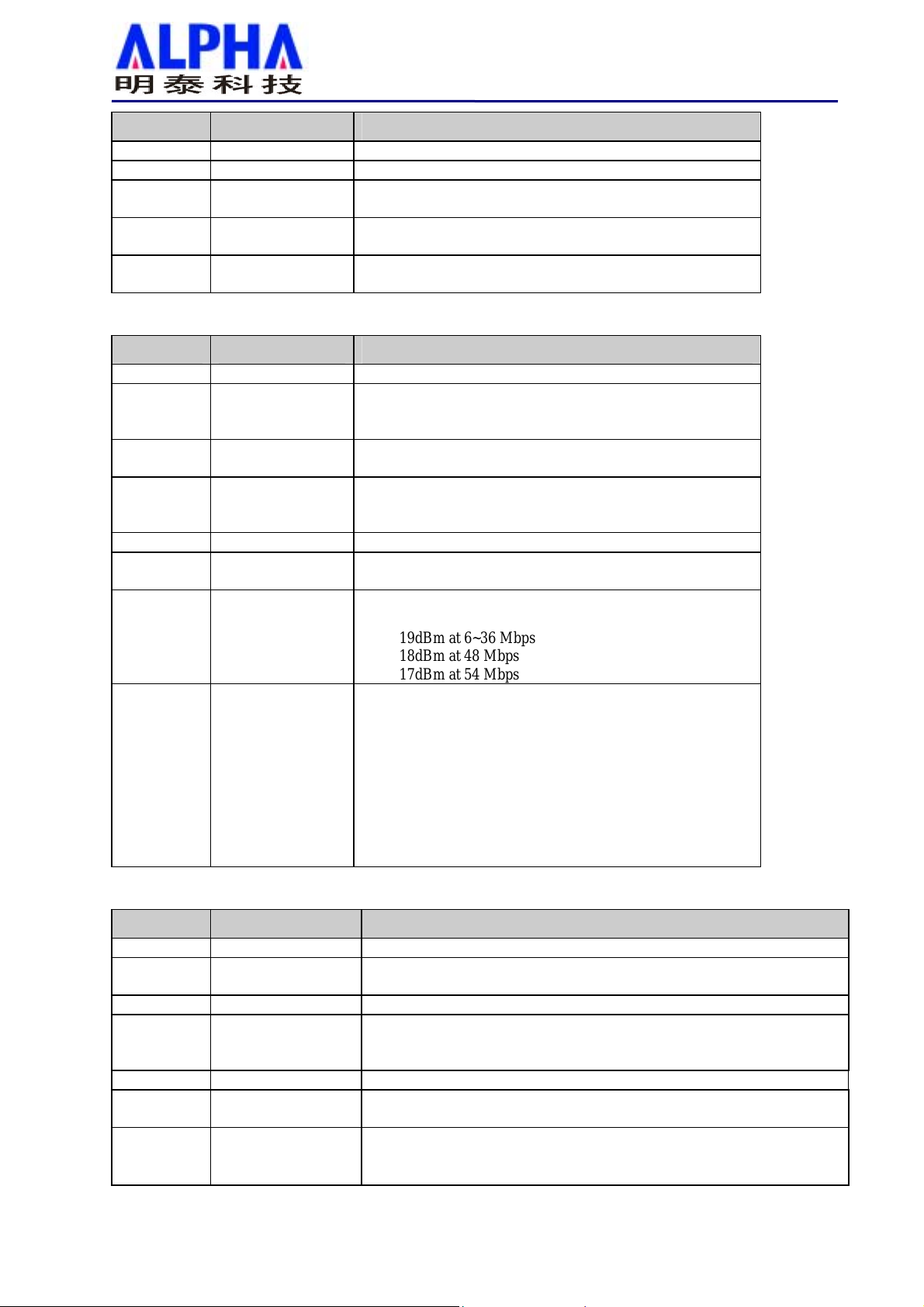
2.1.2.7 Transmitter Output
Power
2.1.2.8 Receiver Sensitivity Typical Sensitivity at Which Frame (1000-byte PDUs)
WMP-N06
14 channels for Japan
11, 5.5, 2, and 1Mbps
CSMA/CA with ACK
Typical –90dBm for 2Mbps @ 8% PER
IEEE 802.11g
BPSK, QPSK, 16QAM, 64QAM, and OFDM
2400 ~ 2483.5MHz ISM band
11 channels for United States
13 channels for Europe Countries
13 channels for Japan
6,9,12,18,24,36,48,54Mbps
CSMA/CA with ACK
Typical RF Output Power at each RF chain, Data Rate
and at room Temp. 25degree C_2dBi/3dBi dipole antenna
19dBm at 6~36 Mbps
18dBm at 48 Mbps
17dBm at 54 Mbps
Error Rate = 10%
–86dBm at 6Mbps
–86dBm at 9Mbps
–84dBm at 12Mbps
–82dBm at 18Mbps
–78dBm at 24Mbps
–75dBm at 36Mbps
–71dBm at 48Mbps
–70dBm at 54Mbps
2.1.3 High Throughput Section (HT Mode)
# Feature Detailed Description
2.1.3.1 Standard
2.1.3.2 Radio and
2.1.3.3 Operating Frequency 2400 ~ 2483.5MHz ISM band
2.1.3.4 Channel Numbers
2.1.3.5 Data Rate
2.1.3.6 Media Access
2.1.3.7 Transmitter Output
Modulation Type
Protocol
Power
IEEE 802.11n draft 1.0
BPSK, QPSK, 16QAM, 64QAM with OFDM
11 channels for United States
13 channels for Europe Countries
13 channels for Japan
From MCS – 0 to MCS –15 as shown in Appendix A
CSMA/CA with ACK
Typical RF Output Power at each RF chain, Data Rate and at room
Temp. 25degree C_2dBi/3dBi dipole antenna
Page 6

2dBi Dipole Antenna: Typical 29.5dBm
3dBi Dipole Antenna: Typical 29.5dBm
# Feature Detailed Description
2.1.3.8 Receiver Sensitivity
2.1.4 General Section
# Feature Detailed Description
2.1.4.1 Antenna Connector Dual UFL antenna connectors
2.1.4.2 Operating Voltage 3.3VDC +/- 10%
2.1.4.3 Current
Consumption
2.1.4.4 Form Factor and
Interface
2.1.4.5 LEDs
WMP-N06
15dBm at MCS - 5, 13
11dBm at MCS - 6, 14
6dBm at MCS - 7, 15
Typical Sensitivity at Which Frame (1000-byte PDUs) Error Rate =
10%
–88dBm at BPSK, coding rate 1/2 (MCS-0)
–84dBm at QPSK, coding rate 1/2 (MCS-1)
–81dBm at QPSK, coding rate 3/4 (MCS-2)
–78dBm at 16-QAM, coding rate 1/2 (MCS-3)
–75dBm at 16-QAM, coding rate 3/4 (MCS-4)
–70dBm at 64-QAM, coding rate 2/3 (MCS-5)
–69dBm at 64-QAM, coding rate 3/4 (MCS-6)
–68dBm at 64-QAM, coding rate 5/6 (MCS-7)
800mA at continuous transmit mode (2 Tx chains on )
450mA at continuous receive mode (3 Rx chains on )
Mini-PCI Type IIIA form factor
External LED function supported
2.2 Software Requirements
The Configuration Software supports Microsoft Windows 98SE, ME, 2000, and XP. This configuration software
includes the following functions:
Information
Information allows you to monitor network status.
Configuration
Configuration allows you to configure parameters for wireless networking.
Security
Supports enhanced security WEP, 802.1x,WPA.
2.2.1 Information
# Feature Detailed Description
2.2.1.1 General
Information
2.2.1.2 Current Link
Information
2.2.1.3 Site survey
General Information shows the name of Wireless
Adapter, Adapter MAC Address, Regulatory Domain,
Firmware Version, and Utility Version.
Current Link Information shows the Current Setting
ESSID, Channel Number, Associated BSSID, Network
Type (infrastructure or Ad-hoc network), WEP Status
(enable or disable), Link Status (Connect or Disconnect), 802.11g Transmit Speed (6, 9, 12, 18, 24, 36,
48, 54Mbps), 802.11b Transmit Speed (1, 2, 5.5,
11Mbps), Signal Strength, and Link Quality.
To search the neighboring access points and display the
information of all access points.
Page 7

2.2.2 Configuration
# Feature Detailed Description
2.2.2.1 ESS ID
2.2.2.2 Network Type
2.2.2.3 Power Save
2.2.2.4 RTS Threshold
2.2.2.5 Fragment
Threshold
2.2.2.6 Transmission Speed This indicates the communication rates. Select
2.2.2.7 Roaming
WMP-N06
Input an SSID number if the roaming feature is enabled
Supports for ASCII printable characters.
Ad-hoc Mode and 802.11 Ad-hoc Mode for network
configurations that do not have any access points
Infrastructure Mode for network configurations with
access points
Extend the battery life of clients by allowing the client
to sleep for short periods of time while the Access Point
buffers the messages.
Set the number of bytes used for fragmentation
boundary for messages
Set the number of bytes used for RTS/CTS boundary
appropriate transmission speed to match your wireless
LAN settings
Support Automatic or Manual Rescan to associate with
access point.
2.2.3 Security
# Feature Detailed Description
2.2.3.1 Encryption RC4 encryption algorithm
Support 64/128/152 bit WEP encryption
Support open system and shared key authentication
2.2.3.2 WEP Management Four WEP keys can be selected
STA with WEP off will never associate any AP with
WEP enabled
WEP Key Format: Option for Hex format
2.2.3.3 802.1x
2.2.3.4 WPA
Support EAP-TLS, EAP-TTLS, and EAP-PEAP
Support WPA-PSK and WPA-EAP
Support Cipher Mode AES and TKIP
2.3 Mechanical Requirements
# Feature Detailed Description
2.3.1 Length 50.8mm
2.3.2 Width 59.59mm
2.3.3 Height 0.99mm
2.4 Compatibility Requirements
This device passes the following compatibility requirements.
# Feature Detailed Description
2.4.1 Wi-Fi
2.4.2 WHQL
2.4.3 Physical Layer and
Functionality
Meet Wi-Fi certification for IEEE 802.11 product
Meet applicable WHQL certification requirements
Meet ALPHA Engineering Test Plan and Test Report
2.5 Requirements of Reliability, Maintainability and Quality
# Feature Detailed Description
2.5.1 MTBF
2.5.2 Maintainability There is no scheduled preventive maintenance required
Mean Time Between Failure > 30,000 hours
Page 8

# Feature Detailed Description
2.5.3 Quality
WMP-N06
The product quality is followed-up by ALPHA factory
quality control system
2.6 Environmental Requirements
# Feature Detailed Description
2.6.1 Operating
Temperature
Conditions
2.6.2 Non-Operating
Temperature
Conditions
2.6.3 Operating
Humidity
conditions
2.6.4 Non-Operating
Humidity
Conditions
The product is capable of continuous reliable operation
when operating in ambient temperature of 0 ℃ to +55℃.
Neither subassemblies is damaged nor the operational
performance is degraded when restored to the operating
temperature after exposing to storage temperature in the
range of –20 ℃ to +75 ℃.
The product is capable of continuous reliable operation
when subjected to relative humidity in the range of 10%
and 90% non-condensing.
The product is not damaged nor the performance is
degraded after exposure to relative humidity ranging
from 5% to 95% non-condensing
Page 9

WMP-N06
Test Environment Diagram/測試環境圖示
Fixed Attenuator (30dB) * 3 pcs
Splitter (1 對 3)
IP: 192.168.100.254
(Note:For IQ-View / IQ-Flex)
Page 10

WMP-N06
Normal Test Operating Procedure/一般作業用測試操作程序
1. Testing Steps:
8 steps in total
1. 測試步驟: 共 8 個步驟
註 1:測試前請先安裝待測物之 driver.
註 2:測試前請先依照附錄(Test Programming Setup / 測試程式設定說明)設定
[Step 1] Run ” BC_LOG.exe ” at DUT (see Figure 1) to open test window (see Figure 2).
[步驟 1] 執行 DUT 端上的” BC_LOG.exe ”(如圖 1)開啟如圖 2 測試畫面。
Ex: C:\Program Files\LitePoint\IQfact\ART_MIMO_1WMPN06…B1G\MINIPCI_2071\ BC_LOG.exe
(Figure 1)
(Figure 2)
Page 11

[Step 2] Run ” GUI.exe ” at DUT (see Fi gure 3) to open test window (see Figure 4).
[步驟 2] 執行 DUT 端上的” GUI.exe ”(如圖 3)開啟如圖 4 測試畫面。
Ex: C:\Program Files\LitePoint\IQfact\ART_MIMO_1WMPN06…B1G\MINIPCI_2071\ GUI.exe
(Figure 3)
WMP-N06
(Figure 4)
Page 12

[Step 3] Then Kevin Serial number (see Figure 5)
[步驟 3] 鍵入 Serial Number (如圖 5
(Figure 5)
WMP-N06
[Step 4] (a) Plug DUT into MINI PCI / CARD BUS Interface
(b) Plug RF Cable on DUT antenna three point and user a special line
(MAIN-From Left to Right 0.1.2)
[步驟 4] (a) 將待測物插入 MINI PCI / CARD BUS Interface 介面。
(b) 將待測物接上測試線於三個天線端,請使用專用測試線。(MAIN-由左至右 0.1.2)
[Step 5] Click “Run Production Test Soft ware” to begin test. (See Figure 6)
[步驟 5] 按下” Run Production Test Software”開始測試(如圖 6)。
(Figure 6)
Page 13

[Step 6] Testing. (See Figure 7)
[步驟 6] 測試中(如圖 7)。
(Figure 7)
WMP-N06
Page 14

[Step 7] When test finish, it will show “PASS”(see Figure 8).
[步驟 7] 當測試完成,會出現’’PASS”的視窗(圖8)。
(Figure 8)
WMP-N06
[Step 8] When show “PASS”, click “ Test ” and change the next one to continue (see Figure 8).
[步驟 8] 出現 PASS 畫面,按” T est “鍵並換下一片繼續[步驟3]到[步驟 8]。(如圖 7)。
Page 15

WMP-N06
Test Program setup / 測試程式設定
[步驟 1] 尋找程式中” IQ_attn.txt ” 檔案(如圖 1),
(Ex: Ex: C:\Program Files\LitePoint\IQfact\ART_MIMO_1WMPN06…B1G\MINIPCI_2071\iq_setup\ IQ_attn.txt)
(Figure 1)
註1: 請依當時 Cable loss 填入: (Ex: IQ_FIXED_ATTEN_2_4_CHAIN0 = 38.5)
(Ex: IQ_FIXED_ATTEN_2_4_CHAIN1 = 38.5)
(Ex: IQ_FIXED_ATTEN_2_4_CHAIN2 = 38.5)
Page 16

[步驟 2] 測試 Fail (如圖 2),
(Figure 2)
WMP-N06
 Loading...