

Page 1
Manual
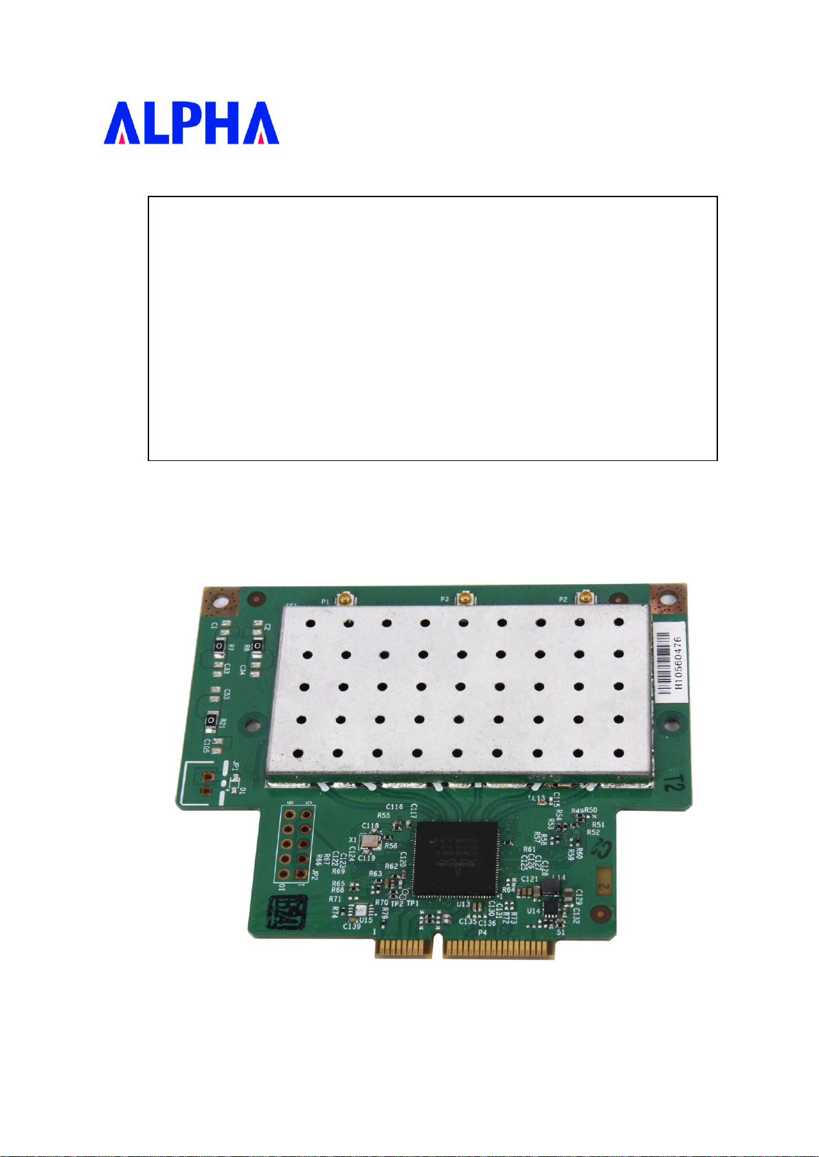
WMC-AC01
Wireless AC Module
Revision: 1.0
Page 2

Contents
1.0 SCOPE ........................................................................................................................................................................... 3
1.1 DOCUMENT ................................................................................................................................................................. 3
1.2 PRODUCT FEATURES .................................................................................................................................................. 3
2.0 REQUIREMENTS ....................................................................................................................................................... 3
2.1 FUNCTIONAL BLOCK DIAGRAM ................................................................................................................................ 3
2.2 GENERAL REQUIREMENTS ........................................................................................................................................ 4
2.2.1 IEEE 802.11a Section .......................................................................................................................................... 5
2.2.2 IEEE 802.11n Section. ............................................................................................................................... ………5
2.2.3 IEEE 802.11ac Section…………………………………………………………………………………………………… .7
2.2.4 General Section ................................................................................................................................................... 7
2.3 SOFTWARE REQUIREMENTS ...................................................................................................................................... 7
2.3.1 Security ................................................................................................................................................................ 8
2.4 MECHANICAL REQUIREMENTS ................................................................................................................................. 8
2.5 COMPATIBILITY REQUIREMENTS ............................................................................................................................. 8
2.6 REQUIREMENTS OF RELIABILITY, MAINTAINABILITY AND QUALITY ..................................................................... 8
2.7 ENVIRONMENTAL REQUIREMENTS ........................................................................................................................... 8
ii
Page 3
1.0 Scope
1.1 Document
This document is to specify the product requirements for 802.11ac PCI Express. This PCI Express card is based on BCM chip
that complied with IEEE 802.11ac from 5GHz, and it is also backward compatible to comply with IEEE 802.11a and IEEE
802.11n standard.
1.2 Product Features
Compatible with IEEE 802.11a high rate standard to provide wireless 54Mbps data rate
Compatible with IEEE 802.11n draft standard to provide wireless 300Mbps data rate
Compatible with IEEE 802.11ac draft standard to provide wireless 1300Mbps data rate
Operation at 5.15~5.85GHz frequency band to meet worldwide regulations
Supports WEP, 802.1x, WPA and WPA2 enhanced security
Friendly user configuration and diagnostic utilities
Support Linux driver.
Supports PCIe interface .
2.0 Requirements
The following sections identify the detailed requirements of the 802.11ac PCI Express.
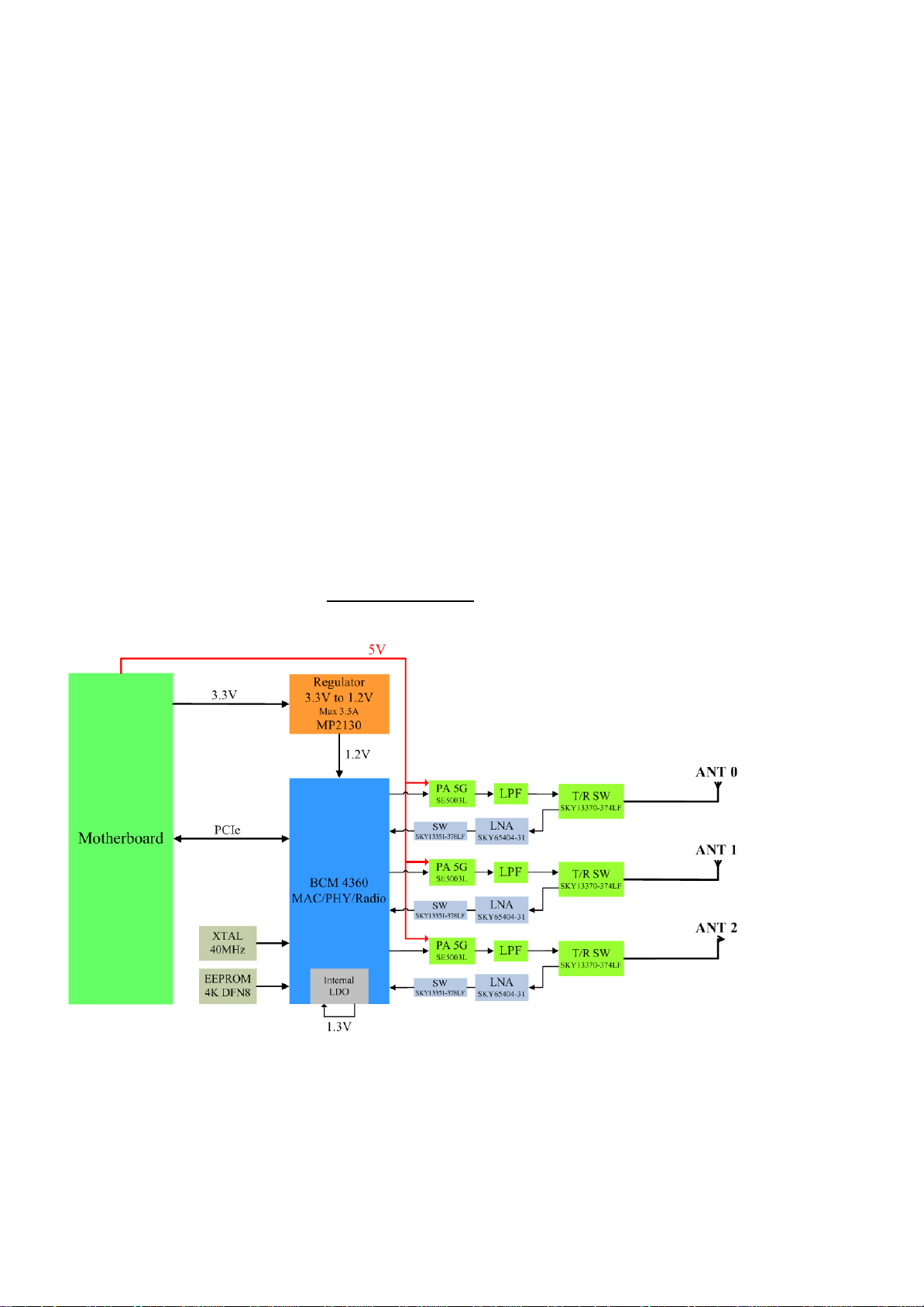
2.1 Functional Block Diagram : BCM-4360 (PCI-e)
3
Page 4
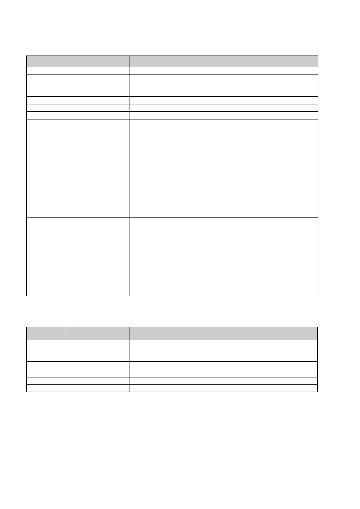
2.2 General Requirements
Feature
Detailed Description
2.2.1.1
Standard IEEE 802.11a
2.2.1.2
Radio and Modulation
Schemes
BPSK, QPSK, 16QAM, 64QAM, with OFDM
2.2.1.3
Operating Frequency
5150MHz~5250MHz,5725MHz~5850MHz
2.2.1.4
Channel Numbers
Ch36~CH64/CH149~CH165
2.2.1.5
Data Rate 54, 48, 36, 24, 18, 12, 9, and 6 Mbps
2.2.1.6
Media Access Protocol
CSMA/CA with ACK
2.2.1.7
Transmitter Output
Power
Frequency 5180~5240MHz
Typical RF Output Power at each RF chain, Data Rate and at room
Temp. 25degree C ( tolerance ± 2dB )
8 dBm (+/-2dB) at 6 to 9 Mbps
8 dBm (+/-2dB) at12~24 Mbps
8 dBm (+/-2dB) at 36~54 Mbps
Frequency 5745~5825MHz
Typical RF Output Power at each RF chain, Data Rate and at room
Temp. 25degree C ( tolerance ± 2dB )
20 dBm (+/-2dB) at 6 to 9 Mbps
20 dBm (+/-2dB) at12~24 Mbps
18 dBm (+/-2dB) at 36~54 Mbps
Note: The maximum RF output power setting is different by channel and
individual country regulations.
2.2.1.8
Effective Isotropic
Radiated Power
EIRP17.5dbm@ CH36~CH64
EIRP29.5dbm@ CH149~CH165
2.2.1.9
Receiver Sensitivity
Error Rate = 10% at room temperature.
–82dBm at 6Mbps
–81dBm at 9Mbps
–79dBm at 12Mbps
–77dBm at 18Mbps
–74dBm at 24Mbps
–70dBm at 36Mbps
–66dBm at 48Mbps
–65dBm at 54Mbps
Feature
Detailed Description
2.2.2.1
Standard IEEE 802.11n
2.2.2.2
Radio and Modulation
Schemes
BPSK, QPSK, 16QAM, 64QAM with OFDM
2.2.2.3
Operating Frequency
5150MHz~5250MHz,5725MHz~5850MHz
2.2.2.4
Channel Numbers
Ch36~CH48 , CH149~CH165 for IEEE 802.11a/n
2.2.2.5
Data Rate
6.5~300 Mbps
2.2.2.6
Media Access Protocol
CSMA/CA with ACK
2.2.1 IEEE 802.11a Section
2.2.2 IEEE 802.11n Section
4
Page 5

Feature
Detailed Description
2.2.2.7
Transmitter Output
Power
N mode HT20 (5180MHz~5240MHz)
Typical RF Output Power at each RF chain, Data Rate and at room
Temp. 25degree C ( tolerance ± 2dB )
Typical 10dBm (+/-2dB) at MCS0 to MCS23
N mode HT40 (5180MHz~5240MHz)
Typical 12dBm (+/-2dB) at MCS0 to MCS23
N mode HT20 (5745MHz~58250MHz)
Typical 20dBm (+/-2dB) at MCS0/1 and MCS8/9 and MCS16/17
Typical 20dBm (+/-2dB) at MCS2~ MCS4 and MCS10~MCS12 and
MCS18~MCS20
Typical 18dBm (+/-2dB) at MCS5~MCS7 and MCS 13~MCS15 and
MCS21~MCS23
N mode HT40 (5745MHz~58250MHz)
Typical 20dBm (+/-2dB) at MCS0/1 and MCS8/9 and MCS16/17
Typical 20dBm (+/-2dB) at MCS2~ MCS4 and MCS10~MCS12 and
MCS18~MCS20
Typical 18dBm (+/-2dB) at MCS5~MCS7 and MCS 13~MCS15 and
MCS21~MCS23
Note: The maximum RF output power setting is different by channel and
individual country regulations.
2.2.2.8
Effective Isotropic
Radiated Power
EIRP20.5dbm@ CH36~CH48
EIRP29.5dbm@ CH149~CH165
2.2.2.9
Receiver Sensitivity
N mode HT20(MHZ)
-82dBm at (MCS0/8/16)
-79dBm at (MCS1/9/17)
-77dBm at (MCS2/10/18)
-74dBm at (MCS3/11/19)
-70dBm at (MCS4/12/20)
-66dBm at (MCS5/13/21)
-65dBm at (MCS6/14/22)
-64dBm at (MCS7/15/23)
N mode HT40(MHZ)
-79dBm at (MCS0/8/16)
-76dBm at (MCS1/9/17)
-74dBm at (MCS2/10/18)
-71dBm at (MCS3/11/19)
-67dBm at (MCS4/12/20)
-63dBm at (MCS5/13/21)
-62dBm at (MCS6/14/22)
-61dBm at (MCS7/15/23)
5
Page 6

2.2.3 IEEE 802.11ac Section
#
Feature
Detailed Description
2.2.3.1
Standard IEEE 802.11ac
2.2.3.2
Radio and Modulation
Schemes
BPSK, QPSK, 16QAM, 64QAM , up to 256QAM with OFDM
2.2. 3.3
Operating Frequency
5150MHz~5250MHz, 5725MHz~5850MHz
2.2. 3.4
Channel Numbers
CH42 , CH155 for IEEE 802.11a/n
2.2. 3.5
Data Rate 6.5~1300 Mbps
2.2. 3.6
Media Access Protocol
CSMA/CA with ACK
2.2.3.7
Transmitter Output
Power
Typical RF Output Power at each RF chain, Data Rate and at room
Temp. 25degree C ( tolerance ± 2dB )
VHT 20 (5180MHz~5240MHz)
Typical RF Output Power at each RF chain, Data Rate and at room
Temp. 25degree C ( tolerance ± 2dB )
Typical 10dBm (+/-2dB) at MCS0 to MCS9
VHT40 /VHT80 (5180MHz~5240MHz)
Typical 11dBm (+/-2dB) at MCS0 to MCS9
VHT20 (5745MHz~58250MHz)
Typical 20dBm (+/-2dB) at MCS0/1,
Typical 20dBm (+/-2dB) at MCS2~ MCS4
Typical 18dBm (+/-2dB) at MCS5~MCS7
Typical 14dBm (+/-2dB) at MCS8/9
VHT40 (5745MHz~58250MHz)
Typical 20dBm (+/-2dB) at MCS0/1
Typical 20dBm (+/-2dB) at MCS2~ MCS4
Typical 18dBm (+/-2dB) at MCS5~MCS7
Typical 14dBm (+/-2dB) at MCS8/9
VHT80 (5755MHz)
Typical 20dBm (+/-2dB) at MCS0/1
Typical 20dBm (+/-2dB) at MCS2~ MCS4
Typical 18dBm (+/-2dB) at MCS5~MCS7
Typical 14dBm (+/-2dB) at MCS8/9
Note: The maximum RF output power setting is different by channel and
individual country regulations.
2.2. 3..8
Effective Isotropic
Radiated Power
EIRP20.5dBm@ CH36~CH48
EIRP29.5dBm@CH149~CH165
6
Page 7

#
Feature
Detailed Description
2.2. 3..9
Receiver Sensitivity
VHT 20
-82dBm at (MCS0)
-79dBm at (MCS1)
-77dBm at (MCS2)
-74dBm at (MCS3)
-70dBm at (MCS4)
-66dBm at (MCS5)
-65dBm at (MCS6)
-64dBm at (MCS7)
-59dBm at (MCS8)
-57dBm at (MCS9)
VHT 40
-79dBm at (MCS0)
-76dBm at (MCS1)
-74dBm at (MCS2)
-71dBm at (MCS3)
-67dBm at (MCS4)
-63dBm at (MCS5)
-62dBm at (MCS6)
-61dBm at (MCS7)
-56dBm at (MCS8)
-54dBm at (MCS9)
VHT 80
-76dBm at (MCS0)
-73dBm at (MCS1)
-71dBm at (MCS2)
-68dBm at (MCS3)
-64dBm at (MCS4)
-60dBm at (MCS5)
-59dBm at (MCS6)
-58dBm at (MCS7)
-53dBm at (MCS8)
-51dBm at (MCS9)
#
Feature
Detailed Description
2.2.4.1
Antenna Connector
Three UFL compatible antenna connectors
2.2.4.2
Operating Voltage
5VDC +/- 5%
2.2.4.3
Current
Consumption
5.1W is use on continue TX
2.2.4.4
Form Factor and
Interface
Mini-card form factor with signal of PCI-e Gen1 X1 lane
2.2.4 General Section
2.3 Software Requirements
The Configuration Software supports Linux driver. This configuration software includes the following functions:
Information
Information allows you to monitor network status.
7
Page 8

#
Feature
Detailed Description
2.3.1.1
Encryption
RC4 encryption algorithm
Support 64-bit and 128-bit WEP encryption
Support open system (OSA) and shared key authentication (SKA)
2.3.1.2
WEP Management
Four WEP keys can be selected
STA with WEP off will never associate any AP with WEP enabled
WEP Key Format: Option for Hex format
2.3.1.3
802.1x Support EAP-TLS, EAP-TTLS, and EAP-PEAP
2.3.1.4
WPA/WPA2
Support WPA/WPA2-PSK and WPA/WPA2-EAP
Support Cipher Mode AES and TKIP
#
Feature
Detailed Description
2.4.1
Length
77 mm (PCB)
2.4.2
Width
66 mm (PCB)
2.4.3
Height
1mm (PCB)
#
Feature
Detailed Description
2.5.1
Wi-Fi Meet Wi-Fi certification for IEEE 802.11a/n product
2.5.2
Physical Layer and
Functionality
Meet Alpha Networks Engineering Test Plan and Test Report
2.5.3
Green Part
Compliance to RoHS.
#
Feature
Detailed Description
2.6.1
MTBF Mean Time Between Failure > 30,000 hours
2.6.2
Maintainability
There is no scheduled preventive maintenance required
2.6.3
Quality The product quality is followed-up by ALPHA factory quality control
system
#
Feature
Detailed Description
2.7.1
Operating
Temperature
Conditions
The product is capable of continuous reliable operation when operating
in ambient temperature of 0 ℃ to +40℃.
2.7.2
Non-Operating
Temperature
Conditions
Neither subassemblies is damaged nor the operational performance is
degraded when restored to the operating temperature after exposing to
storage temperature in the range of –20 ℃ to +75 ℃.
2.7.3
Operating
Humidity
conditions
The product is capable of continuous reliable operation when subjected
to relative humidity in the range of 10% and 90% non-condensing.
2.7.4
Non-Operating
Humidity
Conditions
The product is not damaged nor the performance is degraded after
exposure to relative humidity ranging from 5% to 95% non-condensing
Configuration
Configuration allows you to configure parameters for wireless networking.
Security
Supports enhanced security WEP, 802.1x, WPA and WPA2.
2.3.1 Security
2.4 Mechanical Requirements
2.5 Compatibility Requirements
This device passes the following compatibility requirements.
2.6 Requirements of Reliability, Maintainability and Quality
2.7 Environmental Requirements
8
Page 9

Industry Canada statement:
This device complies with RSS-210 of the Industry Canada Rules. Operation is
subject to the following two conditions: (1) This device may not cause harmful
interference, and (2) this device must accept any interference received, including
interference that may cause undesired operation.
Ce dispositif est conforme à la norme CNR-210 d'Industrie Canada applicable aux
appareils radio exempts de licence. Son fonctionnement est sujet aux deux conditions
suivantes: (1) le dispositif ne doit pas produire de brouillage préjudiciable, et (2) ce
dispositif doit accepter tout brouillage reçu, y compris un brouillage susceptible de
provoquer un fonctionnement indésirable.
Radiation Exposure Statement:
This equipment complies with IC radiation exposure limits set forth for an
uncontrolled environment. This equipment should be installed and operated with
minimum distance 20cm between the radiator & your body.
Déclaration d'exposition aux radiations:
Cet équipement est conforme aux limites d'exposition aux rayonnements IC établies
pour un environnement non contrôlé. Cet équipement doit être installé et utilisé avec
un minimum de 20 cm de distance entre la source de rayonnement et votre corps.
Page 10

This device is intended only for OEM integrators under the following conditions: (For
module device use)
1) The antenna must be installed such that 20 cm is maintained between the antenna
and users, and
2) The transmitter module may not be co-located with any other transmitter or
antenna.
As long as 2 conditions above are met, further transmitter test will not be required.
However, the OEM integrator is still responsible for testing their end-product for any
additional compliance requirements required with this module installed.
Cet appareil est conçu uniquement pour les intégrateurs OEM dans les conditions
suivantes: (Pour utilisation de dispositif module)
1) L'antenne doit être installée de telle sorte qu'une distance de 20 cm est respectée
entre l'antenne et les utilisateurs, et
2) Le module émetteur peut ne pas être coïmplanté avec un autre émetteur ou antenne.
Tant que les 2 conditions ci-dessus sont remplies, des essais supplémentaires sur
l'émetteur ne seront pas nécessaires. Toutefois, l'intégrateur OEM est toujours
responsable des essais sur son produit final pour toutes exigences de conformité
supplémentaires requis pour ce module installé.
Page 11

IMPORTANT NOTE:
In the event that these conditions can not be met (for example certain laptop
configurations or co-location with another transmitter), then the Canada authorization
is no longer considered valid and the IC ID can not be used on the final product. In
these circumstances, the OEM integrator will be responsible for re-evaluating the end
product (including the transmitter) and obtaining a separate Canada authorization.
NOTE IMPORTANTE:
Dans le cas où ces conditions ne peuvent être satisfaites (par exemple pour certaines
configurations d'ordinateur portable ou de certaines co-localisation avec un autre
émetteur), l'autorisation du Canada n'est plus considéré comme valide et l'ID IC ne
peut pas être utilisé sur le produit final. Dans ces circonstances, l'intégrateur OEM
sera chargé de réévaluer le produit final (y compris l'émetteur) et l'obtention d'une
autorisation distincte au Canada.
End Product Labeling
This transmitter module is authorized only for use in device where the antenna may be
installed such that 20 cm may be maintained between the antenna and users. The final
end product must be labeled in a visible area with the following: “Contains IC:
4833A-WMCAC01A1”.
Plaque signalétique du produit final
Ce module émetteur est autorisé uniquement pour une utilisation dans un dispositif où
l'antenne peut être installée de telle sorte qu'une distance de 20cm peut être maintenue
entre l'antenne et les utilisateurs. Le produit final doit être étiqueté dans un endroit
visible avec l'inscription suivante: "Contient des IC: 4833A-WMCAC01A1".
Manual Information To the End User
The OEM integrator has to be aware not to provide information to the end user
regarding how to install or remove this RF module in the user’s manual of the end
product which integrates this module.
The end user manual shall include all required regulatory information/warning as
show in this manual.
Page 12

Manuel d'information à l'utilisateur final
L'intégrateur OEM doit être conscient de ne pas fournir des informations à l'utilisateur
final quant à la façon d'installer ou de supprimer ce module RF dans le manuel de
l'utilisateur du produit final qui intègre ce module.
Le manuel de l'utilisateur final doit inclure toutes les informations réglementaires
requises et avertissements comme indiqué dans ce manuel.
Caution :
(i) the device for operation in the band 5150-5250 MHz is only for indoor use to
reduce the potential for harmful interference to co-channel mobile satellite systems;
(ii) the maximum antenna gain permitted for devices in the band 5725-5825 MHz
shall comply with the e.i.r.p. limits specified for point-to-point and non point-to-point
operation as appropriate.
Avertissement:
Le guide d’utilisation des dispositifs pour réseaux locaux doit inclure des instructions
précises sur les restrictions susmentionnées, notamment :
(i) les dispositifs fonctionnant dans la bande 5 150-5 250 MHz sont réservés
uniquement pour une utilisation à l’intérieur afin de réduire les risques de brouillage
préjudiciable aux systèmes de satellites mobiles utilisant les mêmes canaux;
(ii) le gain maximal d’antenne permis (pour les dispositifs utilisant la bande 5 725-5
825 MHz) doit se conformer à la limite de p.i.r.e. spécifiée pour l’exploitation point à
point et non point à point, selon le cas.
Page 13

Federal Communication Commission Interference Statement
This device complies with Part 15 of the FCC Rules. Operation is subject to
the following two conditions: (1) This device may not cause harmful
interference, and (2) this device must accept any interference received,
including interference that may cause undesired operation.
This equipment has been tested and found to comply with the limits for a
Class B digital device, pursuant to Part 15 of the FCC Rules. These limits
are designed to provide reasonable protection against harmful interference in a
residential installation. This equipment generates, uses and can radiate radio
frequency energy and, if not installed and used in accordance with the
instructions, may cause harmful interference to radio communications.
However, there is no guarantee that interference will not occur in a particular
installation. If this equipment does cause harmful interference to radio or
television reception, which can be determined by turning the equipment off
and on, the user is encouraged to try to correct the interference by one of the
following measures:
- Reorient or relocate the receiving antenna.
- Increase the separation between the equipment and receiver.
- Connect the equipment into an outlet on a circuit different from that
to which the receiver is connected.
- Consult the dealer or an experienced radio/TV technician for help.
FCC Caution: Any changes or modifications not expressly approved by the
party responsible for compliance could void the user's authority to operate this
equipment.
This transmitter must not be co-located or operating in conjunction with any
other antenna or transmitter.
For operation within 5.15 ~ 5.25GHz GHz frequency range, it is restricted to
indoor environment. This device meets all the other requirements specified in
Part 15E, Section 15.407 of the FCC Rules.
Page 14

Radiation Exposure Statement:
This equipment complies with FCC radiation exposure limits set forth for an
uncontrolled environment. This equipment should be installed and operated
with minimum distance 20cm between the radiator & your body.
This device is intended only for OEM integrators under the following conditions:
1) The antenna must be installed such that 20 cm is maintained between the
antenna and users, and
2) The transmitter module may not be co-located with any other transmitter
or antenna.
As long as 2 conditions above are met, further transmitter test will not be
required. However, the OEM integrator is still responsible for testing their
end-product for any additional compliance requirements required with this
module installed
IMPORTANT NOTE: In the event that these conditions can not be met (for
example certain laptop configurations or co-location with another transmitter),
then the FCC authorization is no longer considered valid and the FCC ID can
not be used on the final product. In these circumstances, the OEM integrator
will be responsible for re-evaluating the end product (including the transmitter)
and obtaining a separate FCC authorization.
End Product Labeling
This transmitter module is authorized only for use in device where the antenna
may be installed such that 20 cm may be maintained between the antenna and
users. The final end product must be labeled in a visible area with the following:
“Contains FCC ID: RRK2012060056-1”. The grantee's FCC ID can be used only
when all FCC compliance requirements are met.
Manual Information To the End User
The OEM integrator has to be aware not to provide information to the end user
regarding how to install or remove this RF module in the user’s manual of the
end product which integrates this module.
The end user manual shall include all required regulatory information/warning as
show in this manual.
 Loading...