

Page 1

User Guide
Gateway 7001 Series Access Point
Page 2

Contents
1 Introduction . . . . . . . . . . . . . . . . . . . . . . . . . . . . . . . . . . . . . . . . . . . . . . . . . . . . . . 1
Overview of the Gateway 7001 Series of self-managed APs . . . . . . . . . . . . . . . . . . 2
Features and benefits . . . . . . . . . . . . . . . . . . . . . . . . . . . . . . . . . . . . . . . . . . . . . . . . 3
Default settings and supported administrator/client platforms . . . . . . . . . . . . . . . . . 5
Gateway 7001 Series self-managed AP . . . . . . . . . . . . . . . . . . . . . . . . . . . . . . . 5
Administrator’s computer . . . . . . . . . . . . . . . . . . . . . . . . . . . . . . . . . . . . . . . . . . . . . . 9
Wireless client computers . . . . . . . . . . . . . . . . . . . . . . . . . . . . . . . . . . . . . . . . . . . . 11
Understanding dynamic and static IP addressing . . . . . . . . . . . . . . . . . . . . . . . . . . 12
How does the access point obtain an IP address at startup? . . . . . . . . . . . . . 12
Dynamic IP addressing . . . . . . . . . . . . . . . . . . . . . . . . . . . . . . . . . . . . . . . . . . . 12
Static IP addressing . . . . . . . . . . . . . . . . . . . . . . . . . . . . . . . . . . . . . . . . . . . . . 13
Recovering an IP Address . . . . . . . . . . . . . . . . . . . . . . . . . . . . . . . . . . . . . . . . 13
2 Quick Setup. . . . . . . . . . . . . . . . . . . . . . . . . . . . . . . . . . . . . . . . . . . . . . . . . . . . . 15
Setting up the access point . . . . . . . . . . . . . . . . . . . . . . . . . . . . . . . . . . . . . . . . . . . 16
Unpacking the access point . . . . . . . . . . . . . . . . . . . . . . . . . . . . . . . . . . . . . . . 16
Connecting the access point to network and power . . . . . . . . . . . . . . . . . . . . . 17
Setting up connections for a guest network . . . . . . . . . . . . . . . . . . . . . . . . . . . 19
Turning on the access point . . . . . . . . . . . . . . . . . . . . . . . . . . . . . . . . . . . . . . . 20
Running KickStart to find access points and assign IP addresses . . . . . . . . . 20
Logging on to the administration Web pages . . . . . . . . . . . . . . . . . . . . . . . . . . 24
Configuring basic settings and starting the wireless network . . . . . . . . . . . . . . 27
What’s next? . . . . . . . . . . . . . . . . . . . . . . . . . . . . . . . . . . . . . . . . . . . . . . . . . . . 28
3 Configuring Basic Network Settings . . . . . . . . . . . . . . . . . . . . . . . . . . . . 29
Navigating to basic settings . . . . . . . . . . . . . . . . . . . . . . . . . . . . . . . . . . . . . . . . . . . 30
Reviewing and describing the access point . . . . . . . . . . . . . . . . . . . . . . . . . . . . . . 31
Providing administrator password and wireless network name . . . . . . . . . . . . . . . 32
Setting configuration policy for new access points . . . . . . . . . . . . . . . . . . . . . . . . . 34
Updating basic settings . . . . . . . . . . . . . . . . . . . . . . . . . . . . . . . . . . . . . . . . . . . . . . 36
Understanding basic settings for a standalone access point . . . . . . . . . . . . . . . . . 37
Understanding indicator icons . . . . . . . . . . . . . . . . . . . . . . . . . . . . . . . . . . . . . . . . . 38
4 Managing Access Points and Clusters . . . . . . . . . . . . . . . . . . . . . . . . . . 39
Introduction . . . . . . . . . . . . . . . . . . . . . . . . . . . . . . . . . . . . . . . . . . . . . . . . . . . . . . . . 40
Navigating to access points management . . . . . . . . . . . . . . . . . . . . . . . . . . . . . . . . 41
Understanding clustering . . . . . . . . . . . . . . . . . . . . . . . . . . . . . . . . . . . . . . . . . . . . . 42
What is a cluster? . . . . . . . . . . . . . . . . . . . . . . . . . . . . . . . . . . . . . . . . . . . . . . . 42
How many APs can a cluster support? . . . . . . . . . . . . . . . . . . . . . . . . . . . . . . 42
What kinds of APs can cluster together? . . . . . . . . . . . . . . . . . . . . . . . . . . . . . 42
Which settings are shared in the cluster configuration and which are not? . . 43
www.gateway.com
i
Page 3

Cluster mode . . . . . . . . . . . . . . . . . . . . . . . . . . . . . . . . . . . . . . . . . . . . . . . . . . . 44
Standalone mode . . . . . . . . . . . . . . . . . . . . . . . . . . . . . . . . . . . . . . . . . . . . . . . . 44
Cluster formation . . . . . . . . . . . . . . . . . . . . . . . . . . . . . . . . . . . . . . . . . . . . . . . . 45
Cluster size and membership . . . . . . . . . . . . . . . . . . . . . . . . . . . . . . . . . . . . . . 45
Intra-cluster security . . . . . . . . . . . . . . . . . . . . . . . . . . . . . . . . . . . . . . . . . . . . . . 45
Auto-Synch of Cluster Configuration . . . . . . . . . . . . . . . . . . . . . . . . . . . . . . . . . 46
Understanding access point settings . . . . . . . . . . . . . . . . . . . . . . . . . . . . . . . . . . . . 47
Working with access points in a cluster . . . . . . . . . . . . . . . . . . . . . . . . . . . . . . . . . . 48
Modifying the location description . . . . . . . . . . . . . . . . . . . . . . . . . . . . . . . . . . . 48
Removing an access point from the cluster . . . . . . . . . . . . . . . . . . . . . . . . . . . 48
Adding an access point to a cluster . . . . . . . . . . . . . . . . . . . . . . . . . . . . . . . . . 49
Navigating to information for a specific AP and managing standalone APs . . . . . .50
Navigating to an AP by using its IP address in a URL . . . . . . . . . . . . . . . . . . . 50
5 Managing User Accounts. . . . . . . . . . . . . . . . . . . . . . . . . . . . . . . . . . . . . . . . 51
Introduction . . . . . . . . . . . . . . . . . . . . . . . . . . . . . . . . . . . . . . . . . . . . . . . . . . . . . . . . 52
Navigating to user management for clustered access points . . . . . . . . . . . . . . . . . 53
Viewing and changing user accounts . . . . . . . . . . . . . . . . . . . . . . . . . . . . . . . . . . . 54
Viewing user accounts . . . . . . . . . . . . . . . . . . . . . . . . . . . . . . . . . . . . . . . . . . . . 54
Adding a user . . . . . . . . . . . . . . . . . . . . . . . . . . . . . . . . . . . . . . . . . . . . . . . . . . . 54
Editing a user account . . . . . . . . . . . . . . . . . . . . . . . . . . . . . . . . . . . . . . . . . . . . 55
6 Session Monitoring. . . . . . . . . . . . . . . . . . . . . . . . . . . . . . . . . . . . . . . . . . . . . . 57
Navigating to session monitoring . . . . . . . . . . . . . . . . . . . . . . . . . . . . . . . . . . . . . . . 58
Understanding session monitoring information . . . . . . . . . . . . . . . . . . . . . . . . . . . . 59
Viewing session information for access points . . . . . . . . . . . . . . . . . . . . . . . . . . . . 61
Sorting session information . . . . . . . . . . . . . . . . . . . . . . . . . . . . . . . . . . . . . . . . 61
Refreshing session information . . . . . . . . . . . . . . . . . . . . . . . . . . . . . . . . . . . . . 61
7 Advanced Configuration. . . . . . . . . . . . . . . . . . . . . . . . . . . . . . . . . . . . . . . . . 63
Configuring an Ethernet (wired) interface . . . . . . . . . . . . . . . . . . . . . . . . . . . . . . . . 64
Navigating to Ethernet (wired) settings . . . . . . . . . . . . . . . . . . . . . . . . . . . . . . . 65
Setting the DNS name . . . . . . . . . . . . . . . . . . . . . . . . . . . . . . . . . . . . . . . . . . . . 65
Enabling or Disabling Guest Access . . . . . . . . . . . . . . . . . . . . . . . . . . . . . . . . . 66
Specifying a physical or virtual Guest network . . . . . . . . . . . . . . . . . . . . . . . . . 66
Configuring Internal interface Ethernet settings . . . . . . . . . . . . . . . . . . . . . . . . 67
Configuring Guest interface Ethernet settings . . . . . . . . . . . . . . . . . . . . . . . . . . 69
Configuring a wireless interface . . . . . . . . . . . . . . . . . . . . . . . . . . . . . . . . . . . . . . . . 70
Navigating to wireless settings . . . . . . . . . . . . . . . . . . . . . . . . . . . . . . . . . . . . . 70
Configuring the radio interface . . . . . . . . . . . . . . . . . . . . . . . . . . . . . . . . . . . . . 70
Configuring internal LAN wireless settings . . . . . . . . . . . . . . . . . . . . . . . . . . . . 71
Configuring guest network wireless settings . . . . . . . . . . . . . . . . . . . . . . . . . . . 72
Enabling a network time protocol server . . . . . . . . . . . . . . . . . . . . . . . . . . . . . . . . . 74
Navigating to time protocol settings . . . . . . . . . . . . . . . . . . . . . . . . . . . . . . . . . 74
Enabling or disabling a network time protocol (NTP) server . . . . . . . . . . . . . . 75
ii
www.gateway.com
Page 4

Configuring network security . . . . . . . . . . . . . . . . . . . . . . . . . . . . . . . . . . . . . . . . . . 76
Understanding security issues on wireless networks . . . . . . . . . . . . . . . . . . . . 76
How do I know which security mode to use? . . . . . . . . . . . . . . . . . . . . . . . . . . 76
Navigating to security settings . . . . . . . . . . . . . . . . . . . . . . . . . . . . . . . . . . . . . 83
Configuring security settings . . . . . . . . . . . . . . . . . . . . . . . . . . . . . . . . . . . . . . . 83
Setting up Guest Access . . . . . . . . . . . . . . . . . . . . . . . . . . . . . . . . . . . . . . . . . . . . . 95
Understanding the guest interface . . . . . . . . . . . . . . . . . . . . . . . . . . . . . . . . . . 95
Configuring the guest interface . . . . . . . . . . . . . . . . . . . . . . . . . . . . . . . . . . . . . 96
Using the guest network as a client . . . . . . . . . . . . . . . . . . . . . . . . . . . . . . . . . 98
Deployment example . . . . . . . . . . . . . . . . . . . . . . . . . . . . . . . . . . . . . . . . . . . . . 99
Configuring radio settings . . . . . . . . . . . . . . . . . . . . . . . . . . . . . . . . . . . . . . . . . . . 100
Understanding radio settings . . . . . . . . . . . . . . . . . . . . . . . . . . . . . . . . . . . . . . 100
Navigating to radio settings . . . . . . . . . . . . . . . . . . . . . . . . . . . . . . . . . . . . . . . 101
Configuring radio settings . . . . . . . . . . . . . . . . . . . . . . . . . . . . . . . . . . . . . . . . 102
Controlling access by MAC address filtering . . . . . . . . . . . . . . . . . . . . . . . . . . . . . 106
Navigating to MAC filtering settings . . . . . . . . . . . . . . . . . . . . . . . . . . . . . . . . 106
Using MAC address filtering . . . . . . . . . . . . . . . . . . . . . . . . . . . . . . . . . . . . . . 107
Configuring a Wireless Distribution System (WDS) . . . . . . . . . . . . . . . . . . . . . . . 108
Understanding the WDS . . . . . . . . . . . . . . . . . . . . . . . . . . . . . . . . . . . . . . . . . 108
Navigating to WDS settings . . . . . . . . . . . . . . . . . . . . . . . . . . . . . . . . . . . . . . 111
Configuring WDS settings . . . . . . . . . . . . . . . . . . . . . . . . . . . . . . . . . . . . . . . . 112
Setting the administrator password . . . . . . . . . . . . . . . . . . . . . . . . . . . . . . . . . . . . 117
Navigating to administrator password setting . . . . . . . . . . . . . . . . . . . . . . . . . 117
Setting the administrator password . . . . . . . . . . . . . . . . . . . . . . . . . . . . . . . . . 117
8 Maintenance and Monitoring . . . . . . . . . . . . . . . . . . . . . . . . . . . . . . . . . . . 119
Introduction . . . . . . . . . . . . . . . . . . . . . . . . . . . . . . . . . . . . . . . . . . . . . . . . . . . . . . . 120
Interfaces . . . . . . . . . . . . . . . . . . . . . . . . . . . . . . . . . . . . . . . . . . . . . . . . . . . . . . . . 121
Ethernet (Wired) settings . . . . . . . . . . . . . . . . . . . . . . . . . . . . . . . . . . . . . . . . . 122
Wireless settings . . . . . . . . . . . . . . . . . . . . . . . . . . . . . . . . . . . . . . . . . . . . . . . 122
Event log . . . . . . . . . . . . . . . . . . . . . . . . . . . . . . . . . . . . . . . . . . . . . . . . . . . . . . . . 123
Transmit/receive statistics . . . . . . . . . . . . . . . . . . . . . . . . . . . . . . . . . . . . . . . . . . . 124
Associated wireless clients . . . . . . . . . . . . . . . . . . . . . . . . . . . . . . . . . . . . . . . . . . 126
Rebooting the access point . . . . . . . . . . . . . . . . . . . . . . . . . . . . . . . . . . . . . . . . . . 127
Resetting the configuration . . . . . . . . . . . . . . . . . . . . . . . . . . . . . . . . . . . . . . . . . . 128
Upgrading the firmware . . . . . . . . . . . . . . . . . . . . . . . . . . . . . . . . . . . . . . . . . . . . . 129
A Glossary . . . . . . . . . . . . . . . . . . . . . . . . . . . . . . . . . . . . . . . . . . . . . . . . . . . . . . . 131
B Specifications . . . . . . . . . . . . . . . . . . . . . . . . . . . . . . . . . . . . . . . . . . . . . . . . . . 153
C Safety, Regulatory, and Legal Information . . . . . . . . . . . . . . . . . . . . . 155
Index . . . . . . . . . . . . . . . . . . . . . . . . . . . . . . . . . . . . . . . . . . . . . . . . . . . . . . . . . . . . . 163
www.gateway.com
iii
Page 5

iv
www.gateway.com
Page 6

Chapter 1
■ Features and benefits
Introduction
■ Networking
■ Maintainability
■ Default settings and supported
administrator/client platforms
1
Page 7

Chapter 1: Introduction
Overview of the Gateway 7001 Series of
self-managed APs
The Gateway 7001 Series of self-managed APs (access points) provide continuous,
high-speed access between your wireless and Ethernet devices. They are advanced, turnkey
solutions for wireless networking in small and medium-sized businesses. The Gateway 7001
Series enables zero-administration wireless local area network (WLAN) deployment while
providing state-of-the-art wireless networking features.
The Gateway 7001 AP is available as a single band access point (Gateway 7001 802.11 G
Wireless Access Point) and a dual band access point (Gateway 7001 802.11 A+G Wireless
Access Point).
The single band access point can broadcast in either IEEE 802.11b or IEEE 802.11g mode.
The dual band access point is capable of broadcasting in two different IEEE 802.11 modes
simultaneously.
■ Radio One can broadcast in IEEE 802.11b or IEEE 802.11g modes.
■ Radio Two can broadcast in IEEE 802.11a or IEEE 802.11a Turbo modes.
The Gateway 7001 AP software solution emphasizes security, ease-of-administration and
industry standards—providing a standalone and fully secured wireless network without
the need for additional management applications such as legacy authentication server
software.
The following sections list features and benefits of the Gateway 7001 Series self-managed
APs, and tell you what’s next when you’re ready to get started.
2
www.gateway.com
Page 8

Features and benefits
Features and benefits
IEEE standards support and Wi-Fi compliance
■ Support for IEEE 802.11a, 802.11b, and 802.11g wireless networking standards
(depending on model)
■ Provides bandwidth of up to 54 Mbps for 802.11a or 802.11g (11 Mbps for 802.11b,
108 Mbps for 802.11a Turbo)
■ Wi-Fi certified
Wireless features
■ Auto channel selection at startup
■ Transmit power adjustment
■ Wireless Distribution System (WDS) for connecting multiple access points wirelessly.
Extends your network with less cabling and provides a seamless experience for roaming
clients.
■ Virtual Local Area Network (VLAN) support
■ Under-the-hood support for multiple SSIDs (network names) and multiple BSSIDs (basic
service set IDs) on the same access point
Security features
■ Inhibit SSID Broadcast
■ Ignore SSID Broadcast
■ Link integrity monitoring
■ Link integrity checking
■ Weak IV avoidance
■ Wireless Equivalent Privacy (WEP)
■ Wi-Fi Protected Access (WPA)
■ Advanced Encryption Standard (AES)
■ User-based access control with local authentication server
■ Local user database and user lifecycle management
■ MAC address filtering
Out-of-the-Box guest interface
■ Unique network name (SSID) for the Guest interface
■ Captive portal to guide guests to customized, guest-only Web page
www.gateway.com
3
Page 9

Chapter 1: Introduction
■ VLAN and dual Ethernet options
Clustering and auto-management
■ Automatic setup with Kickstart.
■ Provisioning and plug-and-play through automatic clustering and cluster rendezvous.
The administrator can specify how new access points should be configured before they
are added to the network. When new access points are added, they can automatically
rendezvous with the cluster, and securely download the correct configuration. The
process does not require manual intervention, but is under the control of the
administrator.
■ Single universal view of clustered access points and cluster configuration settings.
Configuration for all access points in a cluster can be managed from a single interface.
Changes to common parameters are automatically reflected in all members of the
cluster.
■ Self-managed access points with automatic configuration synchronization.
The access points in a cluster periodically check that the cluster configuration is
consistent, and check for the presence and availability of the other members of the
cluster. The administrator can monitor this information through the user interface.
■ Enhanced local authentication using 802.1x without additional IT setup.
A cluster can maintain a user authentication server and database stored on the access
points. This eliminates the need to install, configure, and maintain a RADIUS
infrastructure, and simplifies the administrative task of deploying a secure wireless
network.
■ Hardware watchdog.
Networking
■ Dynamic Host Configuration Protocol (DHCP) support for dynamically assigning
network configuration information to systems on the LAN
Maintainability
■ Status, monitoring, and tracking views of the network including session monitoring,
client associations, transmit/receive statistics, and event log
■ Reset configuration option
■ Firmware upgrade
4
www.gateway.com
Page 10

Default settings and supported administrator/client platforms
Default settings and supported
administrator/client platforms
Before you plug in and boot a new access point, review the following sections for a quick
check of required hardware components, software, client configurations, and compatibility
issues. Make sure you have everything you need ready to go for a successful launch and
test of your new (or extended) wireless network.
■ Gateway 7001 Series self-managed AP
■ Administrator’s computer
■ Wireless client computers
■ Understanding of DHCP IP addressing for access points and wireless clients
Gateway 7001 Series self-managed AP
The Gateway 7001 Series self-managed AP is a wireless communications hub for devices
on your network. It provides continuous, high-speed access between your wireless and
Ethernet devices in IEEE 802.11a, 802.11b, 802.11g, or 802.11a Turbo modes (depending
on the model).
The Gateway 7001 Series self-managed AP offers an out-of-the-box Guest Interface feature
that lets you configure access points for controlled guest access of the wireless network.
This can be accomplished either by using Virtual LANs or by creating physically separate
network connections on the same access point. To support physically separate network
connections, the Gateway 7001 Series self-managed AP ships with an extra network port
to be used for a dedicated guest network. (For more information on the guest interface,
see “Advanced Configuration” on page 63, and “Setting up connections for a guest
network” on page 19.)
Default settings for the Gateway 7001 Series self-managed AP
Option Default Settings Related Information
System Name Gateway-AP “Setting the DNS name”
on page 65
User Name admin
The user name is read-only. It cannot be
modified.
www.gateway.com
5
Page 11

Chapter 1: Introduction
Option Default Settings Related Information
Password admin “Providing administrator
password and wireless
network name” on
page 32
“Setting the
administrator password”
on page 117
Network Name (SSID) “Gateway 7001 AP Network” for the
Internal interface
“Gateway 7001 AP Guest Network” for the
Guest interface
Network Time Protocol
(NTP)
IP Address 192.168.1.1
Connection Type Dynamic Host Configuration Protocol
None “Enabling a network
The default IP address is used if you do not
use a Dynamic Host Configuration
Protocol (DHCP) server. You can assign a
new static IP address through the
Administration Web pages.
If you have a DHCP server on the network,
then an IP address will be dynamically
assigned by the server at AP startup.
(DHCP)
If you do not have a DHCP server on the
Internal network and do not plan to use
one, the first thing you must do after
bringing up the access point is to change
the Connection Type from “DHCP” to
“Static IP”.
The Guest network must have a DHCP
server.
“Reviewing and
describing the access
point” on page 31
“Configuring internal
LAN wireless settings”
on page 71
“Configuring guest
network wireless
settings” on page 72
time protocol server” on
page 74
“Understanding
dynamic and static IP
addressing” on page 12
“Understanding
dynamic and static IP
addressing” on page 12
For information on how
to re-configure the
Connection Type, see
“Configuring Internal
interface Ethernet
settings” on page 67.
Subnet Mask 255.255.255.0
Radio On “Configuring radio
settings” on page 100
6
www.gateway.com
Page 12

Default settings and supported administrator/client platforms
Option Default Settings Related Information
IEEE 802.11 Mode 802.11g pr 802.11a+g “Configuring radio
settings” on page 100
802.11g Channel Auto “Configuring radio
settings” on page 100
Beacon Interval 100 “Configuring radio
settings” on page 100
DTIM Period 2 “Configuring radio
settings” on page 100
Fragmentation
Threshold
Regulatory Domain FCC “Configuring radio
ATS Threshold 2347 “Configuring radio
MAX Stations 2007 “Configuring radio
Transmit Power 100 Percent (of certified level) “Configuring radio
Rate Sets Supported
(Mbps)
Rate Sets
(Basic/Advertised)
2346 “Configuring radio
settings” on page 100
settings” on page 100
settings” on page 100
settings” on page 100
settings” on page 100
IEEE 802.11a: 54, 48, 36, 24, 18, 12, 9, 6
IEEE 802.11g: 54, 48, 36, 24, 18, 12, 9, 6,
5.5, 2, 1
IEEE 802.11b: 11, 5.5, 2, 1
Atheros Turbo 5 GHz: 108, 96, 72, 48, 36,
24, 18, 12
IEEE 802.11a: 24, 12, 6
IEEE 802.11g: 11, 5.5, 2, 1
IEEE 802.11b: 2, 1
Atheros Turbo 5 GHz: 48, 24, 12
“Configuring radio
settings” on page 100
“Configuring radio
settings” on page 100
Broadcast SSID Allow “Broadcast SSID and
Security Mode” on
page 84
Security Mode None (plain text) “Broadcast SSID and
Security Mode” on
page 84
Authentication Type None
www.gateway.com
7
Page 13

Chapter 1: Introduction
Option Default Settings Related Information
MAC Filtering Allow any station unless in list “Controlling access by
MAC address filtering”
on page 106
Guest Login Disabled “Advanced
Configuration” on
page 63
Guest Welcome Screen
Tex t
WDS Settings None “Configuring a Wireless
Thank you for using wireless Guest Access
as provided by this Gateway 7001 Series
wireless access point. When clicking
“Accept” below, you will gain access to a
wireless network which will allow you
complete access to the Internet but is
external to the corporate network. This
network is not configured to provide any
level of wireless security.
“Advanced
Configuration” on
page 63
Distribution System
(WDS)” on page 108
What the access point does not provide
The Gateway 7001 Series self-managed AP is not designed to function as a gateway to the
Internet. To connect your LAN to other LANs or the Internet, you need a gateway device,
such as a router or a switch.
8
www.gateway.com
Page 14

Administrator’s computer
Administrator’s computer
Configuration and administration of the Gateway 7001 Series self-managed AP is
accomplished with the KickStart utility (which you run from the CD) and through a
Web-based user interface (UI). The following table describes the minimum requirements
for the administrator’s computer.
Required Software or
Component
Ethernet Connection to the
First Access Point
Wireless Connection to the
Network
Web Browser / Operating
System
Description
The computer used to configure the first access point with
KickStart must have an Ethernet network connection to the
access point.
After initial configuration and launch of the first access points on
your new wireless network, you can make subsequent
configuration changes through the Administration Web pages
using a wireless connection to the “Internal” network. For wireless
connection to the access point, your administration device will
need Wi-Fi capability similar to that of any wireless client:
• Portable or built-in Wi-Fi client adapter that supports one or more
of the IEEE 802.11 modes in which you plan to run the access
point. (IEEE 802.11a, 802.11b, 802.11g, and 802.11a Turbo
modes are supported, depending on model.)
• Wireless client software such as Microsoft Windows XP or Funk
Odyssey wireless client configured to associate with the Gateway
7001 Series access point.
For more details on Wi-Fi client setup, see “Wireless client
computers” on page 11
Configuration and administration of the Gateway 7001 Series
self-managed AP is provided through a Web-based user interface
hosted on the access point. We recommend using one of the
following supported Web browsers to access the access point
Administration Web pages:
• Microsoft Internet Explorer version 5.5 or 6.x (with up-to-date
patch level for either major version) on Microsoft Windows XP or
Microsoft Windows 2000
• Netscape Mozilla on Redhat Linux version 2.4
The administration Web browser must have JavaScript enabled
to support the interactive features of the administration interface.
It must also support HTTP uploads to use the firmware upgrade
feature.
www.gateway.com
9
Page 15

Chapter 1: Introduction
Required Software or
Description
Component
KickStart Wizard on
CD
CD Drive The administrator’s computer must have a CD drive to run the
Security Settings Make sure that security is disabled on the wireless client used to
You can run the KickStart CD on any laptop or computer that is
connected to the access point (through Wired or Wireless
connection). It detects Gateway 7001 Series self-managed APs
on the network. The wizard steps you through initial configuration
of new access points, and provides a link to the Administration
Web pages where you finish up the basic setup process in a
step-by-step mode and launch the network.
For more about using KickStart, see “Running KickStart to find
access points and assign IP addresses” on page 20
KickStart CD.
initially configure the access point.
10
www.gateway.com
Page 16

Wireless client computers
Wireless client computers
The Gateway 7001 Series self-managed AP provides wireless access to any client with a
correctly configured Wi-Fi client adapter for the 802.11 mode in which the access point
is running.
Multiple client operating systems are supported. Clients can be laptops or desktops,
personal digital assistants (PDAs), or any other hand-held, portable or stationary device
equipped with a Wi-Fi adapter and supporting drivers.
In order to connect to the access point, wireless clients need the following software and
hardware.
Required Component Description
Wi-Fi Client Adapter Portable or built-in Wi-Fi client adapter that supports one or more
of the IEEE 802.11 modes in which you plan to run the access
point. (IEEE 802.11a, 802.11b, 802.11g, and 802.11a Turbo
modes are supported, depending on model.)
Wi-Fi client adapters vary considerably. The adapter can be a PC
card built in to the client device, a portable PCMCIA or PCI card
(types of
adapter that you connect to the client by means of a cable.
The access point supports 802.11a/b/g modes (depending on
model), but you will probably make a decision during network
design phase as to which mode to use. The fundamental
requirement for clients is that they all have configured adapters
that match the 802.11 mode for which your access point(s) is
configured.
NICs), or an external device such as a USB or Ethernet
Wireless Client Software Client software such as Microsoft Windows XP or Funk Odyssey
wireless client configured to associate with the Gateway 7001
Series access point.
Client Security Settings Security should be disabled on the client used to do initial
configuration of the access point.
If the Security mode on the access point is set to anything other
than plain text, wireless clients will need to set a profile to the
authentication mode used by the access point and provide a valid
user name and password, certificate, or similar user identity proof.
Security modes are Static WEP, IEEE 802.1x, WPA with RADIUS
server, and WPA-PSK.
For information on configuring security on the access point, see
“Configuring network security” on page 76.
www.gateway.com
11
Page 17

Chapter 1: Introduction
Understanding dynamic and static IP
addressing
Gateway 7001 Series self-managed APs are built to auto-configure, with very little setup
required for the first access point and no configuration required for additional access points
subsequently joining a preconfigured cluster.
How does the access point obtain an IP address at
startup?
When you deploy the access point, it looks for a network DHCP server and, if it finds
one, obtains an IP Address from the DHCP server. If no DHCP server is found on the
network, the AP will continue to use its default Static IP Address (192.168.1.1) until you
re-assign it a new static IP address (and specify a static IP addressing policy) or until a DHCP
server is brought online.
Important If you configure both an Internal and Guest network and
plan to use a dynamic addressing policy for both, separate
DHCP servers must be running on each network.
A DHCP server is a requirement for the Guest network.
When you run KickStart, it discovers the Gateway 7001 Series self-managed APs on the
network and lists their IP addresses and MAC addresses. KickStart also provides a link to
the administration Web pages of each access point using the IP address in the URL. (For
more information about the KickStart utility, see “Running KickStart to find access points
and assign IP addresses” on page 20.)
Dynamic IP addressing
The Gateway 7001 Series self-managed AP generally expects that a DHCP server is running
on the network where the AP is deployed. Most home and small business networks already
have DHCP service provided either through a gateway device or a centralized server.
However, if no DHCP server is present on the Internal network, the AP will use the default
Static IP Address for first time startup.
Similarly, wireless clients and other network devices (such as printers) will receive their
IP addresses from the DHCP server, if there is one. If no DHCP server is present on the
network, you must manually assign static IP addresses to your wireless clients and other
network devices.
The Guest network must have a DHCP server.
12
www.gateway.com
Page 18

Understanding dynamic and static IP addressing
Static IP addressing
The Gateway 7001 Series self-managed AP ships with a default Static IP Address of
192.168.1.1. (See the default settings for the AP in “Gateway 7001 Series self-managed AP”
on page 5.) If no DHCP server is found on the network, the AP retains this static IP address
at first-time startup.
After AP startup, you have the option of specifying a static IP addressing policy on Gateway
7001 Series self-managed APs and assigning static IP addresses to APs on the internal
network through the access point Administration Web pages. (See information about the
Connection Type box and related boxes in “Configuring Internal interface Ethernet
settings” on page 67.)
Important If you do not have a DHCP server on the Internal network
and do not plan to use one, the first thing you must do after
adding the access point is change the Connection Type
from DHCP to Static IP. You can either assign a new Static
IP address to the AP or continue using the default address.
We recommend assigning a new Static IP address so that
if later you add another Gateway 7001 Series
self-managed AP on the same network, the IP address for
each AP will be unique.
Recovering an IP Address
If you experience trouble communicating with the access point, you can recover a static
IP address by resetting the AP configuration to the factory defaults (see “Resetting the
configuration” on page 128), or you can get a dynamically assigned address by connecting
the AP to a network that has DHCP.
www.gateway.com
13
Page 19

Chapter 1: Introduction
14
www.gateway.com
Page 20

Chapter 2
Quick Setup
■ Unpacking the access point
■ Connecting the access point to network
and power
■ Turning on the access point
■ Running KickStart to find access points
and assign IP addresses
■ Configuring basic settings and starting
the wireless network
15
Page 21

Chapter 2: Quick Setup
Setting up the access point
Setting up and deploying one or more Gateway 7001 Series self-managed APs is in effect
creating and launching a wireless network. The KickStart Wizard and corresponding Basic
Settings Administration Web page simplify this process. Here is a step-by-step guide to
setting up your Gateway 7001 Series self-managed APs and the resulting wireless network.
Have the KickStart CD handy, and familiarize yourself with the “Default settings and
supported administrator/client platforms” on page 5 if you have not already.
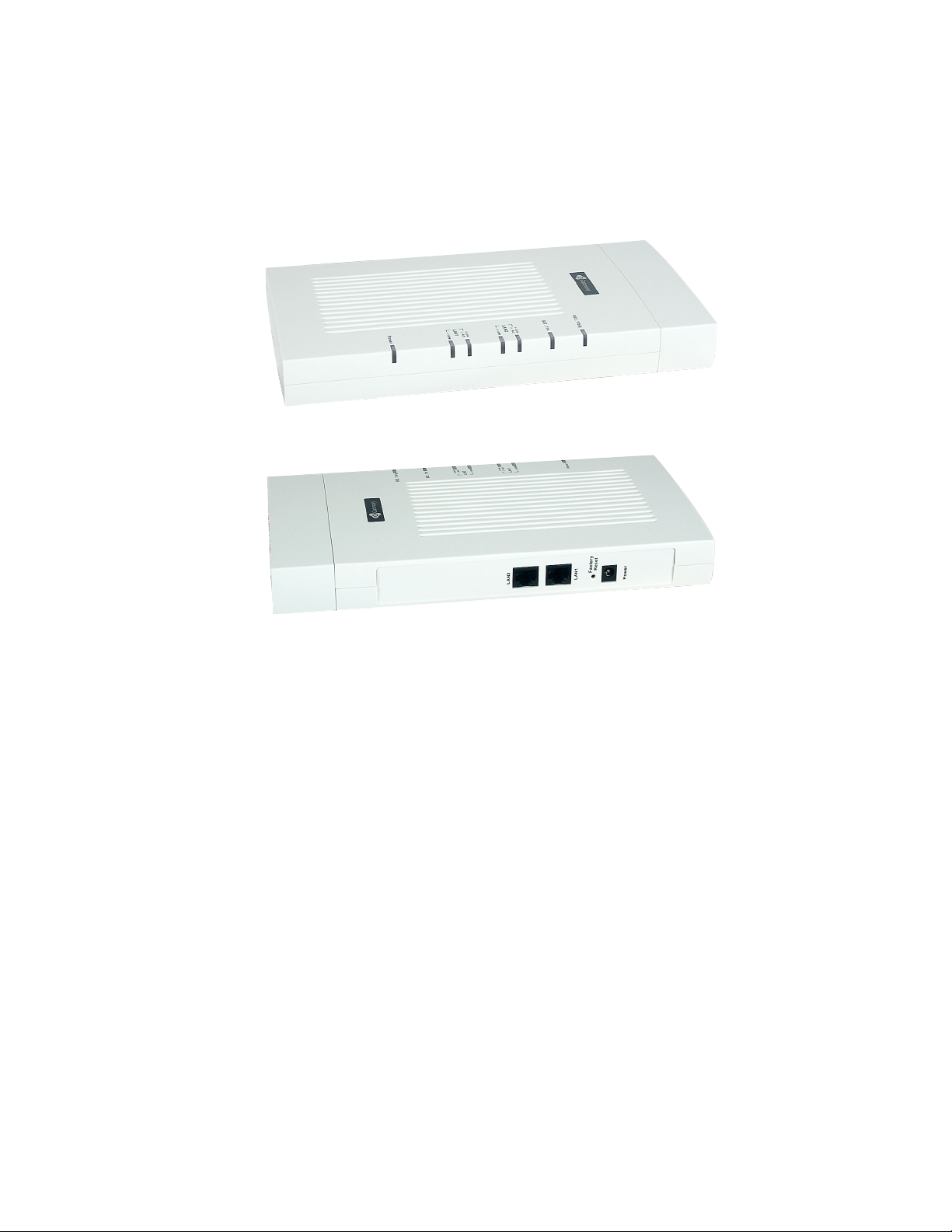
Unpacking the access point
Unpack the Access Point (AP) and familiarize yourself with its hardware ports, associated
cables, and accessories.
Access point hardware and ports
The access point includes:
■ Ethernet ports for connection to the Local Area Network (LAN) through Ethernet
network cable
■ Power port and power adapter
■ Power on/off switch
16
www.gateway.com
Page 22
Setting up the access point
For more information on the specifics of your access point, see ??????????????????
?????????????????????????????????.
What’s inside the access point?
An access point is a single-purpose computer designed to function as a wireless hub. Inside
the access point is a Wi-Fi radio system, a microprocessor, and sometimes a mini-PC card.
The access point boots from FlashROM that contains firmware with the configurable,
runtime features summarized in “Overview of the Gateway 7001 Series of self-managed
APs” on page 2.
As new features and enhancements become available, you can upgrade the firmware to
add new functionality and performance improvements to the access points that make up
your wireless network. (See “Upgrading the firmware” on page 129.)
Connecting the access point to network and power
The next step is to set up the network and power connections.
www.gateway.com
17
Page 23
Chapter 2: Quick Setup
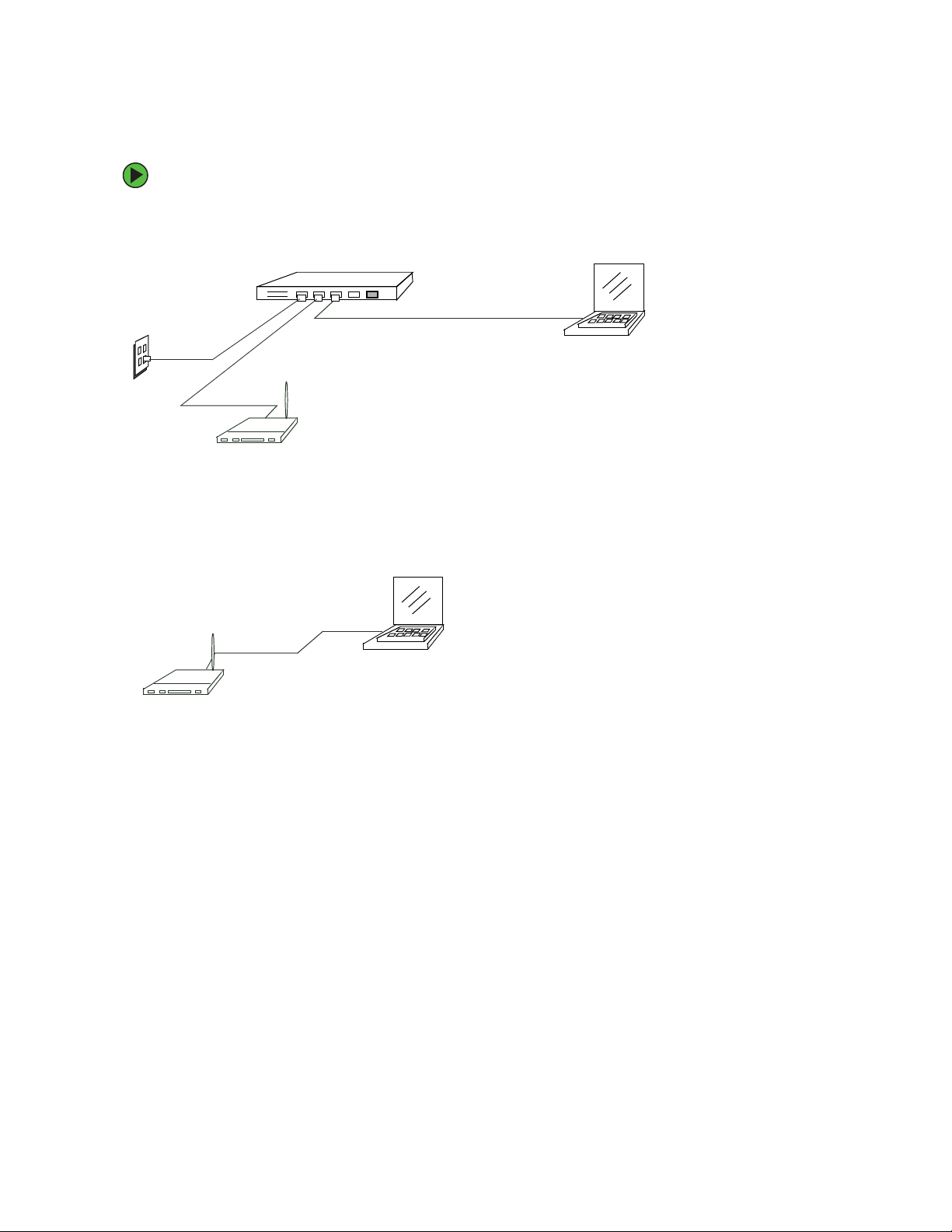
To set up the network and power connections:
1 Connect one end of an Ethernet cable to the network port on the access point and
the other end to the same hub where your computer is connected.
Hub
LAN
OR -
Connect one end of a crossover cable to the network port on the access point and
the other end of the cable to the Ethernet port on your computer.
Access point
N
A
L
o
t
B
U
H
Access point
b
u
H
o
t
P
A
Crossover cable
Admin computer to hub
Administrator computer
Administrator computer
(This computer must have an IP address on
the same subnet as the access point.)
18
www.gateway.com
Page 24

Setting up the access point
Important If you use a hub, the device you use must permit broadcast
signals from the access point to reach all other devices on
the network. A standard hub should work fine. Some
switches
broadcasts through. You may have to configure the switch
to allow directed broadcasts.
If for initial configuration you use a direct wired connection
(using a crossover cable) between the access point and
your computer, you will need to reconfigure the cabling for
subsequent startup and deployment of the access point so
that the access point is no longer connected directly to your
computer but instead is connected to the LAN (either using
a Hub or directly).
It is possible to detect access points on the network (using
Kickstart) with a wireless connection. However, we strongly
advise against using this method. In most environments
you may have no way of knowing whether you are actually
connecting to the intended AP and also because many of
the initial configuration changes required will cause you to
lose connectivity with the AP over a wireless connection.
, however, do not allow directed or subnet
2 Connect the power adapter to the power port on the back of the access point, then
plug the other end of the power cord into a power outlet (preferably, using a surge
protector).
Setting up connections for a guest network
The Gateway 7001 Series self-managed AP offers an out-of-the-box Guest Interface that
lets you configure an access point for controlled guest access to the network. The same
access point can function as a bridge for two different wireless networks: A secure Internal
LAN and a public Guest network. This can be done in one of two ways:
■ Physically, by connecting the two LAN ports on the access point to different networks
with two different cables, one to the internal LAN and the other to the public Guest
network.
■ Virtually, by defining two different Virtual LANs through the Administration UI.
Hardware connections for a guest VLAN
If you plan to configure a guest network using VLANs, do the following:
■ Connect eth0 to a VLAN-capable switch
■ Define VLANs on that switch
www.gateway.com
19
Page 25

Chapter 2: Quick Setup
Hardware connections for a physically separate guest network
If you plan to configure a physically separate guest network, you need to set up your
network connections differently at this point. The Gateway 7001 Series self-managed AP
ships with an extra network port to support configuration of a physically separate guest
network. Use both network ports on the access point to create two physical connections
to different networks:
■ Create a wired (Ethernet) connection from one of the network ports on the access point
to your internal LAN.
■ Create a second wired (Ethernet) connection from the other network port on the access
point to a separate network.
After you have the required physical connections set up, the rest of the configuration
process is accomplished through the Administration UI. For information on configuring
guest interface settings on the Administration UI, see “Advanced Configuration” on
page 63.
Turning on the access point
Press the power button on the Gateway 7001 Series self-managed AP, and wait for its
initialization process to complete. ??????????? is there a power button????? and what
happens when it is pushed (LEDs, lights???)
Running KickStart to find access points and assign IP
addresses
KickStart is an easy-to-use utility for discovering and identifying new Gateway access
points. KickStart scans the network looking for Gateway access points, and displays ID
details on those it finds.
20
www.gateway.com
Page 26

Setting up the access point
Important Keep in mind that KickStart (and the other Gateway
administration tools) recognizes and configures only
Gateway 7001 Series self-managed APs. KickStart will not
find or configure other kinds of access points or other
devices.
Run Kickstart only in the subnet of the “Internal” network
(SSID). Do not run Kickstart on the guest subnetwork.
Kickstart will find only those access points that have IP
addresses. IP addresses are dynamically assigned to APs
if you have a DHCP server running on the network. Keep
in mind that if you deploy the AP on a network with no
DHCP server, the default static IP address (192.168.1.1)
will be used.
Use caution with non-DHCP enabled networks: Do not
deploy more than one new AP on a non-DHCP network
unless you change the IP address list in the first DHCP
server, because they will use the same default static IP
addresses and conflict with each other. (For more
information, see “Understanding dynamic and static IP
addressing” on page 12 and “How does the access point
obtain an IP address at startup?” on page 12.)
Run the KickStart CD on a laptop or computer that is connected to the same network as
your access points and use it to step through the discovery process.
www.gateway.com
21
Page 27
Chapter 2: Quick Setup
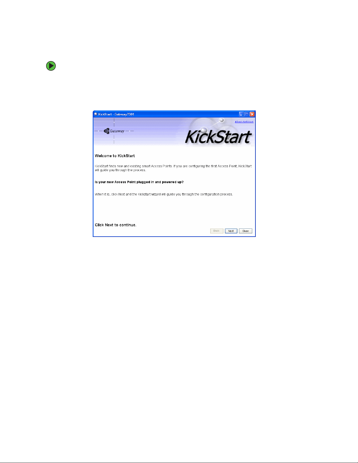
To run KickStart:
1 Insert the KickStart Wizard CD into the CD drive on your computer. If the KickStart
window is not displayed automatically, navigate to the CD drive and double-click the
Kickstart executable file to activate the KickStart utility on the CD. The KickStart
Welcom e screen is displayed.
22
www.gateway.com
Page 28

Setting up the access point
2 Click Next to search for access points. Wait for the search to complete, or until KickStart
has found your new access points.
Important If no access points are found, Kickstart indicates this and presents
some troubleshooting information about your LAN and power
connections. After you have checked hardware power and Ethernet
connections, you can click the Kickstart Back button to search again
for access points.
3 Review the list of access points found.
KickStart will detect the IP addresses of Gateway 7001 Series self-managed APs. Access
points are listed with their locations, Media Access Control (MAC) addresses, and IP
Addresses. If you are installing the first access point on a single-access-point network,
only one entry will be displayed on this screen.
Verify the MAC addresses shown here against the hardware labels for each access point.
This will be especially helpful later in providing or modifying the descriptive location
name for each access point. Click
Next to continue.
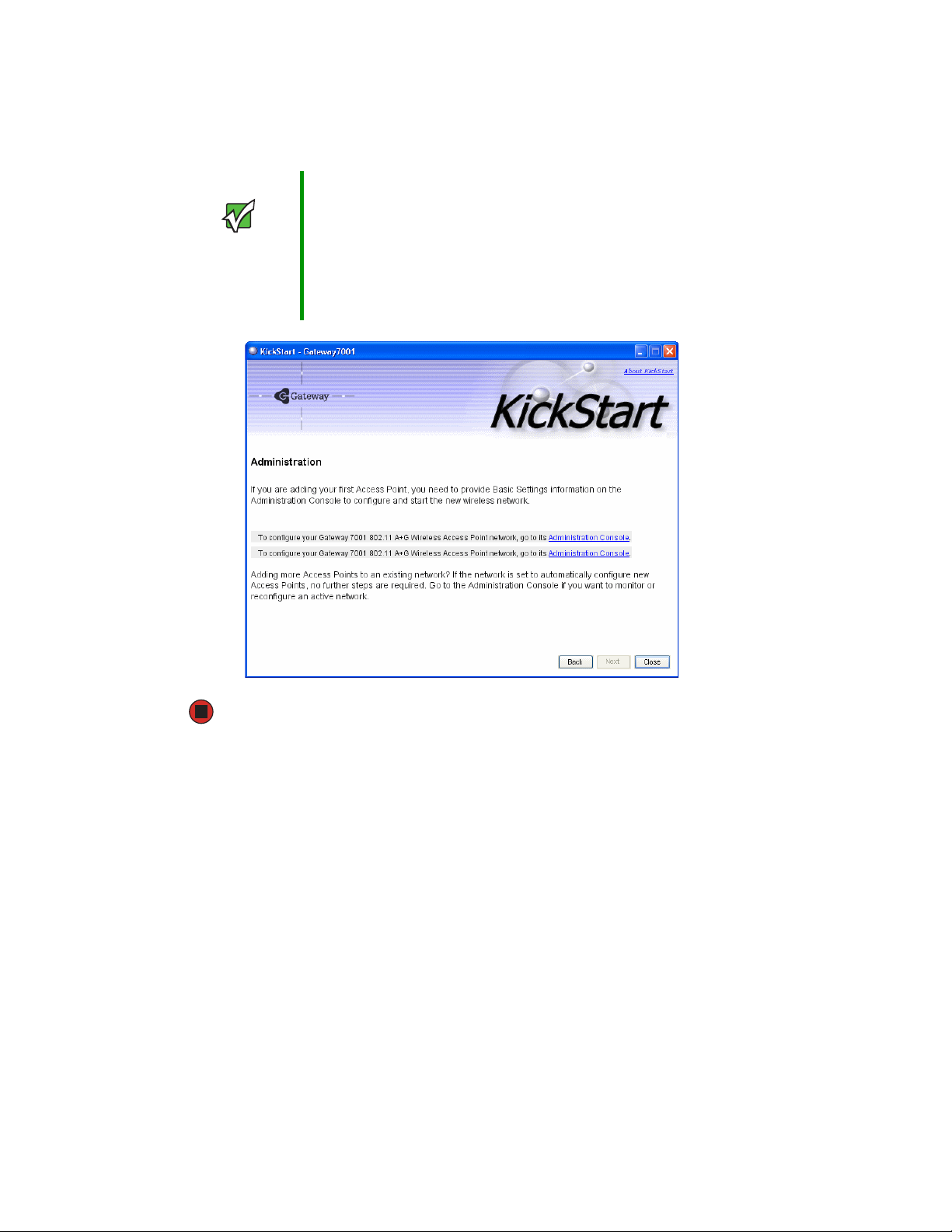
4 Go to the Access Point Administration Web pages by clicking the link provided on
the KickStart page (see “Logging on to the administration Web pages” on page 24).
www.gateway.com
23
Page 29
Chapter 2: Quick Setup
Important KickStart provides a link to the Administration Web pages
through the IP address of the first access point. The
Administration Web pages are a centralized management
tool that you can access through the IP address for any
access point in a cluster. After your other access points
are configured, you can also link to the Administration Web
pages by using the IP address for any of the other Gateway
access points in a URL (http://IPAddressOfAccessPoint).
Logging on to the administration Web pages
When you follow the link from KickStart to the Gateway 7001 Series self-managed AP
administration Web pages, you are prompted for a user name and password.
The defaults for user name and password are as follows.
24
www.gateway.com
Page 30
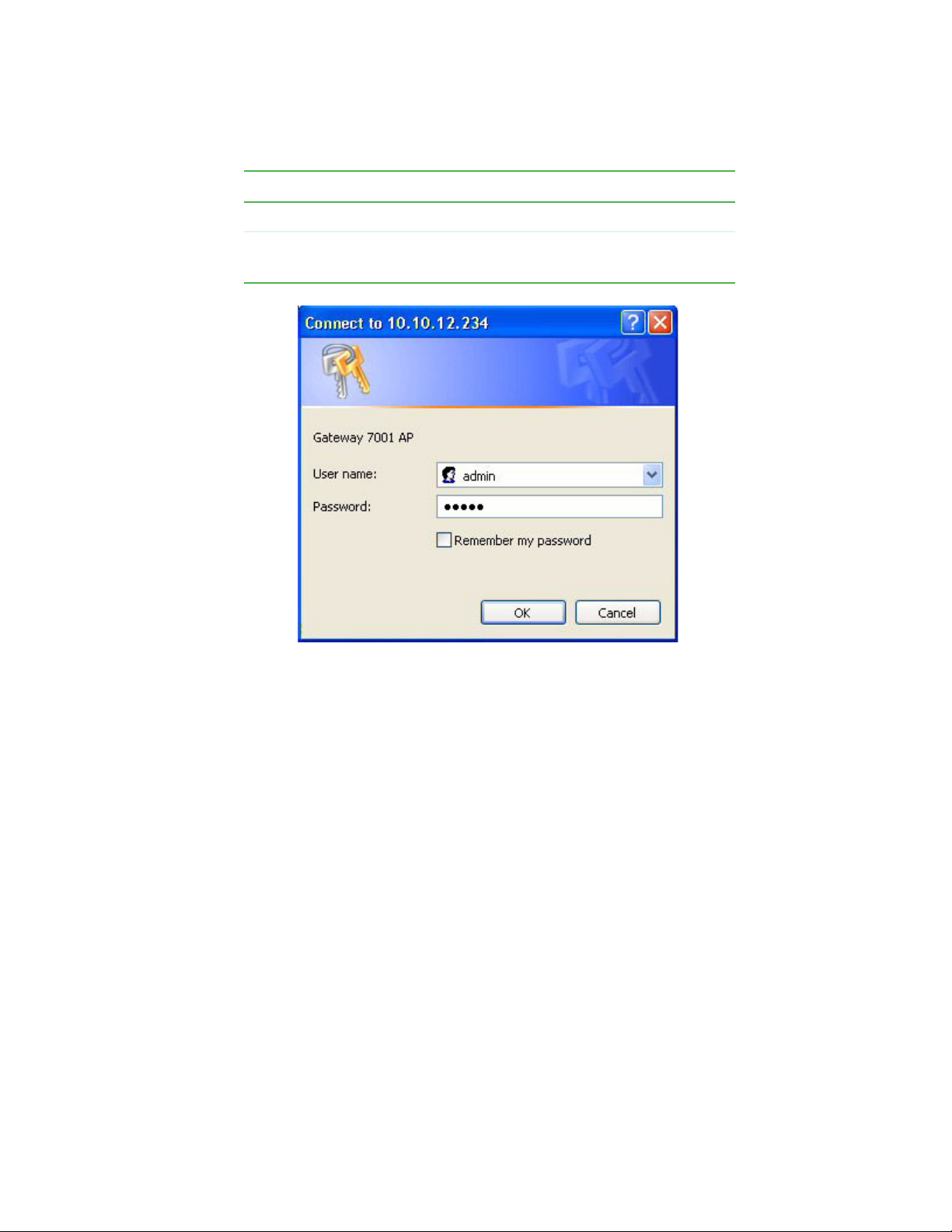
Field Default Setting
User name admin
Password admin
The user name is read-only. It cannot be modified.
Setting up the access point
Type the user name and password and click OK.
www.gateway.com
25
Page 31

Chapter 2: Quick Setup
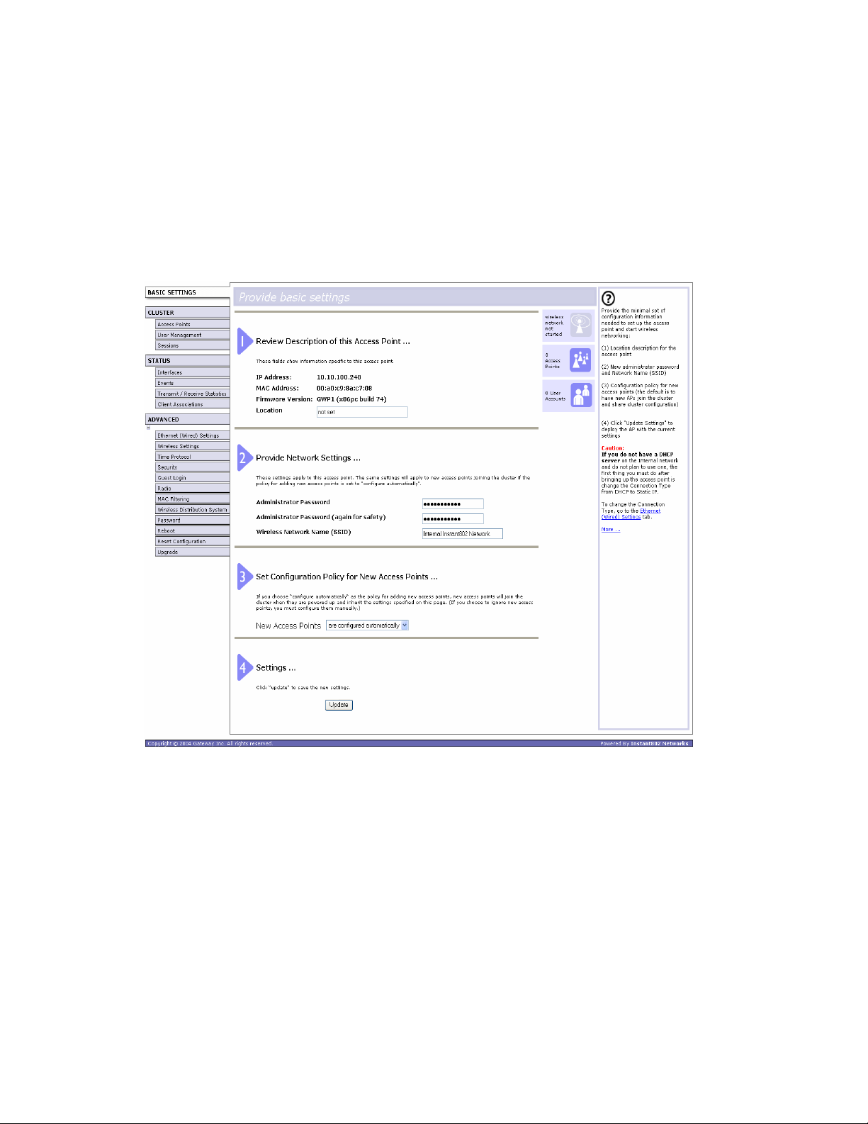
Viewing basic settings for Gateway 7001 Series self-managed access points
When you log in, the Basic Settings page for Gateway 7001 Series self-managed AP
administration is displayed. These are global settings for all access points that are members
of the cluster and, if automatic configuration is specified, for any new access points that
are added later.
26
www.gateway.com
Page 32

Setting up the access point
Configuring basic settings and starting the wireless
network
Provide a minimal set of configuration information by defining the basic settings for your
wireless network. These settings are all available on the Basic Settings page of the
Administration Web interface, and are categorized into steps 1-4 on the Web page.
To configure the basic settings:
1 Review the description of this access point and provide IP addressing information.
For more information, see “Reviewing and describing the access point” on page 31.
2 Provide a new administrator password for clustered access points. For more
information, see “Providing administrator password and wireless network name” on
page 32.
3 Set configuration policy for new access points.
Choose to configure new access points automatically (as new members of the cluster)
or ignore new access points.
If you set a configuration policy to configure new access points automatically, new
access points added to this network will join the cluster and be configured
automatically based on the settings you defined here. Updates to the network settings
on any cluster member will be shared with all other access points in the group.
If you chose to ignore new access points, then as you add new access points they will
run in standalone mode. In standalone mode, an access point does not share the
cluster configuration with other access points. Instead it must be configured manually.
You can always update the settings on a standalone access point to have it join the
cluster. You can also remove an access point from a cluster thereby switching it to
run in standalone mode.
For more information, see “Setting configuration policy for new access points” on
page 34.
4 Start wireless networking by clicking Update to activate the wireless network with these
new settings. For more information, see “Updating basic settings” on page 36.
Default configuration
If you follow the steps above and accept all the defaults, the access point will have the
default configuration described in “Default settings and supported administrator/client
platforms” on page 5.
www.gateway.com
27
Page 33

Chapter 2: Quick Setup
What’s next?
Make sure the access point is connected to the LAN and access some wireless clients. After
you have tested the basics of your wireless network, you can enable more security and
fine-tune by modifying advanced configuration features.
Make sure the access point is connected to the LAN
If you configured the access point and administrator computer by connecting both into
a network hub, then your access point is already connected to the LAN. The next step is
to test some wireless clients.
To test wireless clients:
1 If you configured the access point using a direct wired connection with a crossover
cable from your computer to the access point, disconnect the crossover cable from
your computer and the access point.
2 Connect a regular Ethernet cable from the access point to the LAN.
3 Connect your computer to the LAN either through Ethernet cable or wireless client
card.
Test LAN connectivity with wireless clients
Test the Gateway 7001 Series self-managed AP by trying to detect it and associate with it
from some wireless client devices. (See “Wireless client computers” on page 11 in the
PreLaunch Checklist: Default Settings and Supported Administrator/Client Platforms for
information on requirements for these clients.)
Secure and fine-tune the access point using advanced features
After you have the wireless network up and running and have tested against the access
point with some wireless clients, you can add in more layers of security, add users, configure
a guest interface, and fine-tune performance settings.
28
www.gateway.com
Page 34

Chapter 3
Configuring Basic Network
Settings
■ Navigating to basic settings
■ Reviewing and describing the access
point
■ Setting configuration policy for new
access points
■ Understanding basic settings for a
standalone access point
■ Understanding indicator icons
29
Page 35
Chapter 3: Configuring Basic Network Settings
Navigating to basic settings
To configure basic Network settings, click Network, then click Basic Settings.
If you use Kickstart to link to the Administration Web pages, the Basic Settings page is
displayed by default.
Fill in the boxes on the Basic Settings page as described in the following section.
30
www.gateway.com
Page 36
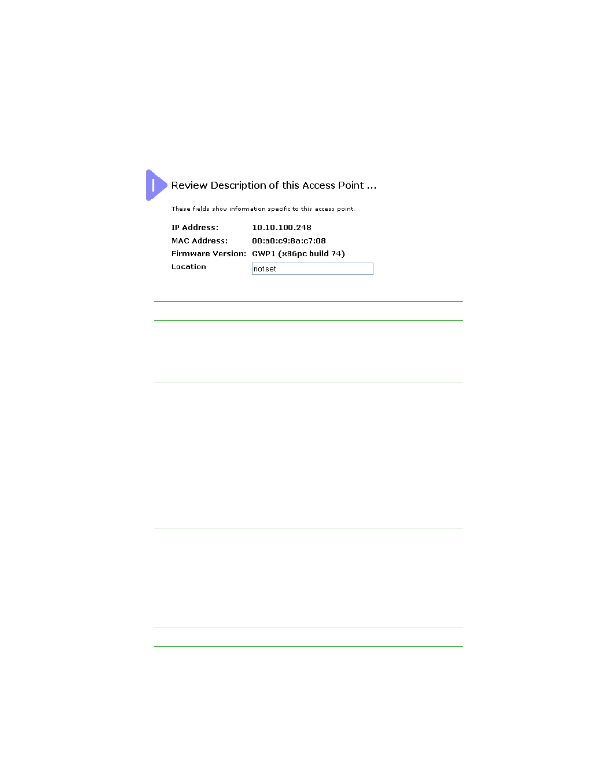
Reviewing and describing the access point
Reviewing and describing the access
point
Field Action
IP Address This box is not editable because the IP address is
already assigned (either through DHCP, or statically
through the Ethernet (Wired) settings as described in
“Configuring Guest interface Ethernet settings” on
page 69).
MAC Address A MAC address is a permanent, unique hardware
address for any device that represents an interface to the
network. The MAC address is assigned by the
manufacturer.
You cannot change the MAC address. It is provided here
for informational purposes as a unique identifier for an
interface.
The address shown here is the MAC address for the
bridge (br0). This is the address by which the AP is
known externally to other networks.
To see MAC addresses for guest and internal interfaces
on the AP, see the Status > Interfaces tab.
Firmware
Ver sion
Location Specify a location description for this access point.
Version information about the firmware currently installed
on the access point.
As new versions of the Gateway 7001 Series
self-managed AP firmware become available, you can
upgrade the firmware on your access points to take
advantages of new features and enhancements.
For instructions on how to upgrade the firmware, see
“Upgrading the firmware” on page 129.
www.gateway.com
31
Page 37
Chapter 3: Configuring Basic Network Settings
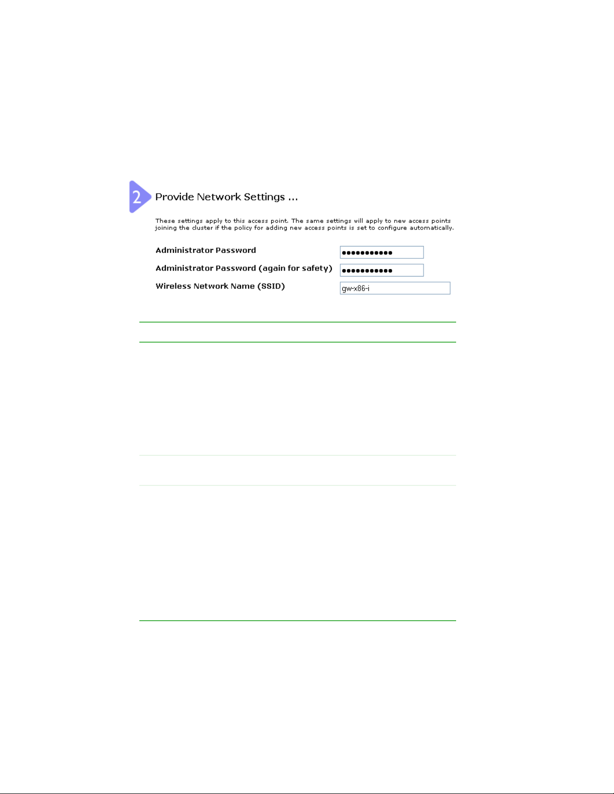
Providing administrator password and
wireless network name
Field Action
Administrator
Password
Administrator
Password (again)
Wireless
Network Name
(SSID)
Type a new administrator password. The characters you
enter will be displayed as “*” characters to prevent others
from seeing your password as you type.
The Administrator password must be an alphanumeric
strings of up to 32 characters. Do not use special
characters.
Note: As an immediate first step in securing your
wireless network, we recommend that you change the
administrator password from the default.
Re-type the new administrator password to confirm that
you typed it as intended.
Type a name for the wireless network as a character
string. This name will apply to all access points on this
network. As you add more access points, they will share
this SSID.
Service Set Identifier
The
string of up to 32 characters
Note: If you are connected as a wireless client to the
same AP that you are administering, resetting the SSID
will cause you to lose connectivity to the AP. You will need
to reconnect to the new SSID after you save this new
setting.
(SSID) is an alphanumeric
32
www.gateway.com
Page 38

Providing administrator password and wireless network name
Important The Gateway 7001 Series self-managed AP is not
designed for multiple, simultaneous configuration changes.
If you have a network that includes multiple access points,
and more than one administrator is logged on to the
Administration Web pages and making changes to the
configuration, all access points in the cluster will stay in
synch but there is no guarantee that all configuration
changes specified by multiple users will be applied.
www.gateway.com
33
Page 39

Chapter 3: Configuring Basic Network Settings
Setting configuration policy for new
access points
34
www.gateway.com
Page 40

Field Action
Setting configuration policy for new access points
New Access
Points
Choose the policy you want to put in effect for adding
New Access Points to the network.
• If you choose are configured automatically, then
when a new access points is added to the network it
cluster
automatically joins the existing
configuration is copied to the new access point, and no
manual configuration is required to deploy it.
• If you choose are ignored, new access points will not
join the cluster, but will be considered
need to configure standalone access points manually
through KickStart and the Administration Web pages
residing on the standalone access points. (To get to the
Web page for a standalone access point, use its IP
address in a URL as follows:
://IPAddressOfAccessPoint
http
Note: If you change the policy so that new access points
are ignored, then any new access points you add to the
network will not join the cluster. Existing clustered access
points will not be aware of these standalone APs.
Therefore, if you are viewing the Administration Web
pages through the IP address of a clustered access
point, the new standalone APs will not show up in the
list of access points on the Cluster > Access Points tab.
The only way to see a standalone AP is to browse to it
directly by using its IP address in the URL.
If you later change the policy back to the default so that
new access points “are configured automatically,” all
subsequent new APs will automatically join the cluster.
Standalone APs, however, will stay in standalone mode
until you explicitly add them to the cluster.
For information on how to add standalone APs to the
cluster, see “Adding an access point to a cluster” on
page 49.
.).
. The cluster
standalone
. You
www.gateway.com
35
Page 41

Chapter 3: Configuring Basic Network Settings
Updating basic settings
When you have reviewed the new configuration, click Update to apply the settings and
deploy the access points as a wireless network.
36
www.gateway.com
Page 42

Understanding basic settings for a standalone access point
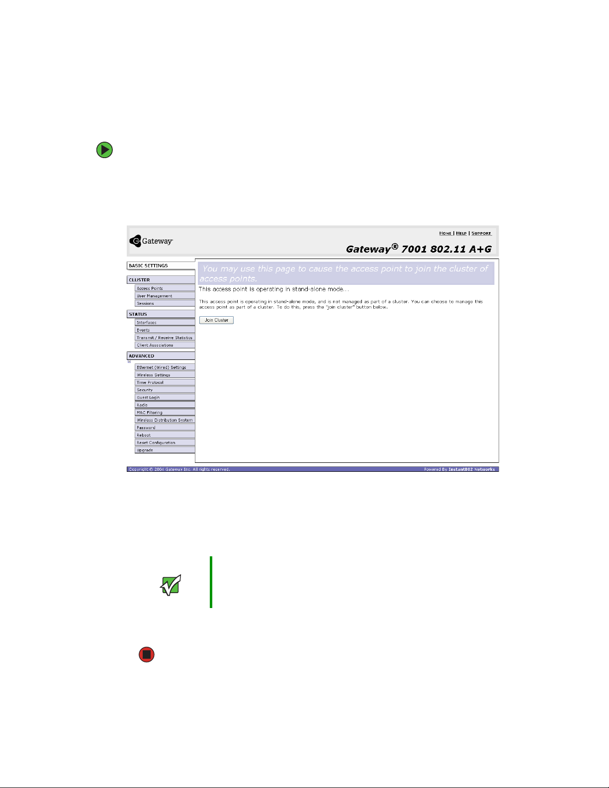
Understanding basic settings for a
standalone access point
The Basic Settings tab for a standalone access point indicates only that the current mode
is standalone and provides a button for adding the access point to a cluster (group). If
you click on any of the
standalone mode, you will be re-directed to the Basic Settings page because Cluster settings
do not apply to standalone APs.
For more information, see “Standalone mode” on page 44 and “Adding an access point
to a cluster” on page 49.
Cluster tabs on the Administration pages for an access point in
www.gateway.com
37
Page 43

Chapter 3: Configuring Basic Network Settings
Understanding indicator icons
All the network settings tabs on the Administration Web pages include visual indicator
icons showing current network activity
Icon Description
The clustering icon indicates whether the current access
point is “Clustered” or “Not Clustered” (that is,
standalone).
The number of access points available for service on this
network is indicated by the “Access Points” icon.
Then number of client user accounts created and
enabled on this network is indicated by the “User
Accounts” icon.
38
www.gateway.com
Page 44

Chapter 4
Managing Access Points and
Clusters
■ Navigating to access points management
■ Understanding clustering and access
points
■ Modifying the location description
■ Adding and removing an access point
■ Navigating to an AP by using its IP
address in a URL
39
Page 45

Chapter 4: Managing Access Points and Clusters
Introduction
The Gateway 7001 Series self-managed APs show current basic configuration settings for
clustered access points (location, IP address, MAC address, status, and availability) and
provide a way of navigating to the full configuration for specific APs if they are cluster
members.
Standalone access points (those which are not members of the cluster) do not show up
in this listing. To configure standalone access points, you must discover (through Kickstart)
or know the IP address of the access point and by using its IP address in a URL
(http://IPAddressOfAccessPoint).
Important The Gateway 7001 Series self-managed APs are not
designed for multiple, simultaneous configuration changes.
If you have a network that includes multiple access points,
and more than one administrator is logged on to the
Administration Web pages and making changes to the
configuration, all access points in the cluster will stay in
synch but there is no guarantee that all configuration
changes specified by multiple users will be applied.
40
www.gateway.com
Page 46

Navigating to access points management
Navigating to access points management
To view or edit information on access points in a cluster, click Cluster > Access Points on
the Administration Web page. The Manage access points in the cluster screen opens.
www.gateway.com
41
Page 47

Chapter 4: Managing Access Points and Clusters
Understanding clustering
A key feature of the Gateway 7001 Series self-managed AP is the ability to form a dynamic,
configuration-aware group (called a cluster) with other Gateway access points in a network
in the same subnet.
Access points can participate in a peer-to-peer cluster which makes it easier for you to
deploy, administer, and secure your wireless network. The cluster provides a single point
of administration and lets you view the deployment of access points as a single wireless
network rather than a series of separate wireless devices.
What is a cluster?
A cluster is a group of access points which are coordinated as a single group through
Gateway 7001 Series self-managed AP administration. You cannot create multiple clusters
on a single wireless network (SSID).
Only one cluster per wireless network is supported.
How many APs can a cluster support?
The Gateway 7001 Series self-managed AP can support up to eight access points in a cluster
at any one time. If a new AP is added to a network with a cluster that is already at full
capacity, the new AP is added in stand-alone mode. Note that when the cluster is full, extra
APs are added in stand-alone mode regardless of the configuration policy in effect for new
access points.
For related information, see “Cluster mode” on page 44, “Standalone mode” on page 44,
and “Setting configuration policy for new access points” on page 34.
What kinds of APs can cluster together?
A Gateway 7001 Series self-managed AP can form a cluster with itself (a “cluster of one”)
and with other Gateway 7001 Series self-managed APs that share some basic characteristics.
In order to be members of the same cluster, access points must be Gateway 7001 Series
self-managed APs:
■ Of the same radio configuration (all dual-band APs or all single-band APs)
■ On the same LAN
A dual-band and a single-band AP cannot be members of the same cluster. Therefore, a
Gateway 7001 802.11 A+G Wireless Access Point (dual-band) cannot cluster with a Gateway
7001 802.11 G Wireless Access Point (single-band). Also, Gateway 7001 Series self-managed
APs will not cluster with non Gateway APs.
42
www.gateway.com
Page 48

Understanding clustering
Having a mix of APs on the network does not adversely affect Gateway 7001 Series
self-managed AP clustering in any way, however it is helpful to understand the clustering
behavior for administration purposes:
■ Gateway 7001 Series self-managed APs of the same model will form a cluster. The
dual-band APs will form one cluster and the single-band APs will form another cluster.
■ Non-Gateway APs will not join Gateway clusters. They should be administered as usual
through their associated Administration tools.
Which settings are shared in the cluster configuration
and which are not?
Most configuration settings defined through the Gateway 7001 Series self-managed AP
Administration Web pages will be propagated to cluster members as a part of the cluster
configuration.
Settings shared in the cluster configuration
The cluster configuration includes:
■ Network name (SSID)
■ Administrator password
■ Configuration policy
■ User accounts and authentication
■ Wireless interface settings
■ Radio settings
■ QoS queue parameters
■ MAC address filtering.
Settings not shared by the cluster
The few exceptions (settings not shared among clustered access points) are the following
most of which, by nature, must be unique:
■ IP addresses
■ MAC addresses
■ Location descriptions
■ WDS bridges
■ Security settings
■ Ethernet (Wired) Settings, including enabling or disabling Guest access
■ Guest interface configuration
www.gateway.com
43
Page 49

Chapter 4: Managing Access Points and Clusters
Settings that are not shared must be configured individually on the Administration pages
for each access point. To get to the Administration pages for an access point that is a
member of the current cluster, click on its IP Address link on the
page of the current AP.
Cluster > Access Points
Cluster mode
When an access point is a cluster member, it is considered to be in cluster mode. You define
whether you want new access points to join the cluster or not through the configuration
policy you set in Basic Settings. (See “Setting configuration policy for new access points”
on page 34.) You can re-set an access point in cluster mode to standalone mode. (See
“Removing an access point from the cluster” on page 48.)
Important When the cluster is full (eight APs is the limit), extra APs
are added in
configuration policy in effect for new access points. See
“How many APs can a cluster support?” on page 42.
Gateway 7001 Series self-managed APs of different
models form separate clusters. See “What kinds of APs
can cluster together?” on page 42.
stand-alone mode
regardless of the
Standalone mode
Gateway 7001 Series self-managed APs can be configured in standalone mode. In
standalone mode, an access point is not a member of the cluster and does not share the
cluster configuration, but rather requires manual configuration that is not shared with
other access points. (See “Setting configuration policy for new access points” on page 34
and “Removing an access point from the cluster” on page 48.)
Standalone access points are not listed on the
Administration UI.
You need to know the IP address for a standalone access point in order to configure and
manage it directly. (See “Navigating to an AP by using its IP address in a URL” on page 50.)
The Basic Settings tab for a standalone access point indicates only that the current mode
is standalone and provides a button for adding the access point to a cluster (group). If
you click on any of the Cluster tabs on the Administration pages for an access point in
standalone mode, you will be redirected to the Basic Settings page because Cluster settings
do not apply to stand-alone APs.
Important When the cluster is full (eight APs is the limit), extra APs
are added in
configuration policy in effect for new access points. See
“How many APs can a cluster support?” on page 42.
stand-alone mode
Cluster > Access Points tab in the
regardless of the
44
www.gateway.com
Page 50

Understanding clustering
You can re-enable cluster mode on a standalone access point. (See “Adding an access point
to a cluster” on page 49.)
Cluster formation
A cluster is formed when the first Gateway 7001 Series self-managed AP is configured. (See
“Quick Setup” on page 15 and “Configuring Basic Network Settings” on page 29.)
If a cluster configuration policy is in place when a new access point is deployed, it attempts
to rendezvous with an existing cluster.
If it is unable to locate a cluster, then it establishes a new cluster on its own.
If it locates a cluster but is rejected because the cluster is full, or the clustering policy is
to ignore new access points, then the access point will deploy in standalone mode.
Cluster size and membership
The upper limit of a cluster is eight access points. The Network Web administration page
provides a real-time, visual indicator of the number of access points in the current cluster
and warns when the cluster has reached capacity. (See “Configuring basic settings and
starting the wireless network” on page 27.)
If a cluster is present but is already full, new access points will deploy in standalone mode.
Intra-cluster security
To make sure that the security of the cluster as a whole is equivalent to the security of a
single access point, communication of certain data between access points in a cluster is
done using Secure Sockets Layer (typically referred to as SSL) with private key encryption.
Both the cluster configuration file and the user database are transmitted among access
points using SSL.
www.gateway.com
45
Page 51

Chapter 4: Managing Access Points and Clusters
Auto-Synch of Cluster Configuration
If you are making changes to the AP configuration that require a relatively large amount
of processing (such as adding several new users), you may encounter a synchronization
progress bar after clicking
indicates that the system is busy performing an auto-synch of the updated configuration
to all APs in the cluster. The Administration Web pages are not editable during the
auto-synch.
Note that auto-synchronization always occurs during configuration updates that affect the
cluster, but the processing time is usually negligible. The auto-synch progress bar is
displayed only for longer-than-usual wait times.
Update on any of the Administration pages. The progress bar
46
www.gateway.com
Page 52

Understanding access point settings
Understanding access point settings
The Access Points tab on the Administration Web page provides information about all
access points on the wireless network.
From this tab, you can view location descriptions, IP addresses, enable (activate) or disable
(deactivate) clustered access points, and remove access points from the cluster. You can
also modify the location description for an access point.
The IP address links provide a way to navigate to configuration settings and data on an
access point.
Navigating to a specific access point can be particularly useful for access points running
in standalone mode.
The following table describes the access point settings and information display in detail.
Field Description
Location Description of where the access point is physically located.
MAC Address Media Access Control (MAC) address of the access point.
MAC address
A
that represents an interface to the network. The MAC address is assigned
by the manufacturer. You cannot change the MAC address. It is provided
here for informational purposes as a unique identifier for the access point.
Even if an access point is configured for multiple BSSIDs and has multiple
MAC addresses, only one of its MAC addresses will be shown in this list.
is a permanent, unique hardware address for any device
IP Address Specifies the IP address for the access point. Each IP address is a link to
the Administration Web pages for that access point. You can use the links
to navigate to the Administration Web pages for a specific access point.
This is useful for viewing data on a specific access point to make sure a
cluster member is picking up cluster configuration changes, to configure
advanced settings on a particular access point, or to switch a standalone
access point to cluster mode.
www.gateway.com
47
Page 53

Chapter 4: Managing Access Points and Clusters
Working with access points in a cluster
Modifying the location description
To make modifications to the location description:
1 Click Basic Settings on the Administration Web page.
2 Update the location description in section 1 under “Review Description of this Access
Point.”
3 Click Update to apply the changes.
Removing an access point from the cluster
To remove an access point from the cluster:
1 Click Cluster > Access Points on the Administration Web page. The Manage access points
in the cluster screen opens.
2 Click the box next to the access point you want to disable.
3 Click Remove from Cluster.
The change will be reflected under Status for that access point and it will now show
as standalone (instead of cluster).
48
www.gateway.com
Page 54
Working with access points in a cluster
Adding an access point to a cluster
To add an access point that is currently in standalone mode back into a cluster:
1 Go to the Administration Web pages for the standalone access point. (See “Navigating
to an AP by using its IP address in a URL” on page 50.)
The Administration Web page for the standalone access point is displayed.
2 Click the Basic Settings tab in the Administration pages for the standalone access
point.
The
Basic Settings tab for a standalone access point indicates that the current mode
is standalone and provides a button for adding the access point to a cluster (group).
Important When the cluster is full (eight APs is the limit), extra APs
are added in
configuration policy in effect for new access points. See
“How many APs can a cluster support?” on page 42.
stand-alone mode
regardless of the
3 Click Join Cluster. The access point is now a cluster member. Its Status (Mode) on the
Cluster > Access Points tab now indicates cluster instead of standalone.
www.gateway.com
49
Page 55

Chapter 4: Managing Access Points and Clusters
Navigating to information for a specific
AP and managing standalone APs
In general, Gateway 7001 Series self-managed APs are designed for central management
of clustered access points. For access points in a cluster, all access points in the cluster
reflect the same configuration. In this case, it does not matter which access point you
actually connect to for administration.
There may be situations, however, when you want to view or manage information on a
particular access point. For example, you might want to check status information such as
client associations or events for an access point. Or you might want to configure and
manage features on an access point that is running in standalone mode. In these cases,
you can navigate to the Administration Web interface for individual access points by
clicking the IP address links on the Access Points tab.
All clustered access points are shown on the Cluster > Access Points page. To navigate to
clustered access points, you click on the IP address for a specific cluster member shown
in the list.
Navigating to an AP by using its IP address in a URL
You can also link to the Administration Web pages of a specific access point, by typing
the IP address for that access point as a URL directly into a Web browser address bar in
the following form:
http://IPAddressOfAccessPoint
(where IPAddressOfAccessPoint is the address of the particular access point you want
to monitor or configure).
For standalone access points, this is the only way to navigate to their configuration
information. If you do not know the IP address for a standalone access point, use Kickstart
to find all APs on the network and you should be able to derive which ones are standalone
by comparing KickStart findings with access points listed on the
tab. The APs that Kickstart finds that are not shown on the this tab are probably standalone
APs. (For more information on using Kickstart, see “Running KickStart to find access points
and assign IP addresses” on page 20.)
Cluster > Access Points
50
www.gateway.com
Page 56

Chapter 5
Managing User Accounts
■ Navigating to user management for
clustered access points
■ Viewing and changing user accounts
■ Adding a user
■ Editing a user accountt
■ Enabling and disabling user accounts
■ Removing a user
51
Page 57

Chapter 5: Managing User Accounts
Introduction
The Gateway 7001 Series self-managed APs include user management capabilities for
controlling client access to access points.
User management and authentication must always be used in conjunction with the
following two security modes, which require use of a RADIUS server for user authentication
and management.
■ IEEE 802.1x mode (see “IEEE 802.1x” on page 89 in Configuring network security)
■ WPA with RADIUS mode (see “WPA with RADIUS” on page 91 in Configuring network
security)
You have the option of using either the internal RADIUS server embedded in the Gateway
7001 Series self-managed AP or an external RADIUS server that you provide. If you use
the Gateway 7001 Series self-managed AP embedded RADIUS server, use this
Administration Web page on the access point to set up and manage user accounts. If you
are using an external RADIUS server, you need to set up and manage user accounts on
the Administrative interface for that server.
On the User Management page, you can create, edit, remove, and view client user accounts.
Each user account consists of a user name and password. The set of users specified here
represent approved clients that can log in and use one or more access points to access local
and possibly external networks via your wireless network.
52
Important Users specified here are clients of the Gateway access
point(s) who use the APs as a connectivity hub, not
administrators of the wireless network. Only those with the
administrator user name and password and knowledge of
the administration URL can log in as an administrator and
view or modify configuration settings.
www.gateway.com
Page 58

Navigating to user management for clustered access points
Navigating to user management for
clustered access points
To set up or modify user accounts, click Cluster > User Management on the Administration
Web page. T h e Manage user accounts screen opens.
www.gateway.com
53
Page 59

Chapter 5: Managing User Accounts
Viewing and changing user accounts
Viewing user accounts
User accounts are shown at the top of the Manage user accounts screen under User Accounts.
User name, real name and status (enabled or disabled) are shown. You can make
modifications to an existing user account by first selecting the checkbox next to a user
name then choosing an action. (See “Editing a user account” on page 55)
Adding a user
To create a new user:
1 On the Manage user accounts screen, under Add a User, provide information in the
following boxes.
Field Description
User name Provide a user name.
User names are alphanumeric strings of up to 256
characters. Do not use special characters.
Real Name For information purposes, provide the user’s full name.
There is a 256 character limit on real names.
Password Specify a password for this user.
Passwords are alphanumeric strings of up to 256
characters. Do not use special characters.
2 When you have filled in the boxes, click Add Account to add the account.
The new user is then displayed in User Accounts. The user account is enabled by
default when you first create it.
Important A limit of 100 user accounts per access point is imposed
by the Administration user interface. Network usage may
impose a more practical limit, depending on the demand
from each user.
54
www.gateway.com
Page 60

Viewing and changing user accounts
Editing a user account
After you have created a user account, it is displayed under User Accounts at the top of
the User Management Web page. To make modifications to an existing user account, first
click the checkbox next to the user name so that a checkmark is displayed in the box.
Then, choose an action such as
Edit, Enable, Disable, or Remove.
Enabling and disabling user accounts
A user account must be enabled for the user to log on as a client and use the access point.
You ca n enable or disable any user account. With this feature, you can maintain a set of
user accounts and authorize or prevent users from accessing the network without having
to remove or re-create accounts. This is convenient in situations where users have an
occasional need to access the network. For example, contractors who do work for your
company on an intermittent but regular basis might need network access for 3 months
at a time, then be off for 3 months, and back on for another assignment. You can enable
and disable these user accounts as needed, and control access as appropriate.
To enable a user account:
■ On the User Management Web page, under User Accounts, click the box next to the user
name, then click
A user with an account that is enabled can log on to the wireless access points in
your network as a client.
Enable.
www.gateway.com
55
Page 61

Chapter 5: Managing User Accounts
To disable a user account:
■ On the User Management Web page, under User Accounts, click the box next to the user
name, then click
Disable.
A user with an account that is disabled cannot log on to the wireless access points
in your network as a client. However, the user remains in the database and can be
enabled later as needed.
To remove a user account:
■ On the User Management Web page, under User Accounts, click the box next to the user
name, then click
If you think you might want to add this user back in at a later date, you might consider
disabling the user rather than removing the account altogether.
Remove.
56
www.gateway.com
Page 62

Chapter 6
Session Monitoring
■ Navigating to session monitoring
■ Understanding session monitoring
information
■ Viewing session information for access
points
■ Sorting session information
■ Refreshing session information
57
Page 63

Chapter 6: Session Monitoring
Navigating to session monitoring
To view session monitoring information, click Cluster > Sessions on the Administration
Web page. T h e Monitor active client station sessions page opens.
58
www.gateway.com
Page 64

Understanding session monitoring information
Understanding session monitoring
information
The Monitor active client station sessions page shows the stations associated with access points
in the cluster.
A session in this context is the period of time in which a user on a client device (station)
with a unique MAC address maintains a connection with the wireless network. The session
begins when the client logs on to the network, and the session ends when the client either
logs off intentionally or loses the connection for some other reason.
Important A session is not the same as an association, which
describes a client connection to a particular access point.
A client network connection can shift from one clustered
AP to another within the context of the same session. A
client station can roam between APs and maintain the
session.
Details about the session information shown is described in the following table.
Field Description
User Name Indicates the client user name.
AP Location Indicates the location of the access point.
This is derived from the location description specified on the Basic Settings
tab.
User MAC
Address
Idle Time Indicates the amount of time this station has remained inactive.
Data Rate The speed at which this access point is transferring data to the specified
Indicates the MAC address of the user’s client device (station).
A MAC address is a hardware address that uniquely identifies each node
of a network.
A station is considered to be “idle” when it is not receiving or transmitting
data.
client.
The data transmission rate is measured in megabits per second (Mbps).
This value should fall within the range of the advertised rate set for the
IEEE 802.1x mode in use on the access point. For example, 6 to 54Mbps
for 802.11a.
www.gateway.com
59
Page 65

Chapter 6: Session Monitoring
Field Description
Signal Indicates the strength of the radio frequency (RF) signal the client receives
from the access point.
The measure used for this is an IEEE 802.1x value known as
Signal Strength Indication
RSSI is determined by a an IEEE 802.1x mechanism implemented on the
network interface card (NIC) of the client station.
Utilization Utilization rate for this station.
For example, if the station is “active” (transmitting and receiving data) 90%
of the time and inactive 10% of the time, its “utilization rate” is 90%.
RxAve Indicates number of total packets received by the client during the current
session.
TxAve Indicates number of total packets transmitted to the client during this
session.
Error Rate Indicates the percentage of time frames are dropped during transmission
on this access point.
Received
(RSSI), and will be a value between 0 and 100.
60
www.gateway.com
Page 66

Viewing session information for access points
Viewing session information for access
points
You can view session information for all access points on the network at the same time,
or set the display to show session information for a specified access point chosen from
the list at the top of the screen.
To view information on all access points, select the
top of the page.
To view session information on a particular access point, select the
point
option and choose the access point name from the list.
Show all access points option at the
Show only this access
Sorting session information
To order (sort) the information shown in the tables by a particular indicator, click on the
column label by which you want to order things. For example, if you want to see the table
rows ordered by utilization rate, click
rate.
Utilization. The entries will be sorted by utilization
Refreshing session information
You can set the time in seconds for this screen to automatically update with live
information. You can also force an update of the information displayed by clicking
Refresh.
www.gateway.com
61
Page 67

Chapter 6: Session Monitoring
62
www.gateway.com
Page 68

Chapter 7
Advanced Configuration
■ Configuring an Ethernet (wired)
interface
■ Configuring a wireless interface
■ Configuring network security
■ Configuring radio settings
63
Page 69

Chapter 7: Advanced Configuration
Configuring an Ethernet (wired) interface
Ethernet (Wired) Settings describe the configuration of your Ethernet local area network
(LAN)
Caution The Ethernet Settings, including Guest Access, are not
shared across the cluster. These settings must be
configured individually on the Administration pages for
each access point. To get to the Administration pages for
an access point that is a member of the current cluster,
click on its IP Address link on the Cluster > Access Points
page of the current AP. For more information about which
settings are shared by the cluster and which are not, see
“Which settings are shared in the cluster configuration and
which are not?” on page 43.
64
www.gateway.com
Page 70
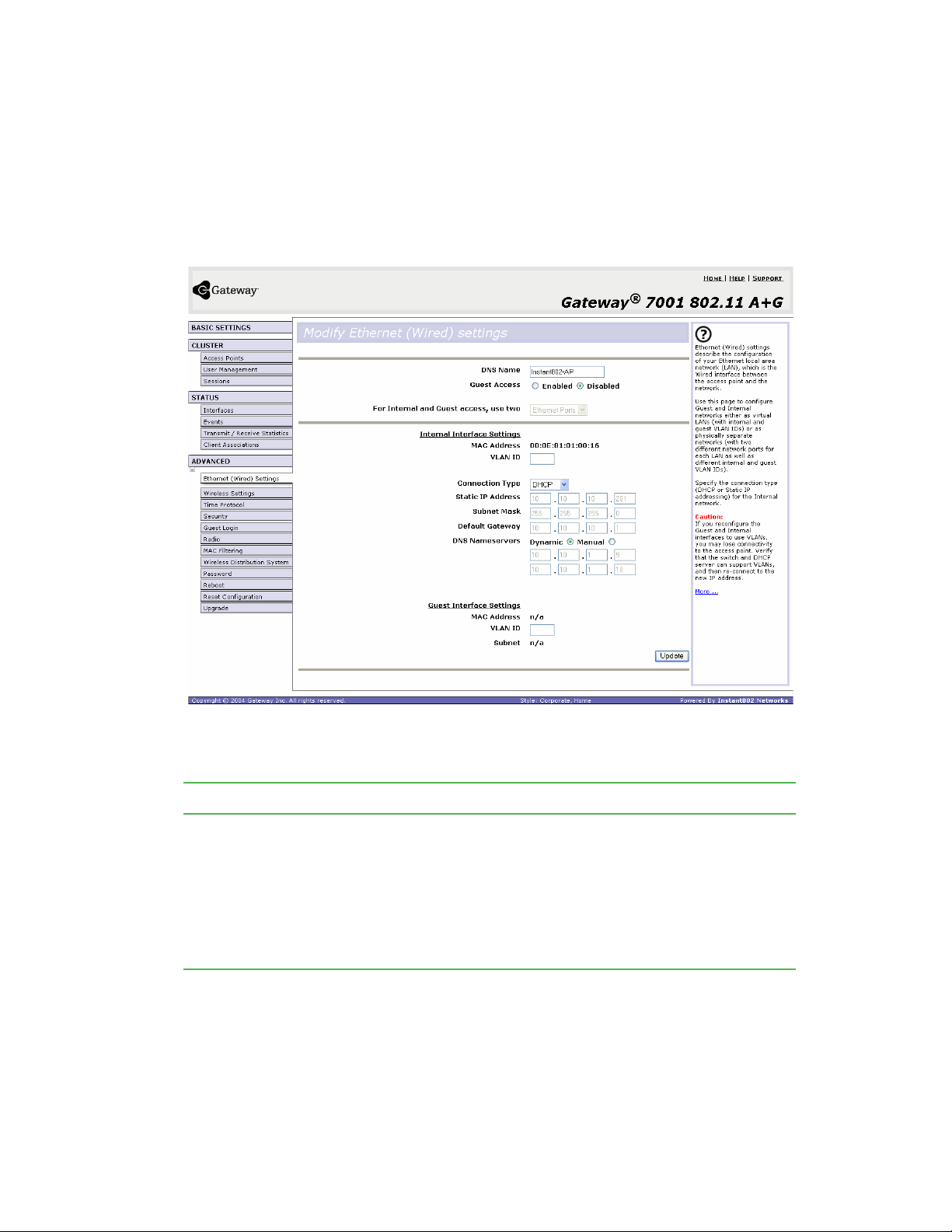
Configuring an Ethernet (wired) interface
Navigating to Ethernet (wired) settings
To set the wired address for an access point, Advanced > Ethernet (Wired) Settings on the
Administration Web page, and update the boxes as described in the following section.
Setting the DNS name
Field Description
DNS Name Type a DNS name for the access point in the text box.
This is the host name. It may be provided by your ISP or network
administrator, or you can provide your own.
The rules for system names are:
• This name can be up to 20 characters long.
• Only letters, numbers and dashes are allowed.
• The name must start with a letter and end with either a letter or a number.
www.gateway.com
65
Page 71

Chapter 7: Advanced Configuration
Enabling or Disabling Guest Access
You can provide controlled guest access over an isolated network and a secure internal
LAN on the same Gateway 7001 Series self-managed AP.
Configuring an internal LAN and a guest network
A Local Area Network (LAN) is a communications network covering a limited area, for
example, one floor of a building. A LAN connects multiple computers and other network
devices like storage and printers.
Ethernet is the most common technology implementing a LAN. Wi-Fi (IEEE) is another
popular LAN technology.
The Gateway 7001 Series self-managed AP lets you configure two different LANs on the
same access point: one for a secure internal LAN and another for a public guest network
with no security and little or no access to internal resources. To configure these networks,
you need to provide both Wireless and Ethernet (Wired) settings.
Information on how to configure the Ethernet (Wired) settings is provided in the next
sections.
(For information on how to configure the Wireless settings, see “Configuring a wireless
interface” on page 70. For an overview of how to set up the guest interface, see “Advanced
Configuration” on page 63.)
Enabling or Disabling Guest Access
The Gateway 7001 Series self-managed AP ships with the Guest Access feature disabled by
default. If you want to provide guest access on your AP, enable Guest access on the Ethernet
(Wired) Settings tab.
Field Description
Guest Access By default, the Gateway® 7001 AP ships with Guest Access disabled.
• To enable Guest Access, click Enabled.
• To disable Guest Access, click Disabled.
Specifying a physical or virtual Guest network
If you enable Guest Access, you must choose a method of representing both an internal
and guest Network on this access point. There are two ways of doing this:
■ Physically, by connecting the two LAN ports on the access point to different networks
with two different cables, one to the internal LAN and another to a guest network.
■ Virtually, by connecting the LAN port on the access point to a tagged port on a VLAN
capable switch then defining two different virtual LANs on this Administration page.
(For more information, see “Advanced Configuration” on page 63).
66
www.gateway.com
Page 72

Configuring an Ethernet (wired) interface
Choose either physically separate or virtually separate internal and guest LANs as described
in the following section.
Field Description
For Internal and
Guest access,
use two
Caution If you reconfigure the Guest and Internal interfaces to use
Specify either a physically or virtually separate guest network on this access
point:
■
If you connected this access point to two separate networks for a “physically
secure” solution, then choose Ethernet Ports from the list. (Choosing
“Ethernet Ports” here will disable the “VLAN” settings.)
■
If the access point is using only one physical connection to your internal
LAN (extra port is not in use), then choose VLANs from the list. (This will
enable the “VLAN” settings.)
VLANs, you may lose connectivity to the access point.
First, be sure to verify that the switch and DHCP server
you are using can support VLANs per the IEEE 802.1Q
standard. After configuring the VLAN on the
Ethernet (Wired) Settings
Ethernet cable on the switch to the tagged packet (VLAN)
port. Then, re-connect throughthrough the Administration
Web pages to the new IP address. (If necessary, check
with the infrastructure support administrator regarding the
VLAN and DHCP configurations.)
page, physically reconnect the
Advanced >
Configuring Internal interface Ethernet settings
To configure Ethernet (Wired) settings for the internal LAN, fill in the boxes as described
in the following table.
Field Description
MAC Address Shows the MAC address for the internal interface for this access point. This
is a read only box that you cannot change.
VLAN ID If you choose to configure internal and guest networks by “VLANs”, this box
will be enabled.
Provide a number between 1 and 4094 for the internal VLAN.
This will cause the access point to send DHCP requests with the VLAN tag.
The switch and the DHCP server must support VLAN IEEE 802.1Q frames.
The access point must be able to reach the DHCP server.
Check with the Administrator regarding the VLAN and DHCP configurations.
www.gateway.com
67
Page 73

Chapter 7: Advanced Configuration
Field Description
Connection Type You can select “DHCP Client” or “Static IP”.
Dynamic Host Configuration Protocol
The
how a centralized server can provide network configuration information to
clients. A DHCP server “offers” a “lease” to the client system. The information
supplied includes the client's IP addresses and net mask plus the address
of its DNS servers and gateway.
Static IP indicates that all network settings are provided manually. You must
provide the IP address for the Gateway 7001 Series self-managed Access
Point, its subnet mask, the IP address of the default gateway, and the IP
address of at least one DNS nameserver.
If you select “DHCP Client”, the Gateway 7001 Series self-managed AP will
acquire its IP Address, subnet mask, and DNS and gateway information from
the DHCP Servers.
Otherwise, if you select “Static IP”, fill in the items described in “Static IP
Settings.”
IMPORTANT: If you do not have a DHCP server on the Internal network and
do not plan to use one, the first thing you must do after bringing up the AP
is change the Connection Type from DHCP to Static IP. When you change
the Connection Type to Static IP, you can either assign a new Static IP
Address to the AP or continue using the default address. We recommend
assigning a new address so that if later you bring up another Gateway 7001
Series self-managed AP on the same network, the IP addresses for the two
APs will be unique.
If you need to recover the default Static IP address, you can do so by resetting
the AP to the factory defaults as described in “Resetting the configuration”
on page 128.
(DHCP) is a protocol specifying
Static IP Address If you chose “Static IP” as the Connection Type, these boxes will be enabled.
Type the Static IP Address in the text boxes.
Subnet Mask Type the Subnet Mask in the text boxes. You must obtain this information
from your ISP or network administrator.
Default Gateway Type the Default Gateway in the text boxes.
DNS
Nameservers
Domain Name Service
The
name (domainname) of a network resource (for example,
(DNS) is a system that resolves the descriptive
www.gatewayap.com) to its numeric IP address (66.93.138.219). A DNS
server is called a Nameserver.
There are usually two Nameservers, a Primary and a Secondary.
You can choose Dynamic or Manual mode.
■
If you choose Manual, you should assign static IP addresses manually.
■
If you choose Dynamic, the IP addresses for the DNS servers will be
assigned automatically through DHCP. (This option is only available if you
specified DHCP for the Connection Type.).
68
www.gateway.com
Page 74

Configuring an Ethernet (wired) interface
Configuring Guest interface Ethernet settings
To configure Ethernet (Wired) settings for the “Guest” interface, fill in the boxes as
described in the following table.
Field Description
MAC Address Shows the MAC address for the guest interface for this access point. This
is a read-only box that you cannot change.
VLAN ID If you choose to configure internal and guest networks by “VLANs”, this box
will be enabled.
Provide a number between 1 and 4094 for the guest VLAN.
Updating settings
To apply your changes, click Update.
www.gateway.com
69
Page 75

Chapter 7: Advanced Configuration
Configuring a wireless interface
Navigating to wireless settings
To set the wireless address for an access point, click Advanced > Wireless Settings on the
Administration Web page, and update the boxes as described in the following section.
Important The following illustration shows the Wireless settings page
for the dual band AP (Gateway 7001 802.11 A+G Wireless
Access Point). The
band AP (Gateway 7001 802.11 G Wireless Access Point)
will look slightly different.
Administration
Web page for the single
Configuring the radio interface
The radio interface lets you set the radio Channel and 802.11 mode as described in the
following table.
Important On the dual band AP (Gateway 7001 802.11 A+G Wireless
Access Point), you must configure these radio interface
settings for both Radio Interface One and Radio Interface
Tw o.
70
www.gateway.com
Page 76

Field Description
Configuring a wireless interface
MAC Addresses
(Shown on
dual-band AP
only)
Mode The Mode defines the Physical Layer (PHY) standard being used by the
Indicates the Media Access Control (MAC) addresses for the interface.
On the dual band AP only, the MAC addresses for Radio Interface One
(Internal/Guest) and Radio Interface Two (Internal/Guest) are shown.
A MAC address is a permanent, unique hardware address for any device
that represents an interface to the network. The MAC address is assigned
by the manufacturer.
You cannot change the MAC address. It is provided here for informational
purposes as a unique identifier for an interface.
radio.
The Gateway 7001 AP is available in a dual band and single band version.
The configuration options for Mode differ depending on which product you
have.
Single-Band AP:
For the Single-Band AP, select one of these modes:
• IEEE 802.11b
• IEEE 802.11g
Dual-Band AP:
For the dual band access point, select a mode for each Radio Interface.
For Radio Interface One, select either of these modes:
• IEEE 802.11b
• IEEE 802.11g
For Radio Interface Two, select either of these modes:
• IEEE 802.11a
• Atheros Turbo 5 GHz (IEEE 802.11a Turbo)
Channel Select the Channel. The range of channels and the default is determined
by the Mode of the radio interface.
Channel
The
transmitting and receiving. Each mode offers a number of channels,
dependent on how the spectrum is licensed by national and international
authorities such as the Federal Communications Commission (FCC) or the
International Telecommunication Union (ITU-R).
The default is Auto, which picks the least busy channel at startup time.
defines the portion of the radio spectrum the radio uses for
Configuring internal LAN wireless settings
The internal settings describe the MAC Address (read-only) and Network Name (also known
as the SSID) for the internal Wireless LAN (WLAN) as described in the following section.
www.gateway.com
71
Page 77

Chapter 7: Advanced Configuration
Field Description
MAC Address Shows the MAC address for internal interface for this access point. This is
a read only box that you cannot change.
Although this access is point is physically a single device, it is represented
on the network as two nodes each with a unique MAC Address. This is
accomplished by using two different Basic Service Set Identifiers (BSSIDs)
for a single access point.
The MAC address shown for the internal access point is the BSSID for the
internal interface.
For the dual-band AP (Gateway 7001 802.11 A+G Wireless Access Point),
two MAC addresses are shown: one for each radio on the internal interface.
SSID Type the SSID for the internal WLAN.
Service Set Identifier
The
characters that uniquely identifies a wireless local area network. It is also
referred to as the Network Name. There are no restrictions on the characters
that may be used in an SSID.
(SSID) is an alphanumeric string of up to 32
Configuring guest network wireless settings
The Guest Settings describe the MAC Address (read-only) and wireless network name (SSID)
for the guest network as described in the following section. Configuring an access point
with two different network names (SSIDs) lets you leverage the guest interface feature on
the Gateway 7001 Series self-managed AP. For more information, see “Advanced
Configuration” on page 63.
Field Description
MAC Address Shows the MAC address for guest interface for this access point. This is a
read only box that you cannot change.
Although this access is point is physically a single device, it is represented
on the network as two nodes each with a unique MAC Address. This is
accomplished by using two different Basic Service Set Identifiers (BSSIDs)
for a single access point.
The MAC address shown for the guest access point is the BSSID for the
guest interface.
For the dual-band AP (Gateway 7001 802.11 A+G Wireless Access Point),
two MAC addresses are shown: one for each Radio on the internal interface.
72
www.gateway.com
Page 78

Field Description
SSID Type the SSID for the internal WLAN.
Service Set Identifier
The
characters that uniquely identifies a wireless local area network. It is also
referred to as the Network Name. There are no restrictions on the characters
that may be used in an SSID.
For the guest network, provide an SSID that is different from the internal SSID
and easily identifiable as the guest network.
Updating settings
To apply your changes, click Update.
Configuring a wireless interface
(SSID) is an alphanumeric string of up to 32
www.gateway.com
73
Page 79

Chapter 7: Advanced Configuration
Enabling a network time protocol server
The Network Time Protocol (NTP) is an Internet standard protocol that synchronizes
computer clock times on your network. NTP servers transmit Coordinated Universal Time
(UTC, also known as Greenwich Mean Time) to their client systems. NTP sends periodic time
requests to servers, using the returned time stamp to adjust its clock.
The timestamp will be used to indicate the date and time of each event in log messages.
See http://www.ntp.org
for more general information on NTP.
Navigating to time protocol settings
To enable an NTP server, click Advanced > Time Protocol on the Administration Web page.
The Modify how the access point discovers the time screen opens. Update the boxes as described
in the following section.
74
www.gateway.com
Page 80

Enabling a network time protocol server
Enabling or disabling a network time protocol (NTP)
server
To configure your access point to use a network time protocol (NTP) server, first enable
the use of NTP, then select the NTP server you want to use. (To shut down NTP service
on the network, disable NTP on the access point.)
Field Description
Network Time
Protocol
NTP Server If NTP is enabled, select the NTP server you want to use.
NTP provides a way for the access point to obtain and maintain its time from
a server on the network. Using an NTP server gives your AP the ability to
provide the correct time of day in log messages and session information.
(See http://www.ntp.org
Choose to either enable or disable use of a network time protocol (NTP)
server:
• Enabled
• Disabled
You can specify the NTP server by host name or IP address, although using
the IP address is not recommended as these can change more readily.
for more general information on NTP.)
Updating settings
To apply your changes, click Update.
www.gateway.com
75
Page 81

Chapter 7: Advanced Configuration
Configuring network security
Understanding security issues on wireless networks
Wireless mediums are inherently less secure than wired mediums. For example, an Ethernet
NIC transmits its packets over a physical medium such as coaxial cable or twisted pair. A
wireless NIC broadcasts radio signals over the air allowing a wireless LAN to be easily tapped
without physical access or sophisticated equipment. A hacker equipped with a laptop, a
wireless NIC, and a bit of knowledge can easily attempt to compromise your wireless
network. One does not even need to be within normal range of the access point. By using
a sophisticated antenna on the client, a hacker may be able to connect to the network
from many miles away.
The Gateway 7001 Series self-managed AP provides a number of authentication and
encryption schemes to make sure that your wireless infrastructure is accessed only by the
intended users. The details of each security mode are described in the following sections.
How do I know which security mode to use?
In general, we recommend that on your internal network you use the most robust security
mode that is feasible in your environment. When configuring security on the access point,
you first must choose the security mode, then in some modes an authentication algorithm,
and whether to allow clients not using the specified security mode to associate.
Wi-Fi Protected Access (WPA) with Remote Authentication Dial-In User Service (RADIUS)
using the CCMP (AES) encryption algorithm provides the best data protection available
and is clearly the best choice if all client stations are equipped with WPA supplicants.
However, backward compatibility or interoperability issues with clients or even with other
access points may require that you configure WPA with RADIUS with a different encryption
algorithm or choose one of the other security modes.
That said, however, security may not be as much of a priority on some types of networks.
If you are simply providing internet and printer access, as on a guest network, plain text
mode (no security) may be the appropriate choice. To prevent clients from accidentally
discovering and connecting to your network, you can disable the broadcast SSID so that
your network name is not advertised. If the network is sufficiently isolated from access to
sensitive information, this may offer enough protection in some situations. This level of
protection is the only one offered for guest networks, and also may be the right
convenience trade-off for other scenarios where the priority is making it as easy as possible
for clients to connect. (See “Does Prohibiting the Broadcast SSID Enhance Security?” on
page 82.)
Following is a brief discussion of what factors make one mode more secure than another,
a description of each mode offered, and when to use each mode.
76
www.gateway.com
Page 82

Configuring network security
Comparison of security modes for key management, authentication, and
encryption algorithms
The three major factors that determine the effectiveness of a security protocol are:
■ How the protocol manages keys
■ Presence or absence of integrated user authentication in the protocol
■ Encryption algorithm or formula the protocol uses to encode/decode the data
Following is a list of the security modes available on the Gateway 7001 Series self-managed
AP along with a description of the key management, authentication, and encryption
algorithms used in each mode. We include some suggestions as to when one mode might
be more appropriate than another.
When to use plain text
Plain text mode by definition provides no security. In this mode, the data is not encrypted
but rather sent as plain text across the network. No key management, data encryption,
or user authentication is used.
Recommendations
Plain text mode is not recommended for regular use on the internal network because it
is not secure.
Plain text mode is the only mode in which you can run the guest network, which is by
definition an unsecure LAN always virtually or physically separated from any sensitive
information on the internal LAN.
Therefore, use plain text mode on the guest network, and on the internal network for initial
setup, testing, or problem solving only.
For information on how to configure plain text mode, see “Plain-text” on page 84.
When to use static WEP
Static Wired Equivalent Privacy (WEP) is a data encryption protocol for 802.11 wireless
networks. All wireless stations and access points on the network are configured with a static
64-bit (40-bit secret key + 24-bit initialization vector (IV)) or 128-bit (104-bit secret key +
24-bit IV) Shared Key for data encryption.
www.gateway.com
77
Page 83

Chapter 7: Advanced Configuration
Key Management Encryption Algorithm User Authentication
Static WEP uses a fixed key
that is provided by the
administrator. WEP keys are
indexed in different slots (up
to four on the Gateway 7001
Series self-managed AP).
The client stations must have
the same key indexed in the
same slot to access data on
the access point.
An RC4 stream cipher is used
to encrypt the frame body and
cyclic redundancy checking
(CRC) of each 802.11 frame.
If you set the Authentication
Algorithm to Shared Key, this
protocol provides a
rudimentary form of user
authentication.
However, if the Authentication
Algorithm is set to “Open
System”, no authentication is
performed.
If the algorithm is set to
“Both”, only WEP clients are
authenticated.
Recommendations
Static WEP was designed to provide security equivalent of sending unencrypted data
through an Ethernet connection, however it has major flaws and it does not provide even
this intended level of security.
Therefore, Static WEP is not recommended as a secure mode. The only time to use Static
WEP is when interoperability issues make it the only option available to you and you are
not concerned with the potential of exposing the data on your network.
For information on how to configure Static WEP security mode, see “Static WEP” on
page 85.
When to use IEEE 802.1x
IEEE 802.1x is the standard for passing the Extensible Authentication Protocol (EAP) over
an 802.11 wireless network using a protocol called EAP Encapsulation Over LANs (EAPOL).
This is a newer, more secure standard than Static WEP.
While parts of 802.1X are indeed standard, it uses port control with dynamically varying
encryption keys that can be automatically updated over the network with the Extensible
Authentication Protocol (EAP) to enable user, not machine, authentication. To make all
this happen, 802.1X uses RADIUS servers.
78
www.gateway.com
Page 84

Configuring network security
Key Management Encryption Algorithm User Authentication
IEEE 802.1x provides
dynamically generated keys
that are periodically
refreshed.
There are different Unicast
keys for each station.
An RC4 stream cipher is used
to encrypt the frame body and
cyclic redundancy checking
(CRC) of each 802.11 frame.
(This is the same encryption
algorithm as is used for Static
WEP.)
IEEE 802.1x mode supports a
variety of authentication
methods, like certificates,
Kerberos, and public key
authentication with a RADIUS
server.
You have a choice of using the
Gateway 7001 Series
self-managed AP embedded
RADIUS server or an external
RADIUS server. The
embedded RADIUS server
supports Protected EAP
(PEAP) and MSCHAP V2.
Recommendations
IEEE 802.1x mode is a better choice than Static WEP because keys are dynamically
generated and changed periodically. However, the encryption algorithm used is the same
as that of Static WEP and is therefore not as reliable as the more advanced encryption
methods such as TKIP and CCMP (AES) used in Wi-Fi Protected Access (WPA).
Additionally, compatibility issues may be cumbersome because of the variety of
authentication methods supported and the lack of a standard implementation method.
For this reason, if you do use IEEE 802.1x, we suggest using it with the embedded RADIUS
server.
Therefore, IEEE 802.1x mode is not as secure a solution as Wi-Fi Protected Access (WPA).
If you cannot use Wi-Fi Protected Access (WPA) because some of your client stations do
not have WPA, then a better solution than using IEEE 802.1x mode is to use WPA with
RADIUS mode instead and click
Allow non-WPA IEEE 802.1x clients to allow non-WPA clients.
This way, you get the benefit of IEEE 802.1x key management for non-WPA clients along
with even better data protection of TKIP and CCMP (AES) key management and encryption
algorithms for your WPA clients.
For information on how to configure IEEE 802.1x security mode, see “IEEE 802.1x” on
page 89.
When to use WPA with RADIUS
Wi-Fi Protected Access (WPA) with Remote Authentication Dial-In User Service (RADIUS) is a
Wi-Fi Alliance subset of IEEE 802.11i, which includes Temporal Key Integrity Protocol
(TKIP), Counter mode/ CBC-MAC Protocol (CCMP) Advanced Encryption Standard (AES),
and 802.1x mechanisms. This mode requires the use of a RADIUS server to authenticate
users. WPA with RADIUS provides the best security available for wireless networks.
www.gateway.com
79
Page 85

Chapter 7: Advanced Configuration
Key Management Encryption Algorithm User Authentication
WPA with RADIUS provides
dynamically-generated keys
that are periodically
refreshed.
There are different Unicast
keys for each station.
• Temporal Key Integrity
Protocol (TKIP)
• Counter mode/CBC-MAC
Protocol (CCMP) Advanced
Encryption Standard (AES)
Remote Authentication Dial-In
User Service (RADIUS)
You have a choice of using the
Gateway 7001 Series
self-managed AP embedded
RADIUS server or an external
RADIUS server. The
embedded RADIUS server
supports Protected EAP
(PEAP) and MSCHAP V2.
Recommendations
WPA with RADIUS mode is the recommended mode. The CCMP (AES) and TKIP
encryption algorithms used with WPA modes are far superior to the RC4 algorithm used
for Static WEP or IEEE 802.1x modes. Therefore, CCMP (AES) or TKIP should be used
whenever possible. All WPA modes allow you to use these encryption schemes, so WPA
security modes are recommended above the others when using WPA is an option.
Additionally, this mode (WPA with RADIUS) incorporates a RADIUS server for user
authentication which gives it an edge over WPA-PSK.
Use the following guidelines for choosing options within the WPA with RADIUS security
mode:
■ The best security you can have to date on a wireless network is WPA with RADIUS using
CCMP (AES) encryption algorithm. AES is a symmetric 128-bit block data encryption
technique that works on multiple layers of the network. It is the most effective
encryption system currently available for wireless networks. If all clients or other APs
on the network are WPA/CCMP compatible, use this encryption algorithm.
■ The second best choice is WPA with RADIUS with the encryption algorithm set to
“Both” (that is, both TKIP and CCMP). This lets WPA client stations without CCMP
associate, uses TKIP for encrypting Multicast and Broadcast frames, and lets you select
whether to use CCMP or TKIP for Unicast (AP-to-single-station) frames. This WPA
configuration allows more interoperability, at the expense of some security. Client
stations that support CCMP can use it for their Unicast frames. If you encounter
AP-to-station interoperability problems with the “Both” encryption algorithm setting,
then you will need to select TKIP instead.
■ The third best choice is WPA with RADIUS with the encryption algorithm set to TKIP.
Some clients have interoperability issues with CCMP and TKIP enabled at same time.
If you encounter this problem, then choose TKIP as the encryption algorithm. This is
the standard WPA mode, and most interoperable mode with client wireless software
security features. TKIP is the only encryption algorithm that is being tested in Wi-Fi
WPA certification.
80
www.gateway.com
Page 86

Configuring network security
Important If there are older client stations on your network that do
not support WPA, you can configure WPA with RADIUS
(with Both, CCMP, or TKIP) and check the Allow non-WPA
IEEE 802.1x clients checkbox to allow non-WPA clients.
This way, you get the benefit of IEEE 802.1x key
management for non-WPA clients along with even better
data protection of TKIP and CCMP (AES) key
management and encryption algorithms for your WPA
clients.
A typical scenario is that one is upgrading a current 802.1x
network to use WPA. You might have a mix of clients, in
which some new clients that support WPA and some older
ones that do not support WPA. You might even have other
access points on the network that support only 802.1x and
some that support WPA with RADIUS. For as long as this
mix persists, use the Allow non-WPA IEEE 802.1x clients
option When all the stations have been upgraded to use
WPA, you should disable the Allow non-WPA IEEE 802.1x
clients option.
For information on how to configure WPA with RADIUS security mode, see “WPA with
RADIUS” on page 91.
When to use WPA-PSK
Wi-Fi Protected Access (WPA) with Pre-Shared Key (PSK) is a Wi-Fi Alliance subset of IEEE
802.11i, which includes Temporal Key Integrity Protocol (TKIP) and 802.1x mechanisms.
This mode offers the same encryption algorithms as WPA with RADIUS but without the
ability to integrate a RADIUS server for user authentication.
Key Management Encryption Algorithm User Authentication
WPA-PSK provides
dynamically-generated keys
that are periodically
refreshed.
There are different Unicast
keys for each station.
• Temporal Key Integrity
Protocol (TKIP)
• Counter mode/CBC-MAC
Protocol (CCMP) Advanced
Encryption Standard (AES)
The use of a Pre-Shared
(PSK) key provides user
authentication similar to that
of shared keys in WEP.
Recommendations
WPA-PSK is not recommended for use with the Gateway 7001 Series self-managed AP when
WPA with RADIUS is an option.
We recommend that you use WPA with RADIUS mode instead, unless you have
interoperability issues that prevent you from using this mode.
www.gateway.com
81
Page 87

Chapter 7: Advanced Configuration
For example, some devices on your network may not support WPA with EAP talking to a
RADIUS server. Embedded printer servers or other small client devices with very limited
space for implementation may not support RADIUS. For such cases, we recommend that
you use WPA-PSK.
For information on how to configure WPA-PSK security mode, see “WPA-PSK” on page 93.
Does Prohibiting the Broadcast SSID Enhance Security?
You can suppress (prohibit) this broadcast to discourage stations from automatically
discovering your access point. When the AP’s broadcast SSID is suppressed, the network
name will not be displayed in the List of Available Networks on a client station. Instead,
the client must have the exact network name configured before it will be able to connect.
Disabling the broadcast SSID is sufficient to prevent clients from accidentally connecting
to your network, but it will not prevent even the simplest of attempts by a hacker to
connect, or monitor plain text traffic.
This offers a very minimal level of protection on an otherwise exposed network (such as
a guest network) where the priority is making it easy for clients to get a connection and
where no sensitive information is available.
(See also “Guest Network” on page 84.)
82
www.gateway.com
Page 88
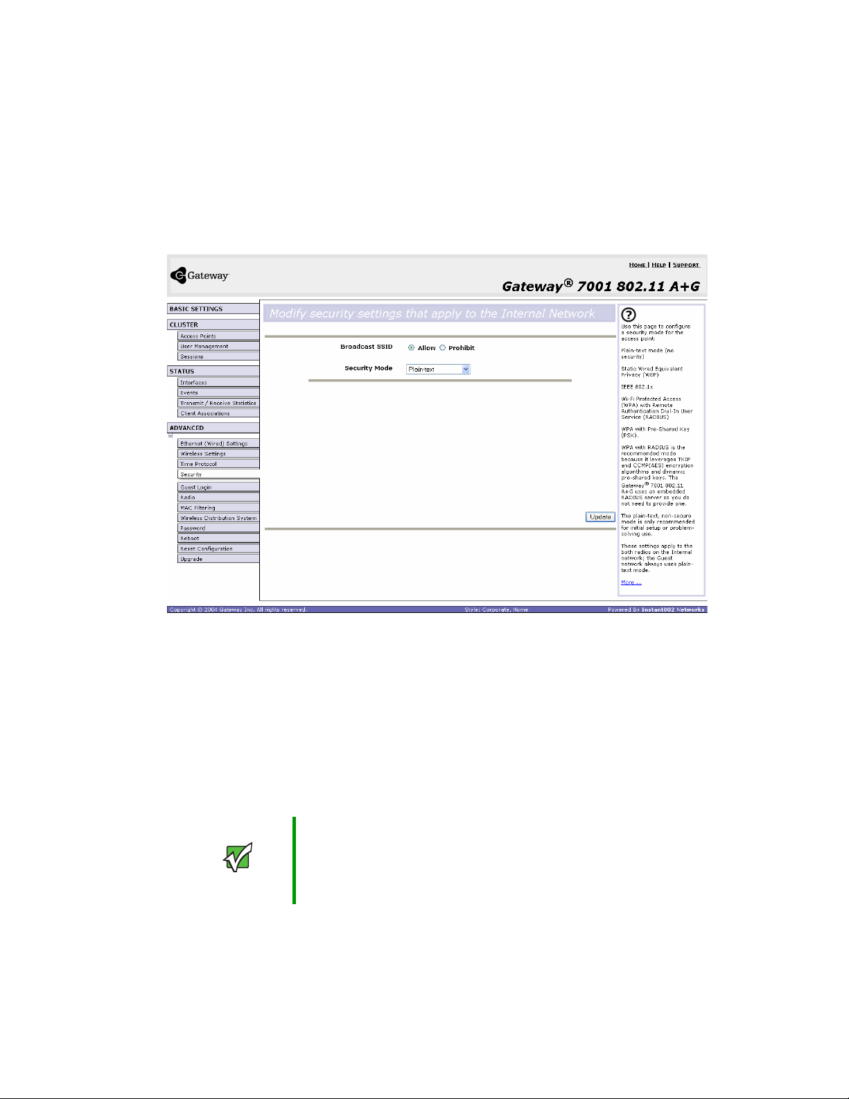
Configuring network security
Navigating to security settings
To set the security mode, click Advanced > Security on the Administration Web page. The
Modify security settings that apply to the internal network screen opens. Update the boxes as
described in the following section.
Configuring security settings
The following configuration information explains how to configure security modes on the
access point.
Keep in mind that each wireless client that wants to exchange data with the access point
must be configured with the same security mode and encryption key settings consistent
with access point security.
On a dual-band AP, these Security Settings apply to both radios.
Important Security modes other than plain-text apply only to
configuration of the internal network. On the guest
network, you can use only plain-text mode. (For more
information about guest networks, see “Setting up Guest
Access” on page 95.)
www.gateway.com
83
Page 89

Chapter 7: Advanced Configuration
Broadcast SSID and Security Mode
To configure security on the access point, select a security mode and fill in the related
boxes as described in the following table. (Note you can also allow or prohibit the Broadcast
SSID as an extra precaution as mentioned in the following section.)
Field Description
Broadcast SSID Select the Broadcast SSID setting by clicking Allow or Prohibit option.
By default, the access point broadcasts the
its beacon frames. Suppress this broadcast to discourage stations from
automatically discovering your access point.
You can suppress (prohibit) this broadcast to discourage stations from
automatically discovering your access point. When the AP’s broadcast SSID
is suppressed, the network name will not be displayed in the List of Available
Networks on a client station. Instead, the client must have the exact network
name configured in the supplicant before it will be able to connect.
Security Mode Select the Security Mode. Select one of the following:
• Plain-text
• Static WEP
• IEEE 802.1x
• WPA with RADIUS
• WPA-PSK
For a guest network, only the Plain-text setting can be used. (For more
information, see “Setting up Guest Access” on page 95.)
Security modes other than plain-text apply only to configuration of the internal
network. On the guest network, you can use only plain-text mode.
Service Set Identifier
(SSID) in
Plain-text
Plain Text means any data transferred to and from the Gateway 7001 Series self-managed
AP is not encrypted.
There are no further options for plain-text mode.
Plain text mode can be useful during initial network configuration or for problem solving,
but it is not recommended for regular use on the internal network because it is not secure.
Guest Network
Plain text mode is the only mode in which you can run the guest network, which is by
definition an unsecure LAN always virtually or physically separated from any sensitive
information on the internal LAN.
The absence of security on the Guest AP is designed to make it as easy as possible for guests
to get a connection without having to program any security settings in their clients.
84
www.gateway.com
Page 90

Configuring network security
For a minimum level of protection on a guest network, you can choose to suppress
(prohibit) the broadcast of the SSID (network name) to discourage client stations from
automatically discovering your access point. (See also “Does Prohibiting the Broadcast SSID
Enhance Security?” on page 82.)
(For more about the guest network, see “Setting up Guest Access” on page 95.)
Static WEP
Wired Equivalent Privacy (WEP) is a data encryption protocol for 802.11 wireless networks.
All wireless stations and access points on the network are configured with a static 64-bit
(40-bit secret key + 24-bit initialization vector (IV)) or 128-bit (104-bit secret key + 24-bit
IV) Shared Key for data encryption.
You cannot mix 64-bit and 128-bit WEP keys between the access point and its client
stations.
Static WEP is not the most secure mode available, but it offers more protection than
plain-text mode as it does prevent an outsider from easily sniffing out unencrypted wireless
traffic. (For more secure modes, see the sections on “IEEE 802.1x” on page 89, “WPA with
RADIUS” on page 91, or “WPA-PSK” on page 93.) WEP encrypts data moving across the
wireless network based on a static key. (The encryption algorithm is a “stream” cipher called
RC4.)
The access point uses a key to transmit data to the client stations. Each client station must
use that same key to decrypt data it receives from the access point.
Client stations can use different keys to transmit data to the access point. (Or they can
all use the same key, but this is less secure because it means one station can decrypt the
data being sent by another.) If you selected “Static WEP” security mode, provide the
following on the access point settings:
www.gateway.com
85
Page 91

Chapter 7: Advanced Configuration
Field Description
Transfer Key
Index
Key Length Specify the length of the key by clicking one of the options:
Key Type Select the key type by clicking one of the options:
Characters
Required
WEP Keys You can specify up to four WEP keys. In each text box, type a string of
Select a key index from the list. Key indexes 1 through 4 are available. The
default is 1.
Transfer Key Index
The
to encrypt the data it transmits.
• 40 bits
• 104 bits
• ASCII
• Hex
Indicates the number of characters required in the WEP key.
The number of characters required updates automatically based on how you
set Key Length and Key Type.
characters for each key.
If you selected ASCII, type any combination of integers and letters 0-9, a-z,
and AZ.
If you selected HEX, type hexadecimal digits (any combination of 0-9 and
a-f or A-F).
Use the same number of characters for each key as specified in the
Characters Required box. These are the RC4 WEP keys shared with the
stations using the access point.
Each client station must be configured to use one of these same WEP keys
in the same slot as specified here on the AP. (See “Rules to Remember for
Static WEP” on page 87.)
indicates which WEP key the access point will use
86
www.gateway.com
Page 92

Field Description
Configuring network security
Authentication
Algorithm
The authentication algorithm defines the method used to determine whether
a client station is allowed to associate with an access point when static WEP
is the security mode.
Specify the authentication algorithm you want to use by choosing one of the
following from the list:
• Open System
• Shared Key
• Both
Open System authentication lets any client station associate with the access
point whether that client station has the correct WEP key or not. This is
algorithm is also used in plain text, IEEE 802.1x, and WPA modes. When
the authentication algorithm is set to Open System, any client can associate
with the access point.
Note that just because a client station is allowed to associate does not ensure
it can exchange traffic with an access point. A station must have the correct
WEP key to be able to successfully access and decrypt data from an access
point, and to transmit readable data to the access point.
Shared Key authentication requires the client station to have the correct
WEP key in order to associate with the access point. When the authentication
algorithm is set to Shared Key, a station with an incorrect WEP key will not
be able to associate with the access point.
Both is the default. When the authentication algorithm is set to Both:
• Client stations configured to use WEP in shared key mode must have a
valid WEP key in order to associate with the access point.
• Client stations configured to use WEP as an open system (shared key mode
not enabled) will be able to associate with the access point even if they do
not have the correct WEP key.
Rules to Remember for Static WEP
■ All client stations must have the Wireless LAN (WLAN) security set to WEP and all
clients must have one of the WEP keys specified on the AP in order to de-code
AP-to-station data transmissions.
■ The AP must have all keys used by clients for station-to-AP transmit so that it can
de-code the station transmissions.
■ The same key most occupy the same slot on all nodes (AP and clients). For example if
the AP defines abc123 key as WEP key 3, then the client stations must define that same
string as WEP key 3.
■ On some wireless client software (like Funk Odyssey), you can configure multiple WEP
keys and define a client station transfer key index, then set the stations to encrypt the
data they transmit using different keys. This ensures that neighboring APs cannot
decode each other’s transmissions.
www.gateway.com
87
Page 93

Chapter 7: Advanced Configuration
Example of Using Static WEP
For a simple example, suppose you configure three WEP keys on the access point. In our
example, the Transfer Key Index for the AP is set to
slot 3 is the key the access point will use to encrypt the data it sends.
You must then set all client stations to use WEP and provide each client with one of the
slot/key combinations you defined on the AP.
3. This means that the WEP key in
For this example, we will set WEP Key index to
1 on a Windows client.
88
www.gateway.com
Page 94

Configuring network security
If you have a second client station, that station also needs to have one of the WEP keys
defined on the AP. You could give it the same WEP key you gave to the first station. Or
for a more secure solution, you could give the second station a different WEP key (key 2,
for example) so that the two stations cannot decrypt each other’s transmissions.
Static WEP with Transfer Key Indexes on Client Stations
Some Wireless client software (like Funk Odyssey) lets you configure multiple WEP keys
and set a transfer index on the client station, then you can specify different keys to be
used for station-to-AP transmissions. (The standard Windows wireless client software does
not allow you to do this.)
To build on our example, using Funk Odyssey client software you could give each of the
clients WEP key 3 so that they can decode the AP transmissions with that key and also
give client 1 WEP key 1 and set this as its transfer key. You could then give client 2 WEP
key 2 and set this as its transfer key index.
The following figure illustrates the dynamics of the AP and two client stations using
multiple WEP keys and a transfer key index.
can decrypt WEP key 3
transmits in WEP key 1
1
y
e
k
P
E
W
W
3
y
e
k
P
E
Client station 1
WEP key 3
can decrypt WEP key 3
transmits in WEP key 2
Access point transmits to both stations with the same
WEP key (for example, WEP key 3
WEP key 2
Client station 2
IEEE 802.1x
IEEE 802.1x is a standard for network access control. It involves passing the Extensible
Authentication Protocol (EAP) over IEEE 802.11 LANs using a protocol called EAP
Encapsulation Over LANs (EAPOL).
This mode requires the use of a RADIUS server to authenticate users, and configuration
of user accounts through the
The access point requires a RADIUS server capable of EAP, such as the Microsoft Internet
Authentication Server or the Gateway 7001 Series self-managed AP internal authentication
server. To work with Windows clients, the authentication server must support Protected
EAP (PEAP) and MSCHAP V2.
Cluster > User Management tab.
www.gateway.com
89
Page 95

Chapter 7: Advanced Configuration
When configuring IEEE 802.1x mode, you have a choice of whether to use the embedded
RADIUS server or an external RADIUS server that you provide. The Gateway 7001 Series
self-managed AP embedded RADIUS server supports Protected EAP (PEAP) and MSCHAP
V2.
If you use your own RADIUS server, you have the option of using any of a variety of
authentication methods that the IEEE 802.1x mode supports, including certificates,
Kerberos, and public key authentication. Keep in mind, however, that the client stations
must be configured to use the same authentication method being used by the access point.
If you selected “IEEE 802.1x” Security Mode, provide the following:
Field Description
Authentication
Server
Radius IP Type the Radius IP in the text box.
Radius Key Type the Radius Key in the text box.
Select one of the following from the list:
■
Built-in - To use the authentication server provided with the Gateway 7001
Series self-managed AP. If you choose this option, you do not have to
provide the Radius IP and Radius Key (they are automatically provided).
■
External - To use an external authentication server. If you choose this
option you must supply a Radius IP and Radius Key of the server you want
to use.
Radius IP
The
The Gateway 7001 Series self-managed AP internal authentication server
is 127.0.0.1. This will be provided automatically if you selected the built-in
authentication server.
For more information, see “Managing User Accounts” on page 51.
Radius Key
The
you type will be displayed as “*” characters to prevent others from seeing
the RADIUS key as you type.
The Gateway 7001 Series self-managed AP internal authentication server
is “secret.” This will be provided automatically if you selected the built-in
authentication server.
This value is never sent over the network.
is the IP address of the RADIUS server.
is the shared secret key for the RADIUS server. The text
90
www.gateway.com
Page 96
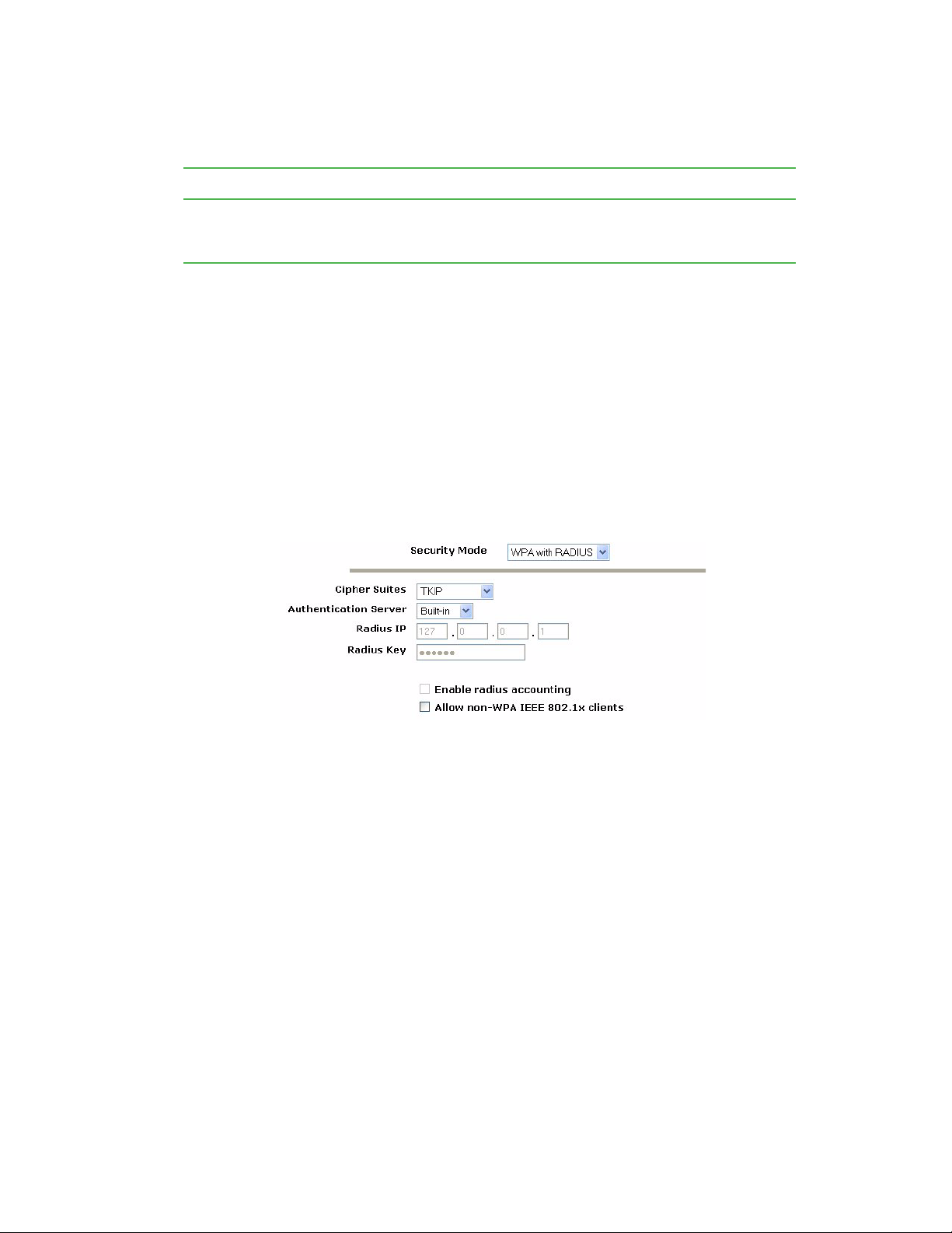
Field Description
Configuring network security
Enable RADIUS
Accounting
Click Enable RADIUS Accounting if you want to track and measure the
resources a particular user has consumed such system time, amount of data
transmitted and received, and so on.
WPA with RADIUS
Wi-Fi Protected Access (WPA) with Remote Authentication Dial-In User Service (RADIUS) is a
Wi-Fi Alliance subset of IEEE 802.11i, which includes Temporal Key Integrity Protocol
(TKIP), Counter mode/ CBC-MAC Protocol (CCMP) Advanced Encryption Standard (AES),
and 802.1x mechanisms. This mode requires the use of a RADIUS server to authenticate
users.
When configuring WPA with RADIUS mode, you have a choice of whether to use the
embedded RADIUS server or an external RADIUS server that you provide. The Gateway
7001 Series self-managed AP embedded RADIUS server supports Protected EAP (PEAP) and
MSCHAP V2.
If you selected
WPA with RADIUS security mode, provide the following:
www.gateway.com
91
Page 97

Chapter 7: Advanced Configuration
Field Description
Cipher Suites Select the cipher you want to use from the list:
• TKIP
• CCMP (AES)
• Both
Temporal Key Integrity Protocol (TKIP) is the default.
TKIP provides a more secure encryption solution than WEP keys. The TKIP
process more frequently changes the encryption key used and better
ensures that the same key will not be re-used to encrypt data (a weakness
of WEP). TKIP uses a 128-bit “temporal key” shared by clients and access
points. The temporal key is combined with the client's MAC address and a
16-octet initialization vector to produce the key that will encrypt the data. This
ensures that each client station uses a different key to encrypt data. TKIP
uses RC4 to perform the encryption, which is the same as WEP. But TKIP
changes temporal keys every 10,000 packets and distributes them, thereby
greatly improving the security of the network.
Counter mode/CBC-MAC Protocol (CCMP) is an encryption method for
IEEE 802.11i that uses the Advanced Encryption Algorithm (AES). It uses
a CCM combined with Cipher Block Chaining Counter mode (CBC-CTR) and
Cipher Block Chaining Message Authentication Code (CBC-MAC) for
encryption and message integrity.
When the authentication algorithm is set to Both, both TKIP and AES clients
can associate with the access point. Client stations configured to use WPA
with RADIUS must have one of the following to be able to associate with
the AP:
• A valid TKIP RADIUS IP address and valid shared Key
• A valid CCMP (AES) IP address and valid shared Key
Clients not configured to use WPA-PSK will not be able to associate with AP.
Both is the default. When the authentication algorithm is set to Both, client
stations configured to use WPA with RADIUS must have one of the following:
• A valid TKIP RADIUS IP address and RADIUS Key
• A valid CCMP (AES) IP address and RADIUS Key
92
Authentication
Server
Select one of the following from the list:
■
Built-in - To use the authentication server provided with the Gateway 7001
Series self-managed AP. If you choose this option, you do not have to
provide the Radius IP and Radius Key (they are automatically provided).
■
External - To use an external authentication server. If you choose this
option you must supply a Radius IP and Radius Key of the server you want
to use.
www.gateway.com
Page 98

Field Description
Radius IP Type the Radius IP in the text box.
Radius IP
The
The RADIUS IP address for the Gateway 7001 Series self-managed AP
internal authentication server is 127.0.0.1. This will be provided
automatically if you selected the built-in authentication server.
For information on setting up user accounts, see “Managing User Accounts”
on page 51.
Radius Key Type the Radius Key in the text box.
Radius Key
The
you type will be displayed as “*” characters to prevent others from seeing
the RADIUS key as you type.
The Gateway 7001 Series self-managed AP internal authentication server
key is “secret.” This will be provided automatically if you selected the built-in
authentication server.
This value is never sent over the network.
Key Type Select the key type by clicking one of the options:
• ASCII
• HEX
is the IP address of the RADIUS server.
is the shared secret key for the RADIUS server. The text
Configuring network security
Enable RADIUS
Accounting
Allow non-WPA
Clients
Click Enable RADIUS Accounting if you want to enforce authentication for
WPA client stations with user names and passwords for each station.
Click Allow non-WPA clients if you want to let non-WPA (802.11),
unauthenticated client stations use this access point.
WPA-PSK
Wi-Fi Protected Access (WPA) with Pre-Shared Key (PSK) is a Wi-Fi Alliance subset of
IEEE 802.11i, which includes Temporal Key Integrity Protocol (TKIP), Advanced Encryption
Algorithm (AES), Counter mode/CBC-MAC Protocol (CCMP) 802.1x mechanisms. PSK
employs a pre-shared key. This is used for an initial check of credentials only.
If you selected “WPA-PSK” Security Mode, provide the following:
www.gateway.com
93
Page 99

Chapter 7: Advanced Configuration
Field Description
Cipher Suites Select the cipher you want to use from the list:
• TKIP
• CCMP (AES)
• Both
Temporal Key Integrity Protocol (TKIP) is the default.
TKIP provides a more secure encryption solution than WEP keys. The TKIP
process more frequently changes the encryption key used and better
ensures that the same key will not be re-used to encrypt data (a weakness
of WEP). TKIP uses a 128-bit “temporal key” shared by clients and access
points. The temporal key is combined with the client's MAC address and a
16-octet initialization vector to produce the key that will encrypt the data. This
ensures that each client station uses a different key to encrypt data. TKIP
uses RC4 to perform the encryption, which is the same as WEP. But TKIP
changes temporal keys every 10,000 packets and distributes them, thereby
greatly improving the security of the network.
Counter mode/CBC-MAC Protocol (CCMP) is an encryption method for
IEEE 802.11i that uses the Advanced Encryption Algorithm (AES). It uses
a CCM combined with Cipher Block Chaining Counter mode (CBC-CTR) and
Cipher Block Chaining Message Authentication Code (CBC-MAC) for
encryption and message integrity.
When the authentication algorithm is set to “Both”, both TKIP and AES
clients can associate with the access point. WPA clients must have one of
the following to be able to associate with the AP:
• A valid TKIP key
• A valid CCMP (AES) key
Clients not configured to use WPA-PSK will not be able to associate with AP.
Key The
Pre-shared Key
of at least 8 characters to a maximum of 63 characters.
Updating settings
To apply your changes, click Update.
94
is the shared secret key for WPA-PSK. Type a string
www.gateway.com
Page 100

Setting up Guest Access
Setting up Guest Access
Out-of-the-box guest interface features allow you to configure the Gateway 7001 Series
self-managed AP for controlled guest access to an isolated network. You can configure the
same access point to broadcast and function as two different wireless networks: a secure
Internal LAN and a public Guest network.
Guest clients can access the guest network without a user name or password. When guests
log in, they see a guest welcome screen (also known as a captive portal).
Understanding the guest interface
You can define unique parameters for guest connectivity and isolate guest clients from
other more sensitive areas of the network. No security is provided on the guest network
and only plain-text security mode is allowed.
Simultaneously, you can configure a secure internal network (using the same access point
as your guest interface) that provides full access to protected information behind a firewall
and requires secure logins or certificates for access.
You can configure a Gateway 7001 Series self-managed AP for the guest interface in one
of two ways:
■ Connect the access point to a separate network using the extra, dedicated guest network
port on the AP. This provides a physically secure solution that does not require VLAN
support. (For details on how to set up this type of guest interface, see “Configuring a
physically separate guest network” on page 96.)
■ Configure the access point using a single network with VLANs by setting up the guest
interface configuration options on the Administration Web pages for the Gateway 7001
Series self-managed AP. (For details on how to set up this type of guest interface, see
“Configuring a guest network on a virtual LAN” on page 97.)
Important Both methods leverage multiple BSSID and Virtual LAN
(VLAN) technologies that are built-in to the Gateway 7001
Series self-managed AP. The internal and guest networks
are implemented as multiple BSSIDs on the same access
point, each with different network names (SSIDs) on the
Wireless interface and different VLAN IDs on the Wired
interface.
On the dual-band radio (Gateway 7001 802.11 A+G
Wireless Access Point), the Guest Login settings apply to
both Radio One and Radio Two.
www.gateway.com
95
 Loading...