

Page 1

We reserve the right to modify technical specifications without prior notice.
UK830300/170717 © Alpha-InnoTec GmbH
COMPACT
Operating Manual
Heat Pumps
BRINE/WATER
UK
SWC – Series
Page 2

2
We reserve the right to modify technical specifications without prior notice.
UK830300/170717 © Alpha-InnoTec GmbH
Please read first
This operating manual provides important information on
the handling of the unit. It is an integral part of the product
and must be stored so that it is accessible in the immediate
vicinity of the unit. It must remain available throughout the
entire service life of the unit. It must be handed over to subsequent owners or operators of the unit.
Read the operating manual before working on or operating
the unit. This applies in particular to the chapter on safety.
Always follow all instructions completely and without restrictions.
It is possible that this operating manual may contain instructions that seem incomprehensible or unclear. In case of
questions or uncertainty, contact the factory customer service department or the manufacturer’s local service partner.
Since this operating manual was written for several different
models of the unit, always comply with the parameters for
the respective model.
This operating manual is intended only for persons assigned
to work on or operate the unit. Treat all constituent parts
confidentially. The information contained herein is protected by copyright. No part of this operating manual may
be reproduced, transmitted, copied, stored in electronic data
systems or translated into another language, either wholly
or in part, without the express written permission of the
manufacturer.
Symbols
The symbols used in the operating manual have the following meaning:
Information for operators.
Information or instructions for qualified techni-
cians.
DANGER!
Failure to observe this information could
result in immediate danger to life and limb.
WARNING!
Failure to observe this information could
result in serious personal injury.
CAUTION!
Failure to observe this information could
result in moderate or slight personal injury.
CAUTION.
Failure to observe this information could
result in material damage.
NOTICE.
Emphasized information.
Reference to other sections of the operating
manual.
Reference to other instructions of the manufac-
turer.
Page 3

3
We reserve the right to modify technical specifications without prior notice.
UK830300/170717 © Alpha-InnoTec GmbH
Contents
INFORMATION FOR OPERATORS AND
QUALIFIED TECHNICIANS
PLEASE READ FIRST ..............................................................................2
SYMBOLS ..................................................................................................
2
INTENDED USE ......................................................................................
4
EXCLUSION OF LIABILITY .................................................................
4
EC CONFORMITY .................................................................................
4
SAFETY ......................................................................................................
4
CUSTOMER SERVICE .............................................................................
5
WARRANTY / GUARANTEE ..............................................................
5
DISPOSAL .................................................................................................
5
INFORMATION FOR OPERATORS
FUNCTIONING PRINCIPLE OF THE HEAT PUMP SYSTEM .....6
AREA OF UTILIZATION .......................................................................
6
OPERATION .............................................................................................
6
COOLING FUNCTION ........................................................................
7
CARE OF THE UNIT ..............................................................................
8
MAINTENANCE OF THE UNIT .........................................................
8
MALFUNCTIONS ...................................................................................
8
INSTRUCTIONS FOR QUALIFIED TECHNICIANS
SCOPE OF DELIVERY ............................................................................ 9
INSTALLATION AND ASSEMBLY .......................................................
9
Installation area ................................................................................. 9
Transport to installation location .................................................. 9
Installation ........................................................................................10
Installation of the hydraulic connections ...................................11
Insulating the hydraulic connections...........................................13
Safety components .........................................................................13
Expansion vessels ............................................................................13
ELECTRICAL CONNECTIONS ........................................................
14
RINSING AND FILLING THE UNIT .................................................
16
Rinsing and filling the heat source...............................................17
Rinsing and filling the heating circuit ..........................................17
Cleaning and rinsing of unit components ..................................17
BLEEDING ...............................................................................................
17
Bleeding the unit .............................................................................17
Bleeding the circulating pump of the heating circuit ...............
17
Bleeding the circulating pump of the heat source ...................
17
Bleeding the heat source
for a unit without cooling function ......................................17
Bleeding the heat source
for a unit with cooling function ............................................18
OVERFLOW VALVE ...............................................................................
18
INSTALLATION OF THE HEAT PUMP
AND HEATING REGULATOR. ...................................................
19
MOUNTING AND REMOVAL OF THE SCREEN .........................
19
INSTALLATION OF THE ROOM THERMOSTAT
FOR THE COOLING FUNCTION ............................................20
HOT-WATER TANK ..............................................................................
21
COMMISSIONING
................................................................................22
DISMANTLING ......................................................................................
23
TECHNICAL DATA/SCOPE OF DELIVER
Y
SWC 60H(/K) – SWC 120H(/K) ................................................24
SWC 140H(/K) – SWC 330(/K) .................................................26
PERFORMANCE CURVE
S
Heating Capacity/COP / Power Consumption / Free Compressio
n
SWC 60H(/K) ..................................................................................
28
SWC 70H(/K) ..................................................................................29
SWC 80H(/K) ..................................................................................30
SWC 100H(/K) ................................................................................31
SWC 120H(/K) ................................................................................32
SWC 140H(/K) ................................................................................33
SWC 170H(/K) ................................................................................34
SWC 230(/K) ...................................................................................35
SWC 330(/K) ...................................................................................36
DIMENSIONAL DRAWINGS AND CLEARANCE DIMENSION
S
Size 1: Dimensional drawings .......................................................38
Size 1: Clearance dimensions .......................................................39
Size 2: Dimensional drawings .......................................................40
Size 2: Clearance dimensions .......................................................41
TERMINAL DIAGRAM
S
SWC 60H(/K) – SWC 170H(/K) ................................................42
SWC 230(/K) – SWC 330(/K) .....................................................43
CIRCUIT DIAGRAM
S
SWC 60H(/K) – SWC 80H(/K) ...................................................44
SWC 100H(/K) – SWC 170H(/K) ..............................................46
SWC 230(/K) ...................................................................................48
SWC 330(/K) ...................................................................................50
APPENDIX
EC DECLARATION OF CONFORMITY ........................................52
GENERAL CHECKLIST .......................................................................
53
COMPLETION REPORT FOR HEAT PUMP SYSTEMS ................
55
NOTES .....................................................................................................
57
CUSTOMER SERVICE
Addresses in the event of a service call.....................................58
Page 4

4
We reserve the right to modify technical specifications without prior notice.
UK830300/170717 © Alpha-InnoTec GmbH
Intended use
The unit may be used only for the intended use. This means:
•
for heating.
• for heating hot water.
• for cooling.
(Availability of the cooling function depends on
the model).
“Cooling function” section.
The unit may be operated only within its technical parameters.
Overview “Technical data/scope of delivery”.
NOTICE:
Notify the responsible power supply com-
pany of the use of a heat pump or heat pump
system.
Exclusion of liability
The manufacturer will not be liable for damage resulting
from unauthorized use of the unit.
The manufacturer’s liability will also be voided in the following cases:
•
if work is performed on the unit and its compo-
nents in a manner that does not comply with the
terms of this operating manual;
•
if work is performed on the unit and its components in an improper manner;
•
if work is performed on the unit that is not de-
scribed in this operating manual, and this work
was not expressly approved in writing by the
manufacturer;
•
if the unit or components in the unit are modified,
redesigned or removed without the express written permission of the manufacturer.
EC conformity
The unit bears the CE mark of conformity.
EC declaration of conformity
Safety
The unit is operational safe when used for the intended purpose. The construction and design of the unit conform to
the state of the art, all relevant DIN/VDE regulations and all
relevant safety regulations.
Every person who performs work on the unit must have
read and understood the operating manual prior to starting
any work. This also applies if the respective person has already worked with such a unit or a similar unit or has been
trained by the manufacturer.
Every person who performs work on the unit must comply
with the applicable accident prevention and safety regulations. This applies in particular to the wearing of personal
safety gear.
DANGER!
Unit operates under high electric voltage!
DANGER!
Only qualied technicians (trained heating,
cooling, refrigerant and electrical technicians) may perform work on the unit and its
components.
WARNING!
Observe safety labels on and in the unit.
DANGER!
Unit contains refrigerants!
WARNING!
Leaking refrigerant could result in personal
injury or material damage.
– Shut down unit.
– Ventilate installation location.
– Notify the manufacturer’s authorized
service center.
CAUTION.
For safety reasons:
Never disconnect the unit from the power
supply network.
Page 5

5
We reserve the right to modify technical specifications without prior notice.
UK830300/170717 © Alpha-InnoTec GmbH
Customer service
For technical assistance, contact the factory customer service department or the manufacturer’s local service partner.
Overview “Customer service”.
Warranty / Guarantee
For warranty and guarantee conditions, please refer to the
purchase documents.
NOTICE:
Please contact your dealer concerning war-
ranties and guarantees.
Disposal
When decommissioning the unit, always comply with applicable laws, directives and standards for the recovery, recycling
and disposal of materials and components of cooling units.
“Dismantling”.
Page 6

6
We reserve the right to modify technical specifications without prior notice.
UK830300/170717 © Alpha-InnoTec GmbH
Functioning principle of
the heat pump system
In a closed circuit, an environmentally compatible refrigerant is successively vaporized, condensed and liquefied. The
increase in pressure resulting from this process also causes
the temperature of the refrigerant to rise. This generates
high temperatures suitable for heating, for example by means
of floor or wall heating, or through radiators.
There are three ways to supply a heat pump with heat energy:
stored heat from the sun in the air, in the earth and in the
ground water. The heat generated from the respective heat
source (air, earth or water) and the heat pump is conveyed
to the heating system by means of a heat exchanger. Generally, water is used as a heating medium, and three types of
pumps - air/water, brine/water and water/water pumps – are
possible. A brine/water pump with floor heating, for example, takes about ¾ of the energy needed for heating from
the environment. Only about ¼ of the energy has to be supplied as electric power.
Example: drawing of a brine/water heat pump with floor
heating:
Area of utilization
Taking into consideration the ambient conditions, limits of
application and the applicable regulations, every heat pump
can be utilized in new or existing heating systems.
Overview “Technical data/scope of delivery”.
Operation
Your decision to purchase a heat pump or a heat pump
system is a long-term contribution to protecting the environment through low emissions and reduced primary
energy use.
You can operate and control the heat pump system with the
heat pump and heating regulator.
NOTICE:
Make sure that the control settings are cor-
rect.
Operating manual of the heat pump and heating
regulator.
To ensure that your heat pump or heat pump system operates efficiently and ecologically, the following are especially
important:
NOTICE:
Avoid unnecessarily high ow temperatures.
A lower ow temperature on the hot water
side increases the efciency of the system.
When letting in fresh air, do not leave windows open for an
extended period in order to save energy and reduce your
heating costs.
Page 7

7
We reserve the right to modify technical specifications without prior notice.
UK830300/170717 © Alpha-InnoTec GmbH
Cooling function
The cooling function is available only for heat pumps with
the model designator K.
It is not possible to retrofit heat pumps for cooling without
this designator. For the model designator, please refer to the
purchase documents. It is also on the rating plate attached
to the outside of the unit.
The cooling function is based on the principle of passive
cooling. An existing low temperature level is mixed to a temperature above the dew point and transferred to the heating
medium by means of a heat exchanger. The heat pump remains switched off during cooling; only the circulating pumps
for the heating circuit and the heat source are in operation.
The cooling power depends on the heat source temperature, which varies seasonally. For example, if the ground
stored more heat toward the end of the summer, the cooling power of a brine/water pump is reduced.
The effectiveness of passive cooling is generally not comparable to that of an air conditioning system.
NOTICE:
The use of the passive cooling function re-
quires oor or wall heating.
THE ROOM THERMOSTAT FOR THE COOLING FUNCTION
The room thermostat is used to switch the cooling function on and off:
I Cooling function on
Cooling function off
The heat pump regulation program activates the cooling
function only if the following conditions are fulfilled:
•
Heat pump model must have integrated cooling
function.
•
Room thermostat for the cooling function must
be switched on.
•
Temperature of the heat source must be ≥ +5 °C.
•
Heat pump must not currently be occupied with
“heating” or “water heating”.
If the heat pump regulation program sends the
command “water heating” to the heat pump, the
cooling function of the heat pump automatically
stops as long as the water is heating.
•
The “Automatic” settings must be selected on
the heat pump and heating regulator under “Operating mode: cooling”.
•
The outdoor temperature release set at the heat
pump and heating regulator must be exceeded.
Operating manual of the heat pump and heating
regulator.
Page 8

8
We reserve the right to modify technical specifications without prior notice.
UK830300/170717 © Alpha-InnoTec GmbH
Care of the unit
The outer surfaces of the unit can be cleaned with a damp
cloth and household cleaning products.
Do not use cleaning or care products that contain abrasives,
acids and/or chlorine. Such products would destroy the surfaces and could also damage the technical components of
the unit.
Maintenance of the unit
The cooling circuit of the heat pump requires no regular
maintenance.
The components of the heating circuit and the heat source
(valves, expansion vessels, circulating pumps) should be inspected annually by a qualified technician.
It is a good idea to have a maintenance contract with a
heating installation company. The company will conduct the
required maintenance at regular intervals.
Malfunctions
In the event of a malfunction, you can detect the cause of
the malfunction via the diagnostic program of the heat pump
and heating regulator.
Operating manual of the heat pump and heating
regulator.
DANGER!
Service and repair work on the components
of the unit may be performed only by customer service personnel authorized by the
manufacturer.
Overview “Customer service”.
Page 9

9
We reserve the right to modify technical specifications without prior notice.
UK830300/170717 © Alpha-InnoTec GmbH
Scope of delivery
Example of scope of delivery:
1 Compact unit
2 Screen
3 Vibration decouplers (only
for size 1 units)
4 Expansion vessel for heat circuit
5 Safety components for heat
circuit and heat source
6 Package with heat pump and heating
regulator, outdoor temperature
sensor, seals, sylomer strips, cap
valve and wall mount for heating
circuit expansion vessel, room
thermostat for cooling function
(only for models with designator
K), compensators (only for size 2
units; in additional cardboard box)
Proceed as follows:
Inspect delivery for outwardly visible signs of
damage…
Check to make sure that delivery is complete.
Any defects or incorrect deliveries must be claimed
immediately.
NOTICE:
Note the model.
Overview “Technical data/scope of delivery” or
rating plate on unit.
Installation and assembly
Observe the following when performing all work:
NOTICE:
Always comply with applicable accident pre-
vention regulations, with applicable statutory regulations, ordinances and directives.
WARNING!
The heat pump or heat pump system may
be installed and assembled only by a qualied
technician!
NOTICE:
Observe the sound levels of the respective
model.
Overview “Technical data/scope of delivery”,
“Sound” section.
INSTALLATION AREA
CAUTION.
Install the heat pump only indoors.
The installation area must be frost-free and dry. It must meet
the requirements of DIN EN 378. It must also fulfill applicable local regulations.
TRANSpORT TO INSTALLATION LOCATION
To avoid damage during transport, you should transport the
unit to the final installation location in its original packaging (with angle bracket on the wooden pallet), using a lifting
truck.
If it is not possible to transport the unit to the final installation location using a lifting truck, you can also transport the
heat pump using a hand truck.
DANGER!
Several people are required to transport the
unit. Do not underestimate the weight of the
heat pump.
Overview “Technical data/scope of delivery”, “Gen-
eral unit data” section.
Page 10

10
We reserve the right to modify technical specifications without prior notice.
UK830300/170717 © Alpha-InnoTec GmbH
INSTALLATION
DANGER!
Several people are required to install the
unit.
NOTICE:
Take into account the size of the unit.
Overview “Technical data/scope of delivery”, “Gen-
eral unit data” section.
NOTICE:
Always comply with required clearance di-
mensions.
Overview “Dimensional drawings” and “Clearance
dimensions” for the respective size.
Proceed as follows at the installation location:
Remove angle bracket, transport and packaging ma-
terial from the unit…
Dispose of angle bracket, transport and packaging
material properly and in accordance with ecological
principles.
Set unit on a solid and level, preferably sound-insu-
lated surface…
Compensate for minor unevenness using the pro-
vided sylomer strips…
The sylomer strips also provide for added stability
of the heat pump. They absorb sound and vibrations
transmitted to the underlying surface.
Place the sylomer strips under the heat pump as
follows:
•
Tip the unit slowly and carefully to one side…
CAUTION.
Never tilt the unit more than a maximum of
45°.
DANGER!
The unit can tip when being removed from
the wooden pallet and during transport with
a hand truck. This can result in personal
injury and damage to the unit.
– Take suitable precautionary measures
to eliminate the danger of tipping.
We recommend removing the front panel to reduce the
weight of the unit for further transport.
Loosen quick-release screws for the front panel.
Turn counter-clockwise 90°…
Lift front panel and set aside in a safe place.
DANGER!
Make sure to secure unit against slipping
during transport.
CAUTION.
Never use components and hydraulic con-
nections on the unit for purposes of transport.
CAUTION.
Do not damage the hydraulic connections
under any circumstances.
CAUTION.
Do not tilt the unit more than a maximum of
45° (in any direction).
Page 11

11
We reserve the right to modify technical specifications without prior notice.
UK830300/170717 © Alpha-InnoTec GmbH
WARNING!
Hands and ngers could be crushed during
the following tasks!
Secure unit in raised position so that it cannot accidentally tip back into the original position.
•
Place one sylomer strip flush with the respective
outer edge of the unit…
•
Slowly and carefully tip the unit back into the origi-
nal position…
Repeat steps
•
through
•
for the remaining
sides of the unit.
Place sylomer strips at right angles to each other,
with no space in between:
Operating side
INSTALLATION OF THE HydRAULIC CONNECTIONS
CAUTION.
The heat source system must be designed
according to the specications of the heat
pump guide.
Heat pump guide and “Hydraulic connection” in-
structions.
NOTICE:
Check to make sure that the diameters and
lengths of the pipes for the heating circuit
and the heat source are sufciently dimensioned. The free compression of the circulating pumps must be able to deliver at least the
minimum ow rate required for your model.
Overview “Technical data/scope of delivery”, “Heat
source” and “Heating circuit” sections.
DANGER!
Disconnect unit from power supply if it is
connected to the power supply!
Proceed as follows:
Install shut-off devices at the heating circuit…
Install shut-off devices at the heat source.
NOTICE:
During installation of the shut-off devices, the
compressor and liqueer of the heat pump
can be rinsed, if necessary.
CAUTION!
The condenser may be rinsed only by cus-
tomer service personnel authorized by the
manufacturer.
CAUTION.
When installing the connections, always
secure the connections on the unit from
twisting, in order to prevent damage to the
copper pipes in the interior of the unit.
Page 12

12
We reserve the right to modify technical specifications without prior notice.
UK830300/170717 © Alpha-InnoTec GmbH
The connections for the heating circuit or the heat source
are located on the back of the unit:
1 Hot water outflow (forward flow)
2 Hot water inflow (return flow)
3 Heat source inflow (return flow)
4 Heat source outflow (forward flow)
INSTALLATION ON SIzE 1 UNITS
Proceed as follows:
We recommend installing a contamination filter
(screen size 0.9 mm) on the heat source inflow
(return flow) connection…
Connect the pipes of the heating circuit and the
heat source with the corresponding connections on
the back of the unit. Use vibration decouplers.
These are included in the scope of delivery. They must be
installed in order to prevent damage from vibrations to the
pipes.
Arrange the vibration decouplers in a quarter circle, as
shown in the following drawing:
A straight or extended hose arrangement for the vibration
decoupler is not permitted.
Page 13

13
We reserve the right to modify technical specifications without prior notice.
UK830300/170717 © Alpha-InnoTec GmbH
INSULATING THE HydRAULIC CONNECTIONS
The vibration decouplers and the pipes of the heat source
must be insulated so that they are sealed against vapor diffusion.
NOTICE:
Insulate in accordance with applicable local
standards and directives.
SAFETy COMpONENTS
The safety components are packed in the extra box.
The connections for the safety components are located at
the top rear on the outside of the unit.
1 Connection for heating
circuit safety component
2 Connection for heat source
safety component
Proceed as follows:
Install safety component for the heating circuit…
Install safety component for the heat source.
ExpANSION vESSELS
The expansion vessel for the heat source is integrated in
the unit.
The expansion vessel for the heating circuit and the corresponding cap valve are included in the scope of delivery. They
must be integrated in the heating circuit on-site in compliance with the applicable standards and directives.
INSTALLATION ON SIzE 2 UNITS
The included compensators must be used for connection
to the pipes:
The compensators also serve as vibration decouplers.
The compensators are packed in the extra box.
Proceed as follows:
We recommend installing a contamination filter
(screen size 0.9 mm) on the heat source inflow
(return flow) connection…
Screw the compensators by hand onto the connec-
tions on the unit until they bear against the rubber
gasket…
Screw the compensators by hand onto the pipes of
the heating circuit and the heat source until they
bear against the rubber gasket…
Using a suitable tool (e.g. a pipe wrench) to tighten
all connections one or two turns to achieve a tight
seal.
Do not overtighten. The rubber part of the com
pensators must not become twisted (torsion). This
could cause malfunctions and even serious damage
to the unit.
Page 14

14
We reserve the right to modify technical specifications without prior notice.
UK830300/170717 © Alpha-InnoTec GmbH
2 Size 2:
Switch cabinet closed.
Insert load and control leads in the openings provided on the back of the unit…
1 Cable duct size 1:
2 Cable duct size 2:
Electrical connections
Observe the following when performing all work:
DANGER!
Electrical connections may be installed only
by qualied electricians.
DANGER!
Observe the relevant EN, VDE and/or appli-
cable local safety regulations during the installation and during all electrical work.
Observe the technical connection conditions
of the responsible power supply company!
Loosen quick-release screws for the front panel.
Turn counter-clockwise 90°…
Lift front panel and set aside in a safe place…
Open electric switch cabinet (inside the unit on the
left)…
1 Size 1:
Switch cabinet closed.
Page 15

15
We reserve the right to modify technical specifications without prior notice.
UK830300/170717 © Alpha-InnoTec GmbH
Lay load and control leads in the cable duct inside
the unit all the way to the switch cabinet…
1 Size 1:
Switch cabinet opened.
2 Size 2:
Switch cabinet opened.
Install electrical connections according to the ter-
minal diagram and the circuit diagrams…
„Terminal diagrams” and “Circuit diagrams” for the
respective model.
DANGER!
Install electric connections only according
to the terminal diagram and the circuit diagrams that apply to your model.
CAUTION.
Ensure clockwise rotary eld of the load
power supply.
– An incorrect rotary eld of the con
denser during operation can cause
serious, irreparable damage to the condenser.
CAUTION.
Make sure to equip the power supply of the
heat pump with an all-pole circuit breaker.
The all-pole circuit breaker must have a contact gap
of at least 3mm.
CAUTION.
Make sure to equip the power supply of the
heat pump with a 3-pole automatic cut-out.
Note the level of the release current.
Overview “Technical data/scope of delivery”, “Elec-
tric” section.
After completion of all electrical installation work,
close the switch cabinet inside the unit…
Screw on the front panel of the unit if no further
installation work inside the unit is to be performed
immediately.
Page 16

16
We reserve the right to modify technical specifications without prior notice.
UK830300/170717 © Alpha-InnoTec GmbH
SIzE 2:
1 Safety component for heating circuit
2 Safety component for heat source
3 Servo-motor at mixing valve (only
on units with model designator K)
4 Overflow valve
5 Circulating pump for heat source
6 Expansion vessel for heat source
7 Fill/empty cock for heat source
8 Circulating pump for heating circuit
9 Fill/empty cock for heating circuit
Rinsing and filling the unit
DANGER!
Unit must be disconnected from the power
supply.
Open unit if this has not already been done…
Electrical connection work and .
Obtain overview of the interior of the unit.
DANGER!
The electric switch cabinet inside the unit
must be closed with the cabinet’s cover!
SIzE 1:
1 Safety component for heating circuit
2 Safety component for heat source
3 Servo-motor at mixing valve (only
on units with model designator K)
4 Overflow valve
5 Electric heating element
6 Circulating pump for heat source
7 Circulating pump for heating circuit
8 Fill/empty cock for heat source
9 Expansion vessel for heat source
10 Fill/empty cock for heating circuit
Page 17

17
We reserve the right to modify technical specifications without prior notice.
UK830300/170717 © Alpha-InnoTec GmbH
Bleeding
Proceed as follows:
Place a bleeder at the highest point of the heat source
in the heat source outflow (forward flow)…
If necessary, place a bleeder at the highest point of
the heat source in the heat source inflow (return
flow)…
Place a bleeder at the highest point of the heat-
ing circuit in the heating circuit outflow (forward
flow)…
If necessary, place a bleeder at the highest point
of the heating circuit in the heating circuit inflow
(return flow).
BLEEdING THE UNIT
The unit is bled automatically when the bleeders of the
safety components are open. If the heating circuit or heat
source is filled or emptied, the bleeding valves of the respective safety components open.
BLEEdING THE CIRCULATING pUMp OF THE HEATING
CIRCUIT
Loosen the screw-on cap in the middle of the circulating
pump.
BLEEdING THE CIRCULATING pUMp OF THE HEAT
SOURCE
Loosen the screw-on cap in the middle of the circulating
pump.
BLEEdING THE HEAT SOURCE FOR A UNIT wITHOUT
COOLING FUNCTION
Bleeding is conducted automatically by means of the integrated bleeding function in the safety component.
RINSING ANd FILLING THE HEAT SOURCE
Contamination and deposits in the heat source can cause
malfunctions.
Proceed as follows:
Rinse heat source system thoroughly…
Thoroughly mix the anti-freeze agent, available as an
accessory, with water at the required ratio. Add only
anti-freeze mixed with water to the heat source…
CAUTION.
The concentration of anti-freeze in the water
must be at least at the level specied for your
model.
Overview “Technical data/scope of delivery”, “Heat
source” section.
Check concentration of anti-freeze in the mix-
ture…
Fill heat source with the anti-freeze mixture.
RINSING ANd FILLING THE HEATING CIRCUIT
Contamination and deposits in the heating circuit can cause
malfunctions.
Rinse heating circuit system thoroughly…
Fill heating circuit.
CLEANING ANd RINSING OF UNIT COMpONENTS
CAUTION.
Unit components may be cleaned and rinsed
only by customer service personnel authorized by the manufacturer. Use only liquids
recommended by the manufacturer.
Rinsing of the liqueer with chemical clean
ing agents must be followed by neutralization of residue and intensive rinsing with
water. Always observe the technical data of
the manufacturer of the heat exchanger.
Page 18

18
We reserve the right to modify technical specifications without prior notice.
UK830300/170717 © Alpha-InnoTec GmbH
•
Switch on the circulating pump of the heat source
and allow to run…
•
After 2 minutes, with the circulating pump running,
turn wrench clockwise until the regulator of the
servo-motor is at 100 %…
Leave at this setting for 2 minutes…
•
With the circulating pump running, turn wrench
counter-clockwise until the regulator of the servomotor is at 50 %…
Turning the regulator to 50 % means an even mix
-
ture in the 3-way mixing valve from A and B to AB.
Reset servo-motor of the mixing valve to automatic
as soon as bleeding is completed.
NOTICE:
Push switch on servo-motor up.
Overflow valve
Set the overflow valve so that the spread between the forward and return flow is ≤ 10K (set at the factory to 200
mbar and sealed by paint).
BLEEdING THE HEAT SOURCE FOR A UNIT wITH COOLING FUNCTION
The bleeding must be conducted manually.
Proceed as follows:
Release the servo-motor at the mixing valve inside
the unit…
Push switch on servo-motor down…
Adjust mixing valve…
Use the wrench included in the scope of delivery.
Alternatively: Use a size 6 Allen wrench.
•
Insert wrench in the servo-motor…
•
Turn wrench counter-clockwise until the regulator
of the servo-motor is at 0 %…
Page 19
19
We reserve the right to modify technical specifications without prior notice.
UK830300/170717 © Alpha-InnoTec GmbH
Mounting and removal of the
screen
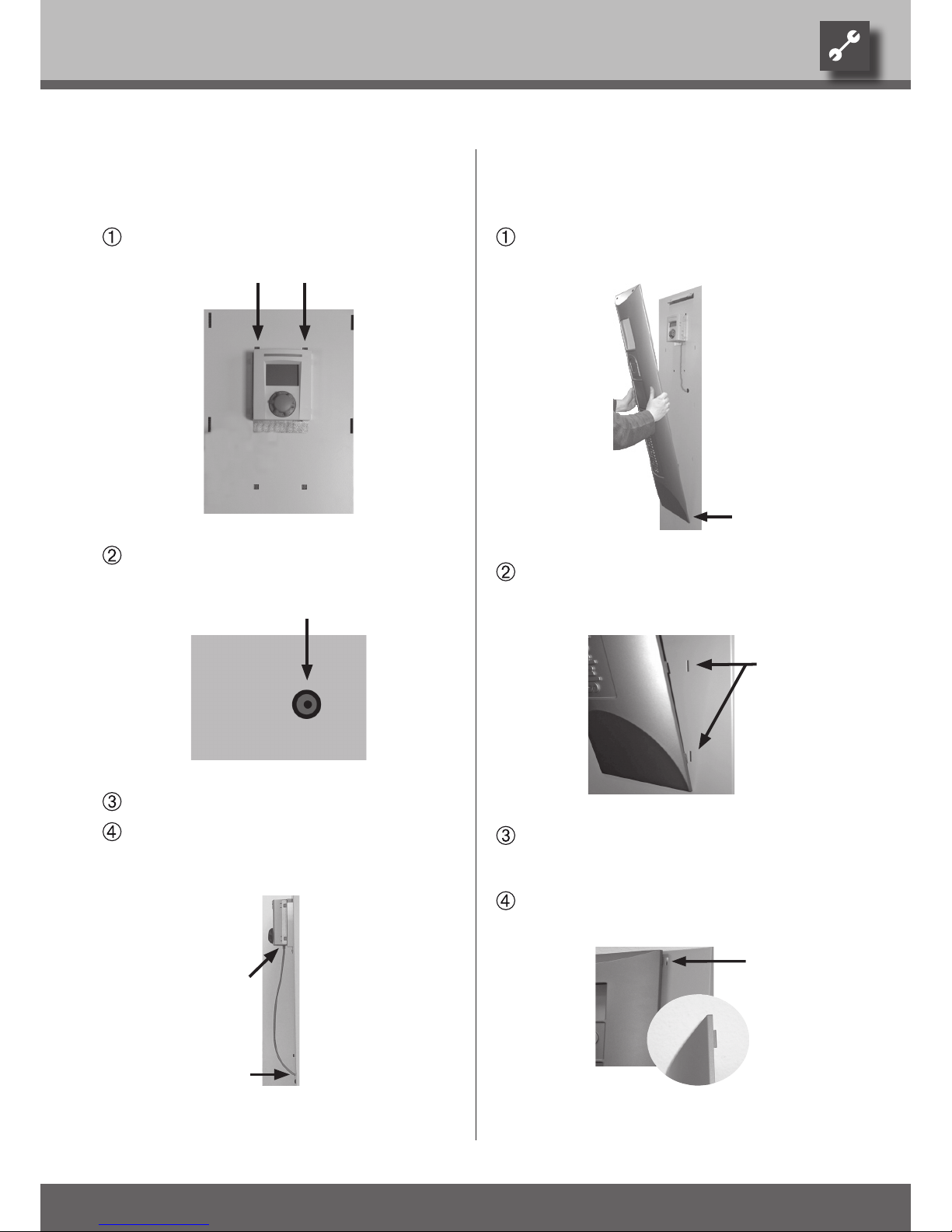
First, insert the screen at the bottom in the slot
provided on the front panel of the heat pump…
First, insert snap-in lugs on one side of the screen
from bottom to top in the slots provided on the
front panel of the unit…
Then, insert snap-in lugs on the other side of the
screen from bottom to top in the slots provided
on the front panel of the unit…
Finally, press the upper snap-in lugs of the screen
into the slots provided.
Installation of the heat pump
and heating regulator.
Suspend the heat pump and heating regulator in the
two square recesses in the front panel…
Lay the control cable for the regulator from the
inside of the unit through the sleeve in the front
panel to the outside…
Install the front panel on the unit…
Insert the control cable into the bushing provided
on the bottom of the heat pump and heating regulator.
Page 20
20
We reserve the right to modify technical specifications without prior notice.
UK830300/170717 © Alpha-InnoTec GmbH
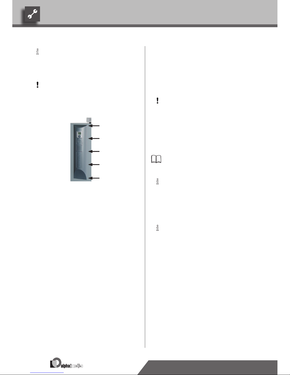
NOTICE:
To remove the screen, release the snap-
in lugs in the reverse order, i.e. from top to
bottom, without the use of tools.
CAUTION.
The snap-in lugs have a tight t. Press rmly
from the side against the screen toward the
middle, so that the snap-in lugs do not break
off.
Installation of the room
thermostat for the cooling
function
This chapter is relevant for you only if you are using a heat
pump with a model designator K.
CAUTION.
If oor heating systems are to be used for
cooling, the manufacturer must approve the
oor structure (especially the screed) for use
of the cooling function.
Use the room thermostat of the cooling function in a reference room as a reference variable. If the temperature in the
reference room falls below the set temperature, the cooling
function of the heat pump will automatically shut off.
Operating manual of the heat pump and heating
regulator, “Cooling” chapter.
NOTICE:
You must install the room thermostat in a
reference room in addition to single-room
regulators.
You must install single-room regulators for switch
-
ing from heating to cooling (and vice versa).
NOTICE:
Always comply with the applicable standards
and directives.
Page 21

21
We reserve the right to modify technical specifications without prior notice.
UK830300/170717 © Alpha-InnoTec GmbH
Hot-water tank
If the heat pump will be used for heating hot water, you must
integrate special hot-water tanks in the heat pump system.
NOTICE:
The hot-water tank must be equipped with a
heat exchanger, which is adapted to the heating capacity of the heat pump.
We offer a variety of hot-water tanks for you to choose
from. They are optimized for use with your heat pump.
NOTICE:
Integrate the hot-water tank in the heat
pump system corresponding to the hydraulic
diagram for your system.
For heating hot water, you must install a 3-way switching
valve in the hot water outflow (forward flow).
The 3-way switching valve is an accessory and is not included in the scope of delivery.
Page 22

22
We reserve the right to modify technical specifications without prior notice.
UK830300/170717 © Alpha-InnoTec GmbH
Commissioning
Proceed as follows:
Conduct a thorough installation inspection and go
through the items on the general checklist.
“General checklist”.
The installation inspection will prevent damage to
the heat pump system that could be caused by incorrect installation work.
Make sure of the following:
•
Clockwise rotary eld of the load power
supply (condenser).
•
Installation and assembly
of the heat pump ac-
cording to the information in this operating manual.
•
All electric installation work must be properly
completed.
•
Installation of an all-pole circuit breaker must be
installed for the condenser. It must have a contact
gap of at least 3 mm. A 3-pole automatic cut-out
must be installed.
•
The heating circuit and the heat source must be
rinsed, filled and bled thoroughly.
•
All valves and shut-off devices of the heating cir-
cuit must be open.
•
All valves and shut-off devices of the heat source
must be open.
•
All pipe systems and components of the system
must be sealed.
Carefully fill out and sign the completion report for
heat pump systems.
“Completion report for heat pump systems”.
In Germany:
Send completion report for heat pump systems to
the manufacturer’s factory customer service department.
Outside of Germany:
Send completion report for heat pump systems to
the manufacturer’s local partner.
Overview “Customer service”.
The heat pump system will be commissioned by
customer service personnel authorized by the manufacturer. There is a fee for commissioning!
Page 23

23
We reserve the right to modify technical specifications without prior notice.
UK830300/170717 © Alpha-InnoTec GmbH
Dismantling
DANGER!
Disconnect unit from power supply before
dismantling!
DANGER!
Only qualied electrical technicians are al-
lowed to disconnect the unit from the power
supply and de-install all electrical connections.
DANGER!
Only qualied heating or cooling system
technicians are allowed to remove the unit
from the system.
CAUTION.
The anti-freeze mixture of the heat source
must not be allowed to enter the sewer
system.
Collect anti-freeze mixture and dispose of
properly.
DANGER!
Only qualied cooling system technicians are
allowed to dismantle the unit and its components.
CAUTION.
Recycle or provide for proper disposal of unit
components, refrigerants and oil in accordance with the applicable regulations, standards and directives.
Page 24

24
We reserve the right to modify technical specifications without prior notice.
UK830300/170717 © Alpha-InnoTec GmbH
Gerätebezeichnung
Heat pump type Brine/water ı Air/water ı Water/water • applicable ı — not applicable
Installation location Indoors ı Outdoors • applicable ı — not applicable
Conformity CE
Performance data Heating capacity/COP at
B0/W35 Standard point acc. to EN14511
2 condensers
1 condensers
kW ı …
kW ı …
B0/W45 Standard point acc. to EN14511 kW ı …
B0/W35 Standard point acc. to EN255
2 condensers
1 condensers
kW ı …
kW ı …
Limits of application Heating circuit °C
Heat source °C
Additional operating points …
Sound Sound level measured at distance of 1m around the device (in reverberating room) dB(A)
Sound power level according to EN12102 dB
Heat source Volume ow: minimum ow rate ı nominal ow rate ı maximum ow rate l/h
Pressure loss heat pump ∆p (with cooling ∆pK) ı volume ow bar (bar) ı l/h
Free compression heat pump ∆p (with cooling ∆pK) ı volume ow bar (bar) ı l/h
Anti-freeze agent monoethylene glycol
minimum concentration ı frost proof down to % ı °C
Heating circuit Volume ow: minimum ow rate ı nominal ow rate ı maximum ow rate l/h
Pressure loss heat pump ∆p (with cooling ∆pK) ı volume ow bar (bar) ı l/h
Free compression heat pump ∆p (with cooling ∆pK) ı volume ow bar (bar) ı l/h
General unit data Dimensions (see dimensional drawing for the specied unit size) unit size
Total weight (including cooling) kg (kg)
Additional weight module 1 kg
Additional weight module 2 kg
Connections Heating circuit …
Heat source …
Refrigerant Refrigerant type ı Quantity … ı kg
Electric Voltage code ı all-pole circuit breaker heat pump *) … ı A
Voltage code ı circuit breaker control voltage *) … ı A
Voltage code ı circuit breaker electric heating element *) ı A
Heat Pump Effective power consumption in standard point B0/W35 according to EN14511: Power consumption ı current consumption ı cosφ kW ı A ı …
Maximum device current within the limits of application A
Starting current: direct ı with soft starter A ı A
Protection type IP
Output electric heating element 3 ı 2 ı 1 phase kW ı kW ı kW
Components Circulating pump heating circuit at nominal ow rate: Power consumption ı current consumption kW ı A
Circulating pump heat source at nominal ow rate: Power consumption ı current consumption kW ı A
Passive cooling function only for units with designator K: Cooling output at nominal volume ow (15 °C heat source, 25 °C heating water) kW
Safety equipment Safety component heating circuit ı Safety component heat source scope of delivery: • yes — no
Heating and heat pump regulator scope of delivery: • yes — no
Electronic soft starter integrated: • yes — no
Expansion vessels Heat source: Scope of delivery ı Volume ı Initial pressure • yes — no ı l ı bar
Heating circuit: Scope of delivery ı Volume ı Initial pressure • yes — no ı l ı bar
Overow valve integrated: • yes — no
Vibration decouplers Heating circuit ı heat source scope of delivery: • yes — no
UK813196
*) comply with local regulations n.n. = not detectable
Technical data/scope of delivery
Page 25

25
We reserve the right to modify technical specifications without prior notice.
UK830300/170717 © Alpha-InnoTec GmbH
SWC 80H(/K)
• ı — ı —
• ı —
•
—
8,9 ı 4,5
—
—
9,1 ı 4,7
20 – 65
-5 – 25
—
40
53
1450 ı 1900 ı 4000
— ı —
0,68 (0,66) ı 1450
•
25 ı -13
800 ı 1500 ı 1900
— ı —
0,41 (0,40) ı 1100
1
203 (218)
—
—
G1"AG
G1"AG
R407c ı 2,1
3~/PE/400V/50Hz ı C10
1~/N/PE/230V/50Hz ı B10
3~/N/PE/400V/50Hz ı C10
1,98 ı 3,7 ı 0,78
5,9
30 ı —
20
6 ı 4 ı 2
0,08 ı n.n.
0,2 ı n.n.
6,9
• ı •
•
—
• ı 12 ı 0,5
• ı 25 ı 1,5
•
• ı •
813170-a
SWC 100H(/K)
• ı — ı —
• ı —
•
—
10,2 ı 4,6
—
—
10,3 ı 4,7
20 – 65
-5 – 25
—
40
53
1600 ı 2200 ı 3500
— ı —
0,53 (0,50) ı 1600
•
25 ı -13
900 ı 1800 ı 2200
— ı —
0,34 (0,33) ı 1300
1
206 (221)
—
—
G1"AG
G1"AG
R407c ı 2,2
3~/PE/400V/50Hz ı C10
1~/N/PE/230V/50Hz ı B10
3~/N/PE/400V/50Hz ı C10
2,22 ı 4,1 ı 0,78
6,9
— ı 20
20
6 ı 4 ı 2
0,08 ı n.n.
0,2 ı n.n.
8,3
• ı •
•
•
• ı 12 ı 0,5
• ı 25 ı 1,5
•
• ı •
813171-a
SWC 120H(/K)
• ı — ı —
• ı —
•
—
11,7 ı 4,5
—
—
11,9 ı 4,7
20 – 62
-5 – 25
B–2 ı W65
40
53
1800 ı 2600 ı 3900
— ı —
0,51 (0,49) ı 2050
•
25 ı -13
1000 ı 2000 ı 2400
— ı —
0,32 (0,30) ı 1450
1
209 (224)
—
—
G1¼"AG
G1¼"AG
R407c ı 2,9
3~/PE/400V/50Hz ı C10
1~/N/PE/230V/50Hz ı B10
3~/N/PE/400V/50Hz ı C10
2,6 ı 4,8 ı 0,78
7,5
— ı 25
20
6 ı 4 ı 2
0,08 ı n.n.
0,2 ı n.n.
10,2
• ı •
•
•
• ı 18 ı 0,5
• ı 25 ı 1,5
•
• ı •
813172-a
SWC 60H(/K)
• ı — ı —
• ı —
•
—
5,7 ı 4,4
—
—
5,8 ı 4,7
20 – 65
-5 – 25
—
40
53
1000 ı 1400 ı 2500
— ı —
0,52 (0,5) ı 1100
•
25 ı -13
500 ı 950 ı 1400
— ı —
0,46 (0,45) ı 700
1
200 (214)
—
—
G1"AG
G1"AG
R407c ı 1,8
3~/PE/400V/50Hz ı C10
1~/N/PE/230V/50Hz ı B10
3~/N/PE/400V/50Hz ı C10
1,29 ı 2,4 ı 0,78
4,0
27,4 ı —
20
6 ı 4 ı 2
0,08 ı n.n.
0,1 ı n.n.
3,7
• ı •
•
—
• ı 12 ı 0,5
• ı 25 ı 1,5
•
• ı •
813169-a
SWC 70H(/K)
• ı — ı —
• ı —
•
—
6,9 ı 4,4
—
—
7,0 ı 4,5
20 – 65
-5 – 25
—
40
53
1250 ı 1650 ı 2500
— ı —
0,48 (0,46) ı 1250
•
25 ı -13
600 ı 1200 ı 1500
— ı —
0,47 (0,46) ı 850
1
202 (216)
—
—
G1“AG
G1“AG
R407c ı 2,0
3~/PE/400V/50Hz ı C10
1~/N/PE/230V/50Hz ı B10
3~/N/PE/400V/50Hz ı C10
1,57 ı 3,1 ı 0,73
5,0
29 ı —
20
6 ı 4 ı 2
0,08 ı n.n.
0,2 ı n.n.
5,3
• ı •
•
—
• ı 12 ı 0,5
• ı 25 ı 1,5
•
• ı •
813190
Page 26

26
We reserve the right to modify technical specifications without prior notice.
UK830300/170717 © Alpha-InnoTec GmbH
Gerätebezeichnung
Heat pump type Brine/water ı Air/water ı Water/water • applicable ı — not applicable
Installation location Indoors ı Outdoors • applicable ı — not applicable
Conformity CE
Performance data Heating capacity/COP at
B0/W35 Standard point acc. to EN14511
2 condensers
1 condensers
kW ı …
kW ı …
B0/W45 Standard point acc. to EN14511 kW ı …
B0/W35 Standard point acc. to EN255
2 condensers
1 condensers
kW ı …
kW ı …
Limits of application Heating circuit °C
Heat source °C
Additional operating points …
Sound Sound level measured at distance of 1m around the device (in reverberating room) dB(A)
Sound power level according to EN12102 dB
Heat source Volume ow: minimum ow rate ı nominal ow rate ı maximum ow rate l/h
Pressure loss heat pump ∆p (with cooling ∆pK) ı volume ow bar (bar) ı l/h
Free compression heat pump ∆p (with cooling ∆pK) ı volume ow bar (bar) ı l/h
Anti-freeze agent monoethylene glycol
minimum concentration ı frost proof down to % ı °C
Heating circuit Volume ow: minimum ow rate ı nominal ow rate ı maximum ow rate l/h
Pressure loss heat pump ∆p (with cooling ∆pK) ı volume ow bar (bar) ı l/h
Free compression heat pump ∆p (with cooling ∆pK) ı volume ow bar (bar) ı l/h
General unit data Dimensions (see dimensional drawing for the specied unit size) unit size
Total weight (including cooling) kg (kg)
Additional weight module 1 kg
Additional weight module 2 kg
Connections Heating circuit …
Heat source …
Refrigerant Refrigerant type ı Quantity … ı kg
Electric Voltage code ı all-pole circuit breaker heat pump *) … ı A
Voltage code ı circuit breaker control voltage *) … ı A
Voltage code ı circuit breaker electric heating element *) ı A
Heat Pump Effective power consumption in standard point B0/W35 according to EN14511: Power consumption ı current consumption ı cosφ kW ı A ı …
Maximum device current within the limits of application A
Starting current: direct ı with soft starter A ı A
Protection type IP
Output electric heating element 3 ı 2 ı 1 phase kW ı kW ı kW
Components Circulating pump heating circuit at nominal ow rate: Power consumption ı current consumption kW ı A
Circulating pump heat source at nominal ow rate: Power consumption ı current consumption kW ı A
Passive cooling function only for units with designator K: Cooling output at nominal volume ow (15 °C heat source, 25 °C heating water) kW
Safety equipment Safety component heating circuit ı Safety component heat source scope of delivery: • yes — no
Heating and heat pump regulator scope of delivery: • yes — no
Electronic soft starter integrated: • yes — no
Expansion vessels Heat source: Scope of delivery ı Volume ı Initial pressure • yes — no ı l ı bar
Heating circuit: Scope of delivery ı Volume ı Initial pressure • yes — no ı l ı bar
Overow valve integrated: • yes — no
Vibration decouplers Heating circuit ı heat source scope of delivery: • yes — no
UK813196
*) comply with local regulations n.n. = not detectable
Technical data/scope of delivery
Page 27

27
We reserve the right to modify technical specifications without prior notice.
UK830300/170717 © Alpha-InnoTec GmbH
SWC 140H(/K)
• ı — ı —
• ı —
•
—
13,7 ı 4,5
—
—
13,9 ı 4,7
20 – 65
-5 – 25
—
42
55
2350 ı 3100 ı 4700
— ı —
0,43 (0,41) ı 2350
•
25 ı -13
1200 ı 2400 ı 2900
— ı —
0,59 (0,57) ı 1700
1
212 (227)
—
—
G1¼"AG
G1¼"AG
R407c ı 2,7
3~/PE/400V/50Hz ı C13
1~/N/PE/230V/50Hz ı B10
3~/N/PE/400V/50Hz ı C16
3,0 ı 5,8 ı 0,75
9,4
— ı 28
20
9 ı 6 ı 3
0,2 ı n.n.
0,25 ı n.n.
9,8
• ı •
•
•
• ı 18 ı 0,5
• ı 35 ı 1,5
•
• ı •
813173-a
SWC 170H(/K)
• ı — ı —
• ı —
•
—
16,7 ı 4,6
—
—
16,9 ı 4,7
20 – 65
-5 – 25
—
43
56
2700 ı 3600 ı 5000
— ı —
0,36 (0,33) ı 2700
•
25 ı -13
1400 ı 2900 ı 3500
— ı —
0,58 (0,55) ı 2050
1
220 (235)
—
—
G1¼"AG
G1¼"AG
R407c ı 3,6
3~/PE/400V/50Hz ı C13
1~/N/PE/230V/50Hz ı B10
3~/N/PE/400V/50Hz ı C16
3,63 ı 6,7 ı 0,78
11,0
— ı 30
20
9 ı 6 ı 3
0,2 ı n.n.
0,25 ı n.n.
9,0
• ı •
•
•
• ı 18 ı 0,5
• ı 35 ı 1,5
•
• ı •
813174-a
SWC 230(/K)
• ı — ı —
• ı —
•
—
22,1 ı 4,3
—
—
22,5 ı 4,5
20 – 55
-5 – 25
—
47
60
3700 ı 4900 ı 5900
— ı —
0,74 (0,68) ı 3700
•
25 ı -13
1900 ı 3900 ı 4500
— ı —
0,41 (0,38) ı 2700
2
345 (360)
—
—
R1½"IG
R1½"IG
R407c ı 4,45
3~/PE/400V/50Hz ı C16
1~/N/PE/230V/50Hz ı B10
—
5,14 ı 9,5 ı 0,78
12,5
— ı 29,5
20
— ı — ı —
0,2 ı n.n.
0,35 ı n.n.
16,2
• ı •
•
•
• ı 24 ı 0,5
• ı 50 ı 1,5
•
• ı •
813175-a
SWC 330(/K)
• ı — ı —
• ı —
•
31,8 ı 4,1
17,6 ı 4,5
—
32,0 ı 4,3
17,9 ı 4,6
20 – 55
-5 – 25
—
47
60
5900 ı 7900 ı 10000
— ı —
0,42 (0,35) ı 5950
•
25 ı -13
2700 ı 5200 ı 6900
— ı —
0,70 (0,67) ı 3900
2
372 (390)
—
—
R1½"IG
R1½"IG
R407c ı 6,85
3~/PE/400V/50Hz ı C25
1~/N/PE/230V/50Hz ı B10
—
7,76 ı 14,4 ı 0,78
23,6
— ı 22
20
— ı — ı —
0,36 ı n.n.
0,35 ı n.n.
26,5
• ı •
•
•
• ı 24 ı 0,5
• ı 50 ı 1,5
•
• ı •
813176-a
Page 28
28
We reserve the right to modify technical specifications without prior notice.
UK830300/170717 © Alpha-InnoTec GmbH
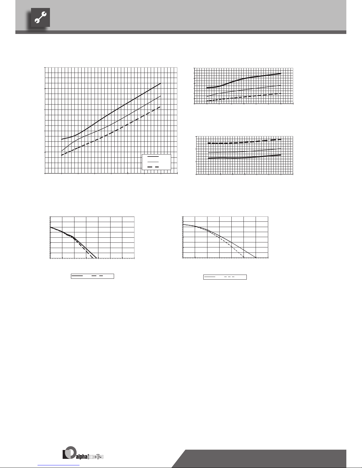
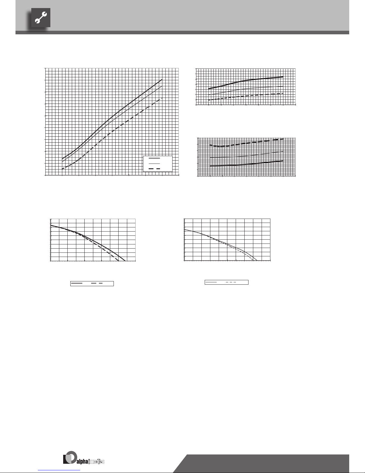
Performance curves
SWC 60H(/K)
Legend: UK823000L/170408
“” Volume ow, heating water
“„ Volume ow, heat source
Temp„ Temperature, heat source
Qh Heating capacity
Pe Power consumption
COP Coefcient of performance / efciency rating
∆p” / ∆p”† Free compression, heating circuit / free compression, heating circuit with cooling
∆p„ / ∆p„† Free compression, heat source / free compression, heat source with cooling
823000
Qh (kW)
2
4
6
8
10
12
-10 -5 0 5 10 15 20 25 30
Temp„ (°C)
35°C
50°C
65°C
COP
1
2
3
4
5
6
7
8
-10 -5 0 5 10 15 20 25 30
Temp„ (°C)
Pe (kW)
0
1
2
3
-10 -5 0 5 10 15 20 25 30
Temp„ (°C)
∆p (bar)
0,3
0,4
0,5
0,6
0,7
0,8
0,0
0,1
0,2
0,0 0,5 1,0 1,5 2,0 2,5 3,0 3,5
“”[m3/h]
ǻp” ǻp”†
∆p (bar)
0,3
0,4
0,5
0,6
0,7
0,8
0,0
0,1
0,2
0,0 0,5 1,0 1,5 2,0 2,5 3,0 3,5
“„[m3/h]
ǻp„ ǻp„†
Page 29
29
We reserve the right to modify technical specifications without prior notice.
UK830300/170717 © Alpha-InnoTec GmbH
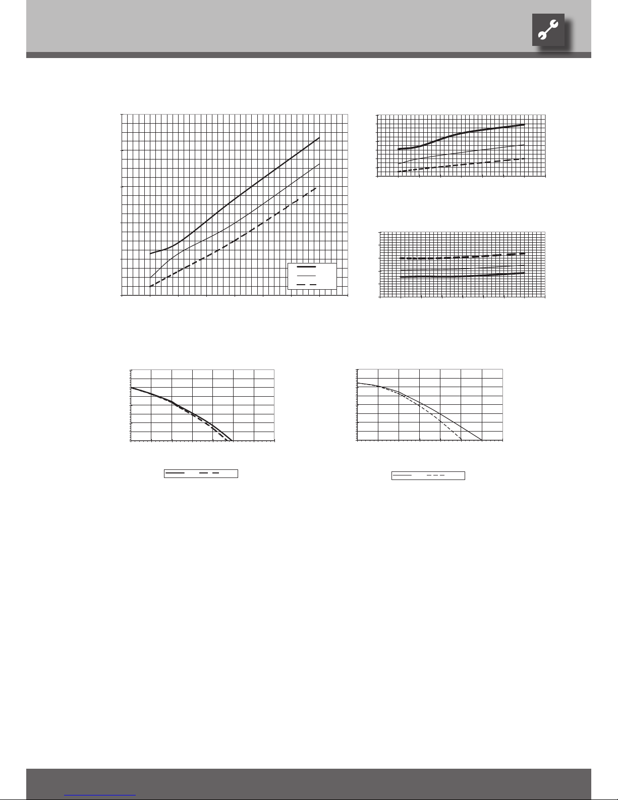
Performance curves
SWC 70H(/K)
823023
Qh (kW)
4
6
8
10
12
14
-10 -5 0 5 10 15 20 25 30
Temp„ (°C)
35°C
50°C
65°C
COP
1
2
3
4
5
6
7
8
-10 -5 0 5 10 15 20 25 30
Temp„ (°C)
Pe (kW)
0
1
2
3
4
5
-10 -5 0 5 10 15 20 25 30
Temp„ (°C)
∆p (bar)
0,0
0,1
0,2
0,3
0,4
0,5
0,6
0,7
0,8
0,0 0,5 1,0 1,5 2,0 2,5 3,0 3,5
“”
ǻp” ǻp”†
∆p (bar)
0,0
0,1
0,2
0,3
0,4
0,5
0,6
0,7
0,8
0,0 0,5 1,0 1,5 2,0 2,5 3,0 3,5
“„
ǻp„ ǻp„†
Legend: UK823000L/170408
“” Volume ow, heating water
“„ Volume ow, heat source
Temp„ Temperature, heat source
Qh Heating capacity
Pe Power consumption
COP Coefcient of performance / efciency rating
∆p” / ∆p”† Free compression, heating circuit / free compression, heating circuit with cooling
∆p„ / ∆p„† Free compression, heat source / free compression, heat source with cooling
Page 30
30
We reserve the right to modify technical specifications without prior notice.
UK830300/170717 © Alpha-InnoTec GmbH
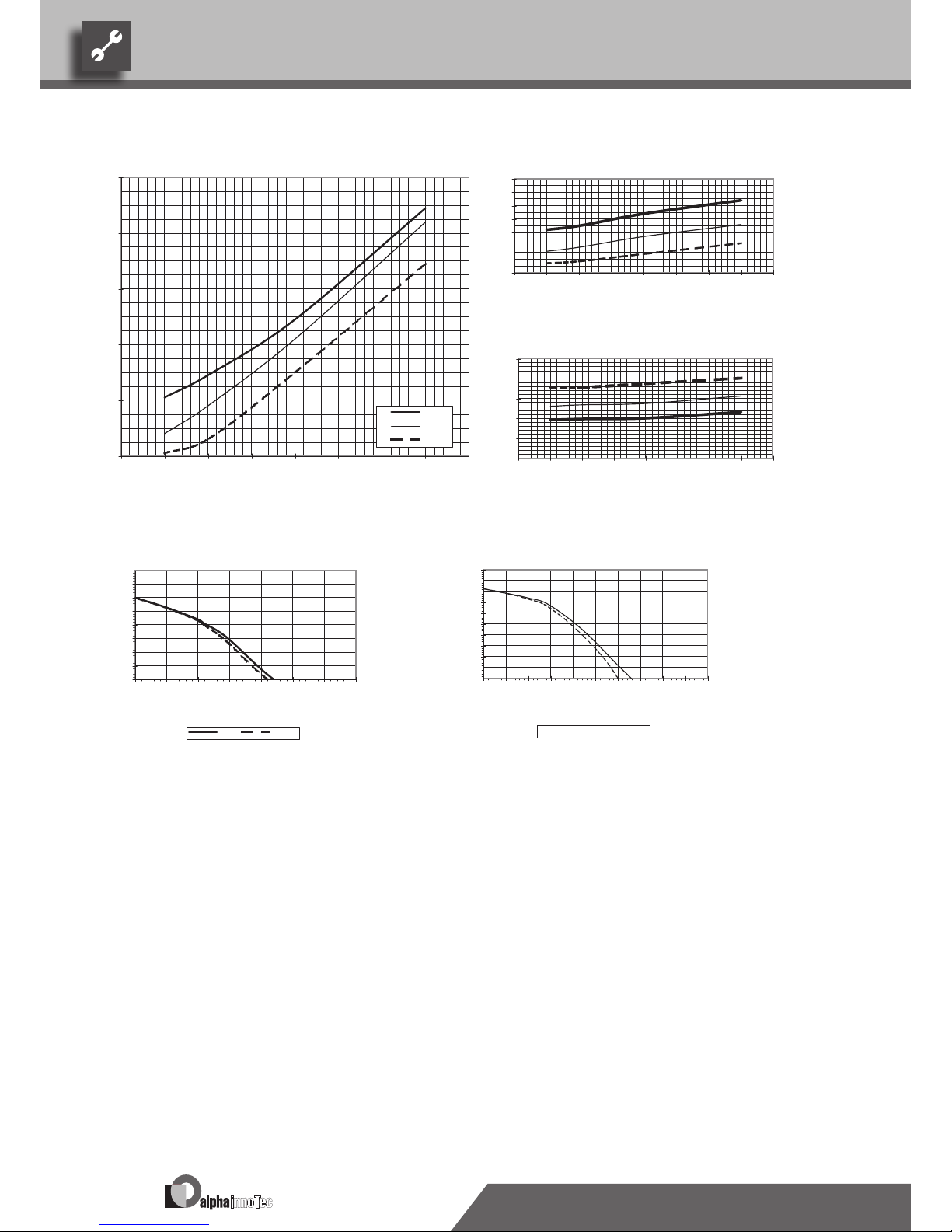
Performance curvesSWC 80H(/K)
Legend: UK823000L/170408
“” Volume ow, heating water
“„ Volume ow, heat source
Temp„ Temperature, heat source
Qh Heating capacity
Pe Power consumption
COP Coefcient of performance / efciency rating
∆p” / ∆p”† Free compression, heating circuit / free compression, heating circuit with cooling
∆p„ / ∆p„† Free compression, heat source / free compression, heat source with cooling
823001
Qh (kW)
6
8
10
12
14
16
-10 -5 0 5 10 15 20 25 30
Temp„ (°C)
35°C
50°C
65°C
COP
1
2
3
4
5
6
7
8
-10 -5 0 5 10 15 20 25 30
Temp„ (°C)
Pe (kW)
0
1
2
3
4
5
-10 -5 0 5 10 15 20 25 30
Temp„ (°C)
∆p (bar)
0,0
0,1
0,2
0,3
0,4
0,5
0,6
0,7
0,8
0,0 0,5 1,0 1,5 2,0 2,5 3,0 3,5
“”[m3/h]
ǻp” ǻp”†
∆p (bar)
0,0
0,1
0,2
0,3
0,4
0,5
0,6
0,7
0,8
0,9
1,0
0,0 0,5 1,0 1,5 2,0 2,5 3,0 3,5 4,0 4,5 5,0
“„[m3/h]
ǻp„ ǻp„†
Page 31
31
We reserve the right to modify technical specifications without prior notice.
UK830300/170717 © Alpha-InnoTec GmbH
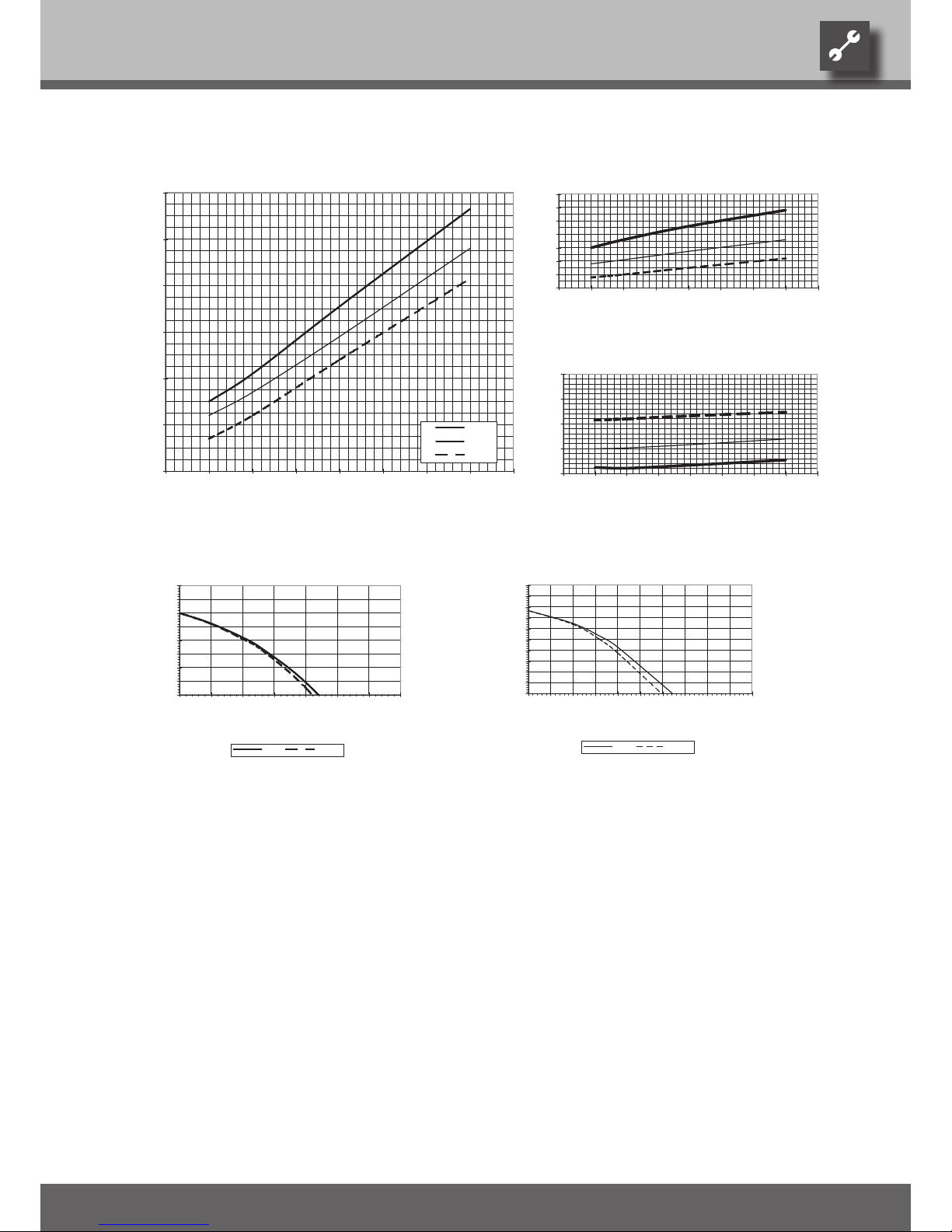
Performance curves SWC 100H(/K)
Legend: UK823000L/170408
“” Volume ow, heating water
“„ Volume ow, heat source
Temp„ Temperature, heat source
Qh Heating capacity
Pe Power consumption
COP Coefcient of performance / efciency rating
∆p” / ∆p”† Free compression, heating circuit / free compression, heating circuit with cooling
∆p„ / ∆p„† Free compression, heat source / free compression, heat source with cooling
823002
Qh (kW)
6
8
10
12
14
16
18
-10 -5 0 5 10 15 20 25 30
Temp„ (°C)
35°C
50°C
65°C
COP
1
2
3
4
5
6
7
8
-10 -5 0 5 10 15 20 25 30
Temp„ (°C)
Pe (kW)
2
3
4
5
6
-10 -5 0 5 10 15 20 25 30
Temp„ (°C)
∆p (bar)
0,0
0,1
0,2
0,3
0,4
0,5
0,6
0,7
0,8
0,0 0,5 1,0 1,5 2,0 2,5 3,0 3,5
“”[m3/h]
ǻp” ǻp”†
∆p (bar)
0,0
0,1
0,2
0,3
0,4
0,5
0,6
0,7
0,8
0,9
1,0
0,0 0,5 1,0 1,5 2,0 2,5 3,0 3,5 4,0 4,5 5,0
“„[m3/h]
ǻp„ ǻp„†
Page 32
32
We reserve the right to modify technical specifications without prior notice.
UK830300/170717 © Alpha-InnoTec GmbH
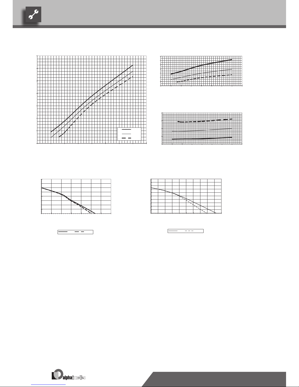
Performance curvesSWC 120H(/K)
Legend: UK823000L/170408
“” Volume ow, heating water
“„ Volume ow, heat source
Temp„ Temperature, heat source
Qh Heating capacity
Pe Power consumption
COP Coefcient of performance / efciency rating
∆p” / ∆p”† Free compression, heating circuit / free compression, heating circuit with cooling
∆p„ / ∆p„† Free compression, heat source / free compression, heat source with cooling
823003
Qh (kW)
8
10
12
14
16
18
20
22
-10 -5 0 5 10 15 20 25 30
Temp„ (°C)
35°C
50°C
65°C
COP
1
2
3
4
5
6
7
8
-10 -5 0 5 10 15 20 25 30
Temp„ (°C)
Pe (kW)
2
3
4
5
6
-10 -5 0 5 10 15 20 25 30
Temp„ (°C)
∆p (bar)
0,0
0,1
0,2
0,3
0,4
0,5
0,6
0,7
0,8
0,0 0,5 1,0 1,5 2,0 2,5 3,0 3,5
“”[m3/h]
ǻp” ǻp”†
∆p (bar)
0,0
0,1
0,2
0,3
0,4
0,5
0,6
0,7
0,8
0,9
1,0
0,0 0,5 1,0 1,5 2,0 2,5 3,0 3,5 4,0 4,5 5,0
“„[m3/h]
ǻp„ ǻp„†
Page 33
33
We reserve the right to modify technical specifications without prior notice.
UK830300/170717 © Alpha-InnoTec GmbH
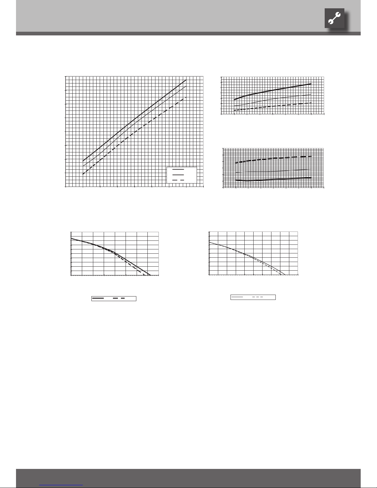
Performance curves SWC 140H(/K)
Legend: UK823000L/170408
“” Volume ow, heating water
“„ Volume ow, heat source
Temp„ Temperature, heat source
Qh Heating capacity
Pe Power consumption
COP Coefcient of performance / efciency rating
∆p” / ∆p”† Free compression, heating circuit / free compression, heating circuit with cooling
∆p„ / ∆p„† Free compression, heat source / free compression, heat source with cooling
Qh (kW)
8
10
12
14
16
18
20
22
24
-10 -5 0 5 10 15 20 25 30
Temp„ (°C)
35°C
50°C
65°C
COP
1
2
3
4
5
6
7
8
-10 -5 0 5 10 15 20 25 30
Temp„ (°C)
Pe (kW)
2
3
4
5
6
7
8
-10 -5 0 5 10 15 20 25 30
Temp„ (°C)
∆p (bar)
0,0
0,1
0,2
0,3
0,4
0,5
0,6
0,7
0,8
0,9
1,0
0,0 0,5 1,0 1,5 2,0 2,5 3,0 3,5 4,0
“”[m3/h]
ǻp” ǻp”†
∆p (bar)
0,0
0,1
0,2
0,3
0,4
0,5
0,6
0,7
0,8
0,9
1,0
0,0 0,5 1,0 1,5 2,0 2,5 3,0 3,5 4,0 4,5 5,0
“„[m3/h]
ǻp„ ǻp„†
Page 34
34
We reserve the right to modify technical specifications without prior notice.
UK830300/170717 © Alpha-InnoTec GmbH
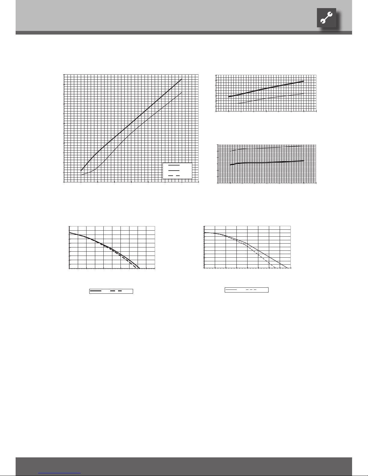
Performance curvesSWC 170H(/K)
Legend: UK823000L/170408
“” Volume ow, heating water
“„ Volume ow, heat source
Temp„ Temperature, heat source
Qh Heating capacity
Pe Power consumption
COP Coefcient of performance / efciency rating
∆p” / ∆p”† Free compression, heating circuit / free compression, heating circuit with cooling
∆p„ / ∆p„† Free compression, heat source / free compression, heat source with cooling
823005
Qh (kW)
12
14
16
18
20
22
24
26
28
30
-10 -5 0 5 10 15 20 25 30
Temp„ (°C)
35°C
50°C
65°C
COP
1
2
3
4
5
6
7
8
-10 -5 0 5 10 15 20 25 30
Temp„ (°C)
Pe (kW)
2
3
4
5
6
7
8
-10 -5 0 5 10 15 20 25 30
Temp„ (°C)
∆p (bar)
0,0
0,1
0,2
0,3
0,4
0,5
0,6
0,7
0,8
0,9
1,0
0,0 0,5 1,0 1,5 2,0 2,5 3,0 3,5 4,0 4,5 5,0
“”[m3/h]
ǻp” ǻp”†
∆p (bar)
0,0
0,1
0,2
0,3
0,4
0,5
0,6
0,7
0,8
0,9
1,0
0,0 0,5 1,0 1,5 2,0 2,5 3,0 3,5 4,0 4,5 5,0
“„[m3/h]
ǻp„ ǻp„†
Page 35
35
We reserve the right to modify technical specifications without prior notice.
UK830300/170717 © Alpha-InnoTec GmbH
Performance curves SWC 230(/K)
Legend: UK823000L/170408
“” Volume ow, heating water
“„ Volume ow, heat source
Temp„ Temperature, heat source
Qh Heating capacity
Pe Power consumption
COP Coefcient of performance / efciency rating
∆p” / ∆p”† Free compression, heating circuit / free compression, heating circuit with cooling
∆p„ / ∆p„† Free compression, heat source / free compression, heat source with cooling
823006
Qh (kW)
16
18
20
22
24
26
28
30
32
34
36
38
-10 -5 0 5 10 15 20 25 30
Temp„ (°C)
35°C
50°C
65°C
COP
1
2
3
4
5
6
7
8
-10 -5 0 5 10 15 20 25 30
Temp„ (°C)
Pe (kW)
2
3
4
5
6
7
8
-10 -5 0 5 10 15 20 25 30
Temp„ (°C)
∆p (bar)
0,0
0,1
0,2
0,3
0,4
0,5
0,6
0,7
0,8
0,9
1,0
0,0 0,5 1,0 1,5 2,0 2,5 3,0 3,5 4,0 4,5 5,0
“”[m3/h]
ǻp” ǻp”†
∆p (bar)
0,0
0,1
0,2
0,3
0,4
0,5
0,6
0,7
0,8
0,9
1,0
1,1
1,2
0,0 1,0 2,0 3,0 4,0 5,0 6,0 7,0 8,0
“„[m3/h]
ǻp„ ǻp„†
Page 36
36
We reserve the right to modify technical specifications without prior notice.
UK830300/170717 © Alpha-InnoTec GmbH
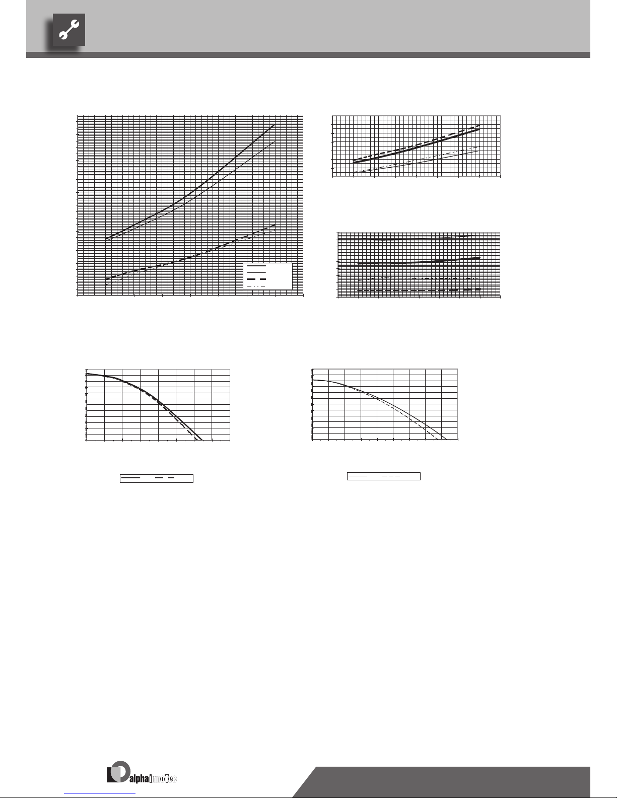
Performance curvesSWC 330(/K)
Legend: UK823000L/170408
“” Volume ow, heating water
“„ Volume ow, heat source
Temp„ Temperature, heat source
Qh Heating capacity
Pe Power consumption
COP Coefcient of performance / efciency rating
∆p” / ∆p”† Free compression, heating circuit / free compression, heating circuit with cooling
∆p„ / ∆p„† Free compression, heat source / free compression, heat source with cooling
VD Condensers
823007
Qh (kW)
10
12
14
16
18
20
22
24
26
28
30
32
34
36
38
40
42
44
46
48
50
52
54
56
58
60
62
64
66
-10 -5 0 5 10 15 20 25 30
Temp„ (°C)
35°C 2VD
50°C 2VD
35°C 1VD
50°C 1VD
COP
2
3
4
5
6
7
8
9
-10 -5 0 5 10 15 20 25 30
Temp„ (°C)
Pe (kW)
3
4
5
6
7
8
9
10
11
12
-10 -5 0 5 10 15 20 25 30
Temp„ (°C)
∆p (bar)
0,0
0,1
0,2
0,3
0,4
0,5
0,6
0,7
0,8
0,9
1,0
1,1
1,2
0,0 1,0 2,0 3,0 4,0 5,0 6,0 7,0 8,0
“”[m3/h]
ǻp” ǻp”†
∆p (bar)
0,0
0,1
0,2
0,3
0,4
0,5
0,6
0,7
0,8
0,9
1,0
1,1
1,2
0,0 1,0 2,0 3,0 4,0 5,0 6,0 7,0 8,0 9,0
“„[m3/h]
ǻp„ ǻp„†
Page 37

37
We reserve the right to modify technical specifications without prior notice.
UK830300/170717 © Alpha-InnoTec GmbH
Page 38
38
We reserve the right to modify technical specifications without prior notice.
UK830300/170717 © Alpha-InnoTec GmbH
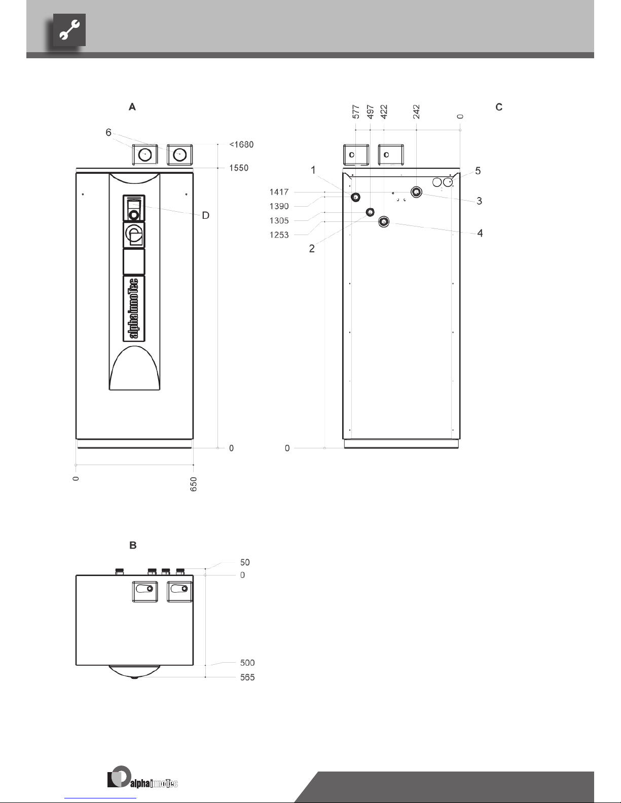
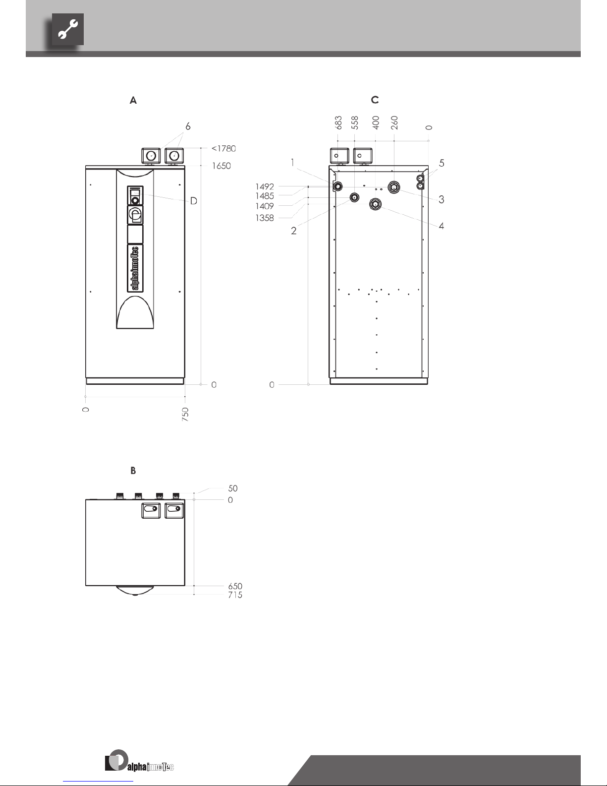
Size 1: Dimensional drawings
Legend: UK819248a
All dimensions in mm.
A Front view
B Top view
C Rear view
D Control element
1 Heating water outow (forward ow) DIN ISO 228
SWC 60… to SWC 100…: G1"AG
SWC120… to SWC 170…: G1¼"AG
2 Heating water inow (return ow) DIN ISO 228
SWC 60… to SWC 100…: G1"AG
SWC120… to SWC 170…: G1¼"AG
3 Heat source inow (return ow) DIN ISO 228
SWC 60… to SWC 100…: G1"AG
SWC120… to SWC 170…: G1¼"AG
4 Heat source outow (forward ow) DIN ISO 228
SWC 60… to SWC 100…: G1"AG
SWC120… to SWC 170…: G1¼"AG
5 Ducts for electric/sensor cables
6 Safety components
Page 39
39
We reserve the right to modify technical specifications without prior notice.
UK830300/170717 © Alpha-InnoTec GmbH
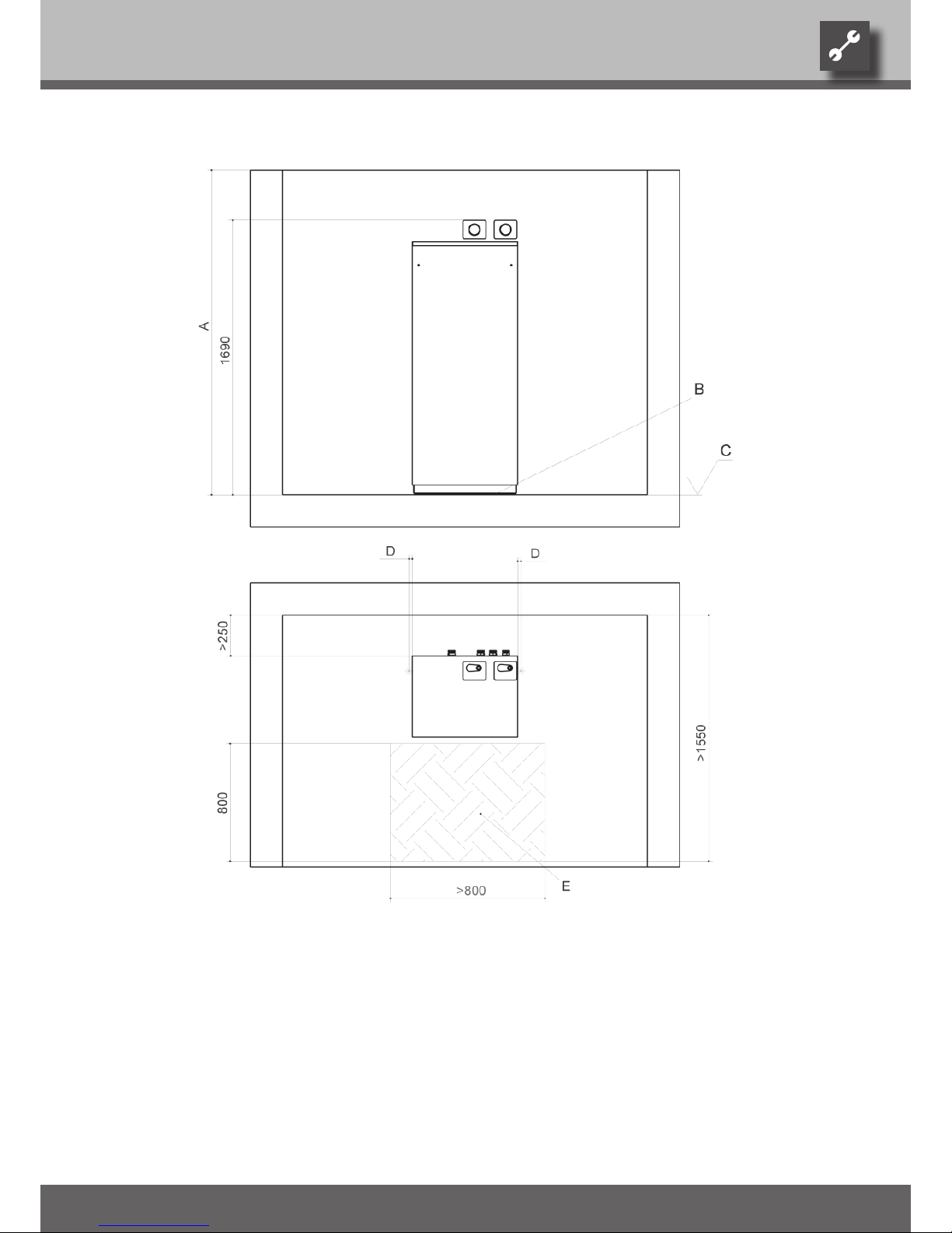
Size 1: Clearance dimensions
Legend: UK819252b
All dimensions in mm.
A Room height ≥ 2000
B Unit installation on sylomer strips
C Top edge of nished oor
D Distance to next lateral object ≥ 20
E Shaded area = free space for service purposes
Page 40
40
We reserve the right to modify technical specifications without prior notice.
UK830300/170717 © Alpha-InnoTec GmbH
Size 2: Dimensional drawings
Legend: UK819253a
All dimensions in mm.
A Front view
B Top view
C Rear view
D Control element
1 Heating water outow (forward ow) DIN 2999 R1½"AG
2 Heating water inow (return ow) DIN 2999 R1½"AG
3 Heat source inow (return ow) DIN 2999 R1½"AG
4 Heat source outow (forward ow) DIN 2999 R1½"AG
5 Ducts for electric/sensor cables
6 Safety components
Attention! Included in scope of delivery:
4 x compensator DN 40, Rp 1½"IG DIN 2999
Page 41
41
We reserve the right to modify technical specifications without prior notice.
UK830300/170717 © Alpha-InnoTec GmbH
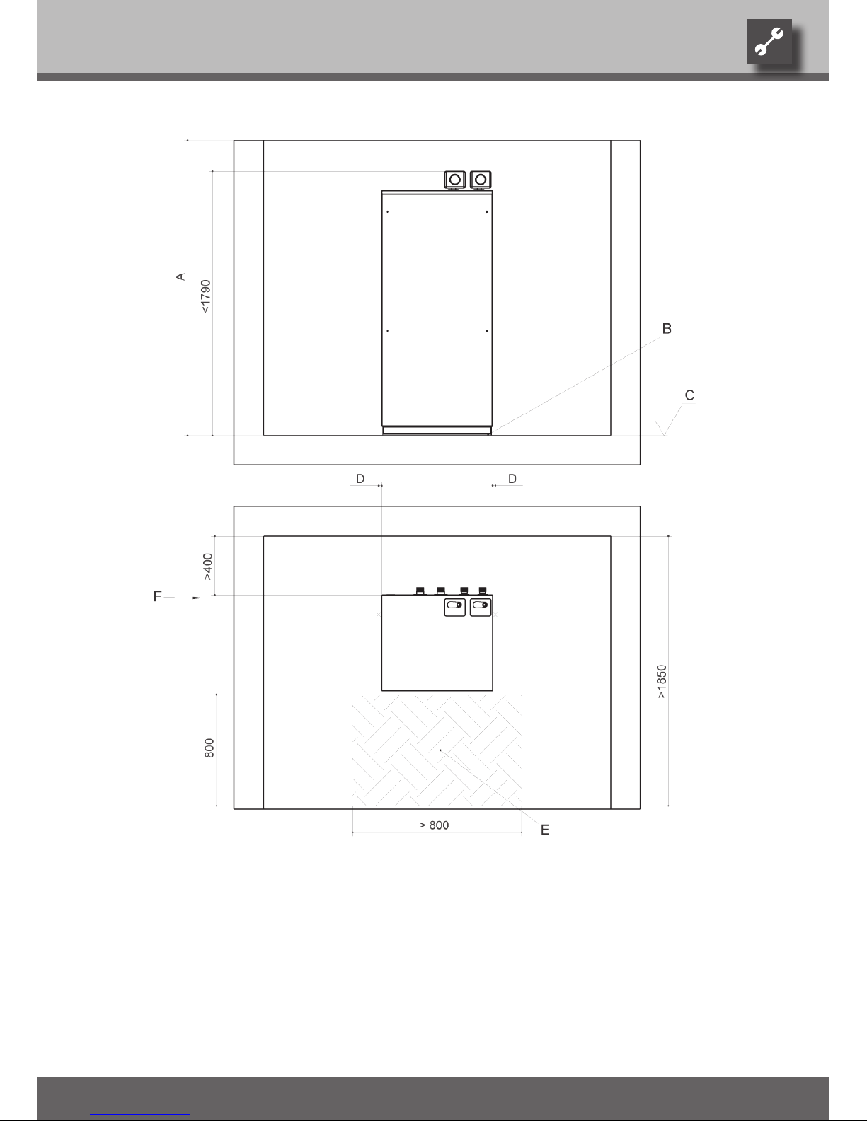
Size 2: Clearance dimensions
Legend: UK819255b
All dimensions in mm.
A Room height ≥ 2000
B Unit installation on sylomer strips
C Top edge of nished oor
D Distance to next lateral object ≥ 20
E Shaded area = free space for service purposes
F In the event of offset mounting of the compensators the dimension 400 can be
reduced to ≥ 250.
The bracket must be provided by the customer.
Page 42
42
We reserve the right to modify technical specifications without prior notice.
UK830300/170717 © Alpha-InnoTec GmbH
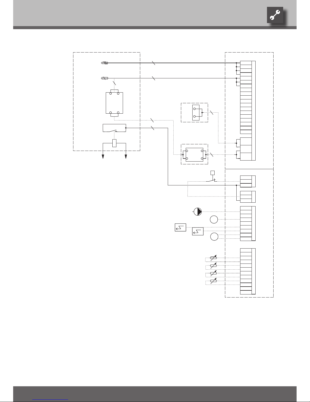
-F12 -F10 -F11
L Y2
A1
A2
4
1
5
2
P
3~PE/400V/50Hz
ASD
MOT
2
2
Charge/discharge/cooling mixer 1 closed
PEX
Accessories: Remote control
PE
-X4
PE
MIS
TB1
TA
External return sensor
MZ1/MIS
Sensor mixing circuit 1
no function
6-12 kW: C10 A
14-17 kW: C16 A14-17 kW: C16 A
3
Charge/discharge/cooling mixer 1 open
-X7
Overload protection; internally wired
EVU
TRL
HUP
TB1
L1
TB1
TA
GND
GND
Pump for mixing circuit 1
N
N
ASD
EVU
ASD
TRL
MA1/MIS
MZ1
4
Brine pressure pressostat; provided by cust. if necessary
External sensor
PE
ZW1
GND
Accessories: Transformer for dewpoint monitorL1Accessories with cooling option: Dewpoint monitor; bridge if not connected
1~N/PE/230V/50Hz
PE
RFV
UK831120a
L1
Energy supplier contact; closed on release; bridge if no blocking interval
B10 A
F10
GND
FP1
L2
Controller board; Attention: I-max = 6A/230VAC
Cut out controller unit
6-12 kW: C10 A
14-17 kW: C16 A14-17 kW: C16 A
RFV
PE
M
PEX
N
FP1
N
PE
A2
With cooling option: Room thermostat; bridge if not connected
Y3
GND
RFV
3-pol. Cut out compressor; Attention: Right-hand rot. field is mandatory!
Terminals in heat pump switchbox
BUP
Legend:
Function
Accessories: Process water sensor/thermostat
ZW1
VBO
VBO
Terminals
Control signal of additional heat generator 2 (alternative is general malfunction)
Control signal of additional heat generator 1; internally wired
-X0
Power supply compressor 3 x 400V; Attention: Right-hand rot. field is mandatory!
ZUP/ZIP
Y2
A2
M
Terminal strips on controller board (see sticker)
F11
T2
ZW2/SST
-X3
MA1
L3
Control 230V
X7:PE,L1,L2,L3
24V
-Y2
X7:PE,N,L1
230V
1
-Y3
3~N/PE/400V/50Hz
-T2
3
2
Auxiliary circulation pump / circulation pump
Brine water compact 6 - 17 kW
2
X7:PE,N,L1,L2,L3
X7
Auxiliary heating 3 x 400V2Brine circulation pump
Terminal strip in switchbox of heat pump; N/PE distribution for external 230V units
6 - 17 kW
X0-X4
TBW
EVU
Heating circuit circulation pump; internally wired
TBW
N
L2
L1
ZW2/SST
-X2
Sub-distribution unit internal installation
L1
BUP
HUP
BUP
FP1
N
GND
ZW1
TA
PE
Cut out auxiliary heating
5
MOT
A3
Accessories: Process water for changeover valve
L3
A1
ZW2/SST
A3
PE
N
2
F12
A1
PE
ZUP/ZIP
L1
Name
N
TBW
1 2 3 4 5 6 7 8 9 10 11 12 13 14 15 16
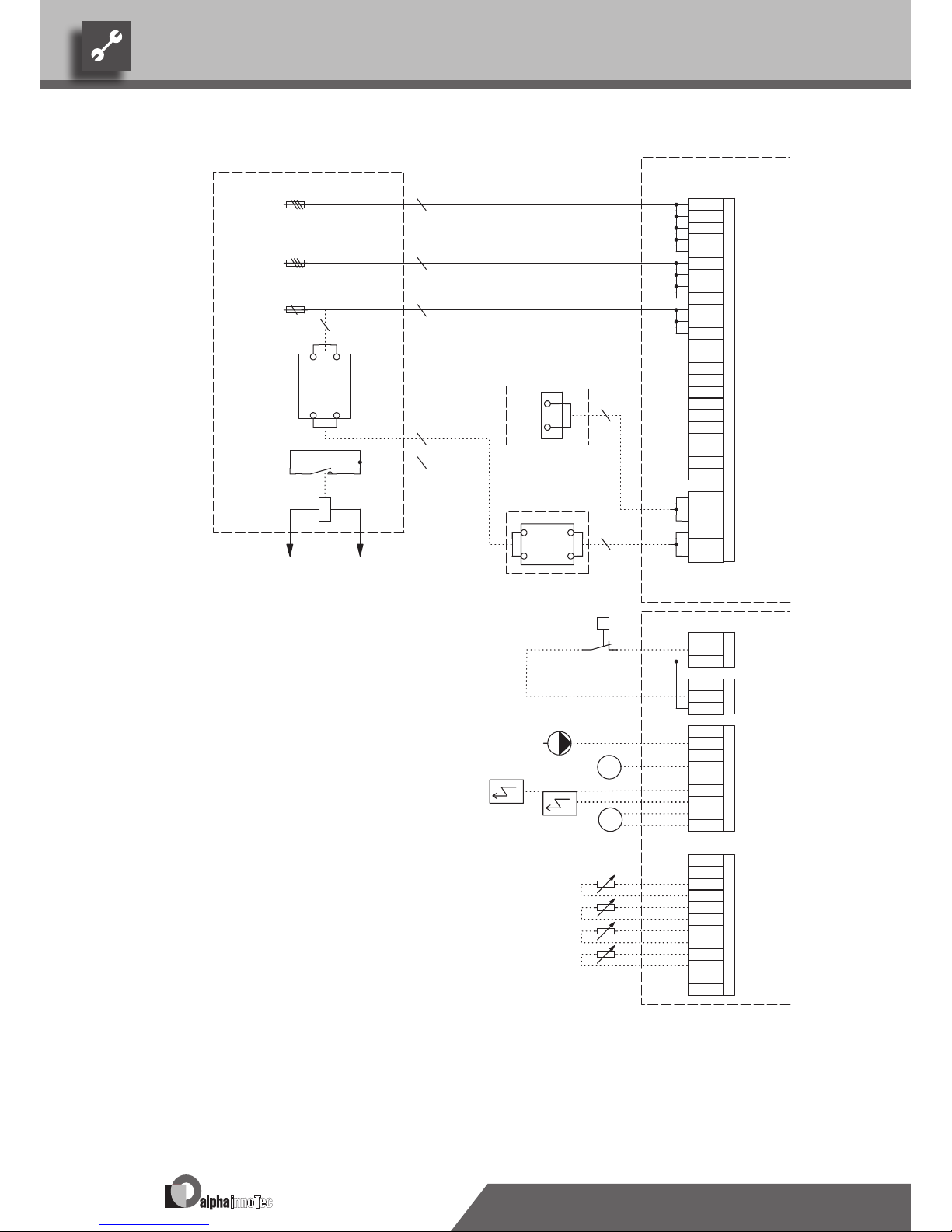
Terminal diagramSWC 60H(/K) – SWC 170H(/K)
Page 43
43
We reserve the right to modify technical specifications without prior notice.
UK830300/170717 © Alpha-InnoTec GmbH
Terminal diagram SWC 230(/K) – SWC 330(/K)
-F10 -F11
L Y2
A1
A2
4
1
5
2
P
Brine water compact 23 - 33 kW
L1
N
3
230V
ASD
-X2
TBW
A3
L1
BUP
TB1
GND
MZ1
2
N
-X0
TA
PE
L1
2
N
MA1
2
ZW2/SST
A2
FP1
N
TBW
EVU
N
1
PE
RFV
-T2
2
L1
4
L1
2
-X4-X3
EVU
MOT
PE
2
PE
ASD
VBO
A1
TA
-Y3
PE
GND
TRL
ZW1
24V
TB1
L3
MIS
PEX
ZW2/SST
M
GND
L2
HUP
GND
3
B10 A
BUP
ZW1
PE
-Y2
M
FP1
23kW: C16 A
33kW: C25 A33kW: C25 A
Terminal strip in switchbox of heat pump; N/PE distribution for external 230V units
Control signal of additional heat generator 1
X7:PE,N,L1
3~PE/400V/50Hz
Control signal of additional heat generator 2 (alternative is general malfunction)
Power supply compressor 3 x 400V; Attention: Right-hand rot. field is mandatory!
Control 230V
X0-X4
ZUP/ZIP
Terminal strips on controller board (see sticker)
Charge/discharge/cooling mixer 1 closed
Auxiliary circulation pump / circulation pump
Accessories: Remote control
TA
ZW2/SST
X7
Brine circulation pump
ZW1
X7:PE,L1,L2,L3
TBW
HUP
Name
A1
Heating circuit circulation pump; internally wired
ASD
23 - 33 kW
Accessories: Process water sensor/thermostat
Brine pressure pressostat; provided by cust. if necessary
A2
Y2
VBO
Terminals
A3
F11
Accessories: Process water for changeover valve
T2
Sub-distribution unit internal installation
TB1
Charge/discharge/cooling mixer 1 open
-X7
Cut out controller unit
Accessories with cooling option: Dewpoint monitor; bridge if not connected
Energy supplier contact; closed on release; bridge if no blocking interval
UK831122a
Accessories: Transformer for dewpoint monitor
With cooling option: Room thermostat; bridge if not connected
N
Legend:
F10
GND
GND
1~N/PE/230V/50Hz
RFV
N
PE
PE
BUP
ZUP/ZIP
MZ1/MIS
no function
TRL
MA1/MIS
Overload protection; internally wired
PEX
Controller board; Attention: I-max = 6A/230VAC
FP1
MOT
External sensor
Y3
Terminals in heat pump switchbox
Pump for mixing circuit 1
Function
3-pol. Cut out compressor; Attention: Right-hand rot. field is mandatory!
Sensor mixing circuit 1
External return sensor
EVU
RFV
1 2 3 4 5 6 7 8 9 10 11 12 13 14 15 16
Page 44
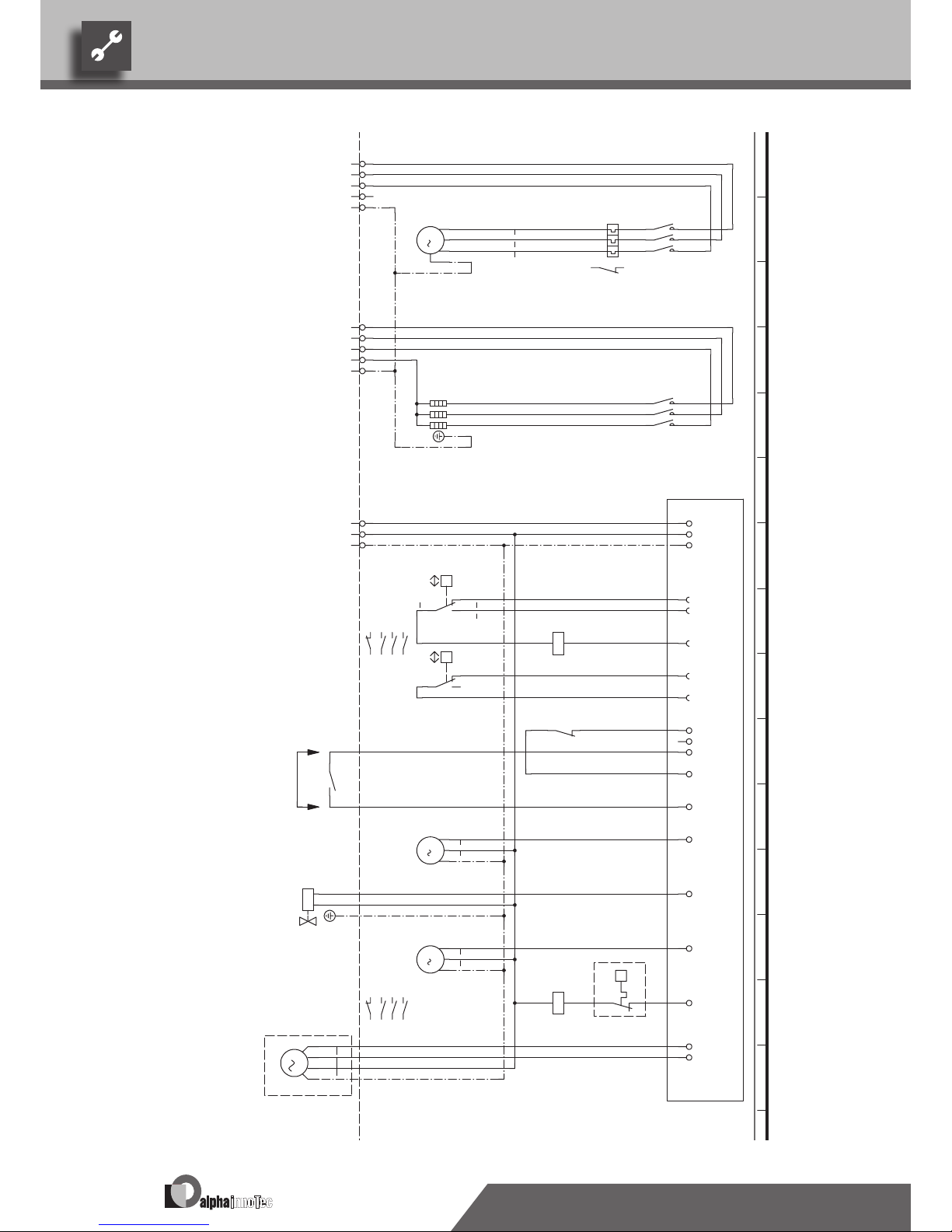
44
We reserve the right to modify technical specifications without prior notice.
UK830300/170717 © Alpha-InnoTec GmbH
Circuit diagram 1/2SWC 60H(/K) – SWC 80H(/K)
L1
-X7
L2 L3 N PE
1
2
-K1
8
3
4
1
3 5
2 4 6
-F4
M
3
T1
T2
T3
PE
-M1
VD1
5
6
L1
-X7
L2 L3 N PE
1
2
-K5
14
3
4
5
6
L
-X0
L
-X7
N
N
PE
PE
N..
-X1
P
+-
b2 c 4
a1
-F1
HDP
HD.
1 223 425 6
2
21 22
VD1
-X1
A1
A2
-K1
ND.
-X1
P
- +
c4 b2
a1
-F2
NDP
L..
L
-X0
95
96
-F4
2
L L
MOT
-X2
EVU
-X2
HUP
-X3
M
1
L
N
PE
-M4
BUP
-X3
1 2
-Y1
VBO
-X3
M
1
L
N
PE
-M3
1 253 455 6
5
21 22
ZW1
-X3
-
-STB
A1
A2
-K5
ZW1
MA1
-X3
MZ1
M
1
A
Z
N
PE
-M16
MIS
9596
10
K5
HDP
VD1
UK817250b
Heating circulation pump
MISF1HUP
3
3
2
3~N/PE/400V/50Hz
1~N/PE/230V/50Hz
Power supply compressor; right-hand rot. field is mandatory!
1
3~N/PE/400V/50Hz
Contactor for auxiliary heating
s
wbr
1
M16
Power supply aux. heating
High-pressure switch
ZW1
230VAC
Legend:
K1
M4
Mixer; installed with cooling option
2
bl
Contactor for compressor 1
-A1
3~PE/400V/50Hz
VD1
Energy supplier contact; closed on release; bridge if no blocking interval
R1
M3
Compressor 1
Auxiliary heating
M1
ZW1
STB
Accessories: Process water for changeover valve
Low-pressure switch
Y1
Terminal strip in switchbox of heat pump; N/PE distribution for external 230V units
Safety temperature limiter heating element
BUP
X7
BOSUP
Operating materials
EVU
3~PE/400V/50Hz
-R1
Controller supply
Function
1
2
Controller board; Attention: I-max = 6A/230VAC
F2
1
2
A1
NDP
Brine pump
1~N/PE/230V/50Hz
EVU
1 2 3 4 5 6 7 8 9 10 11 12 13 14 15 16
Page 45
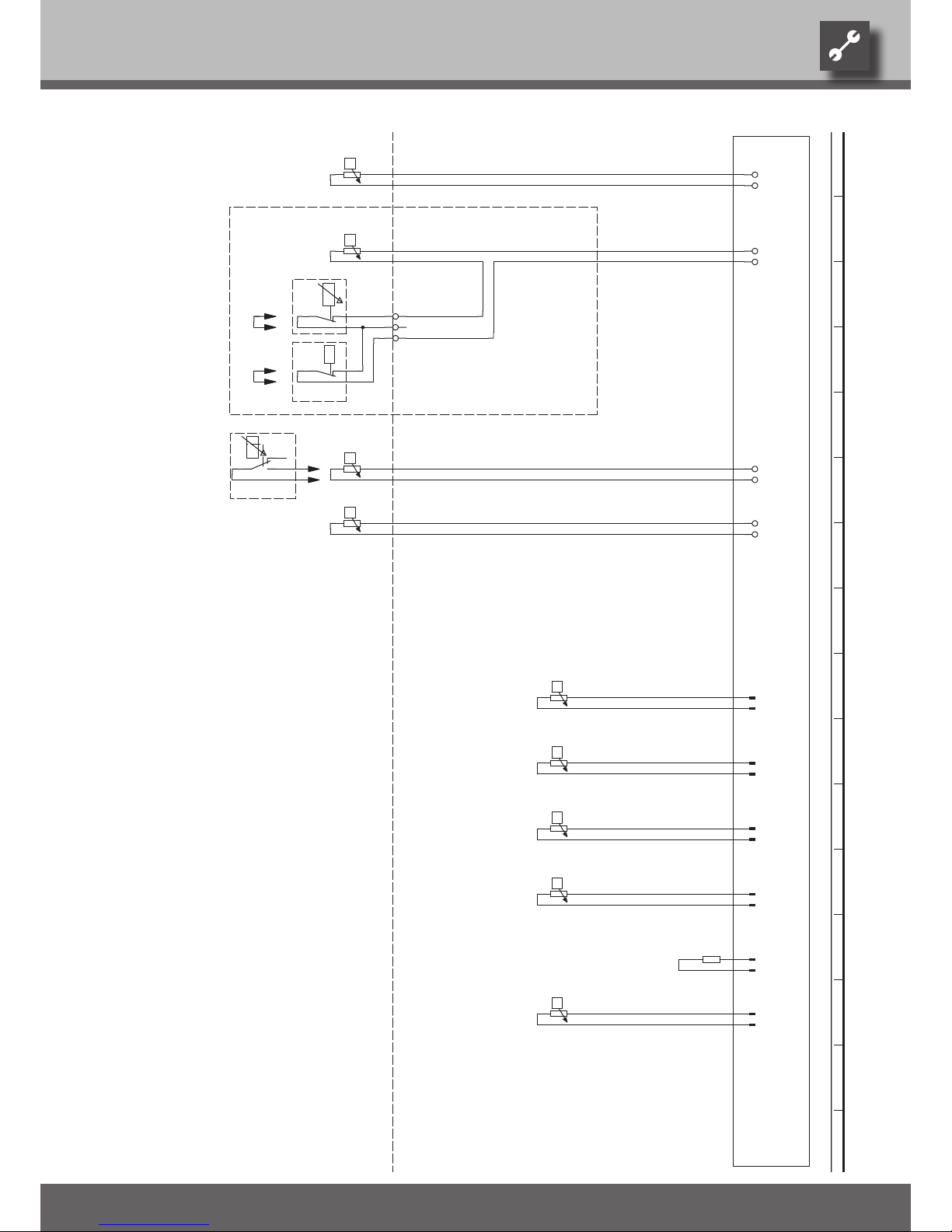
45
We reserve the right to modify technical specifications without prior notice.
UK830300/170717 © Alpha-InnoTec GmbH
-
RFV
-X4
-R10
RFV
GND
-
TB1
-X4
-R13
TB1
GND
TR
1
-X7
2 3
TR
-
TBW
-X4
-R9
TBW
GND
-
TA.
-X4
-R8
TA
GND
-
TRL
-X5
-R4
TRL
GND
-
TVL
-X5
-R5
TVL
GND
-
THG
-X5
-R6
THG
GND
-
TWA
-X5
-R11
TWA
GND
CW.
-X5
-R12
GND
-
TWE
-X5
-R7
TWE
GND
BWT Accessories: Process water for thermostat
Heat pump coding; SWC - 875 ohm
R10
Sensor mixing circuit 1; installed with cooling optionY2Domestic hot water sensor
R12
R13Y4R11
Flow sensorR5
Function
-Y2
4
-Y3
L
-Y2
-CW
-Y3
-A1
Y2
Heat source input sensor
5
BWT
-Y4
CW
Return sensor
Hot gas sensor
Controller board; Attention: I-max = 6A/230VAC
Legend:
R9
TB1
TVL
TWE
TBW
UK817250b
RFV
THG
TWA
A1
Y3
Heat source output sensor
Accessories: Remote control
R8
TRL
External sensor
R7
With cooling option: Room thermostat; bridge if not connected
Accessories with cooling option: Dewpoint monitor; bridge if not connected
TA
Operating materialsR6R4
1 2 3 4 5 6 7 8 9 10 11 12 13 14 15 16
Circuit diagram 2/2 SWC 60H(/K) – SWC 80H(/K)
Page 46
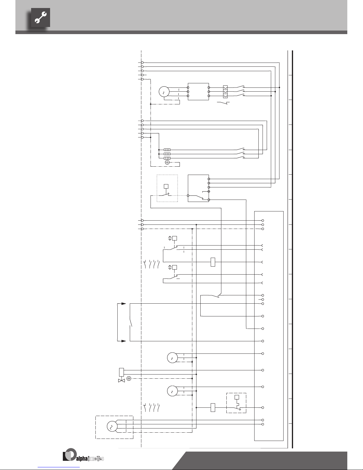
46
We reserve the right to modify technical specifications without prior notice.
UK830300/170717 © Alpha-InnoTec GmbH
Circuit diagram 1/2SWC 100H(/K) – SWC 170H(/K)
L1
-X7
L2 L3 N PE
1
2
-K1
9
3
4
1
3 5
2 4 6
-F4
R S T
U V W
-N1
M
3
T1
T2
T3
PE
-M1
VD1
5
6
L1
-X7
L2 L3 N PE
1
2
-K5
15
3
4
5
6
L1 L2 L3 12 14
11
-B1
P-F20
L
-X0
L
-X7
N
N
PE
PE
N..
-X1
P
+-
b2 c 4
a1
-F1
HDP
HD.
1 223 425 6
2
21
VD1
-X1
A1
A2
-K1
ND.
-X1
P
- +
c4 b2
a1
-F2
NDP
L..
L
-X0
95
96
-F4
2
L L
MOT
-X2
ASD
-X2
EVU
-X2
HUP
-X3
M
1
L N PE
-M4
BUP
-X3
1 2
-Y1
VBO
-X3
M
1
L N PE
-M3
1 253 455 6
5
21
ZW1
-X3
-
-STB
A1
A2
-K5
ZW1
MA1
-X3
MZ1
M
1
A
Z
N
PE
-M16
MIS
9596
10
EVU
Phase sequence relay; if phase sequence in the order of 11 + 14 is closed
Overload relay for compressor 1
F2
1~N/PE/230V/50Hz Controller supply
Controller board; Attention: I-max = 6A/230VAC
Function
3~N/PE/400V/50Hz
2
Legend:
b
r
2
3~N/PE/400V/50Hz
3
-A1
F1
F4
1
Low-pressure switch
1
NDP
EVU
HDP
Energy supplier contact; closed on release; bridge if no blocking interval
1~N/PE/230V/50Hz
Power supply aux. heating
2
sw
3~PE/400V/50Hz
1
High-pressure switch
B1
-R1
Contactor for auxiliary heating
230VAC
A1
2
Brine pump
VD1
M16
K5
K1
Compressor 1
BUP
VD1
Terminal strip in switchbox of heat pump; N/PE distribution for external 230V units
Contactor for compressor 1
UK817251c
N1
F20 Brine pressure pressostat; provided by cust. if necessary
Heating circulation pump
Mixer; installed with cooling option
ZW1
Starting current limit
MIS
R1
M4
BOSUP
STB
3
Operating materials
b
l
1
Power supply compressor; right-hand rot. field is mandatory!
M3
ZW1
Safety temperature limiter heating element
Accessories: Process water for changeover valve
HUP
3~PE/400V/50Hz
Y1M1X7
Auxiliary heating
1 2 3 4 5 6 7 8 9 10 11 12 13 14 15 16
Page 47
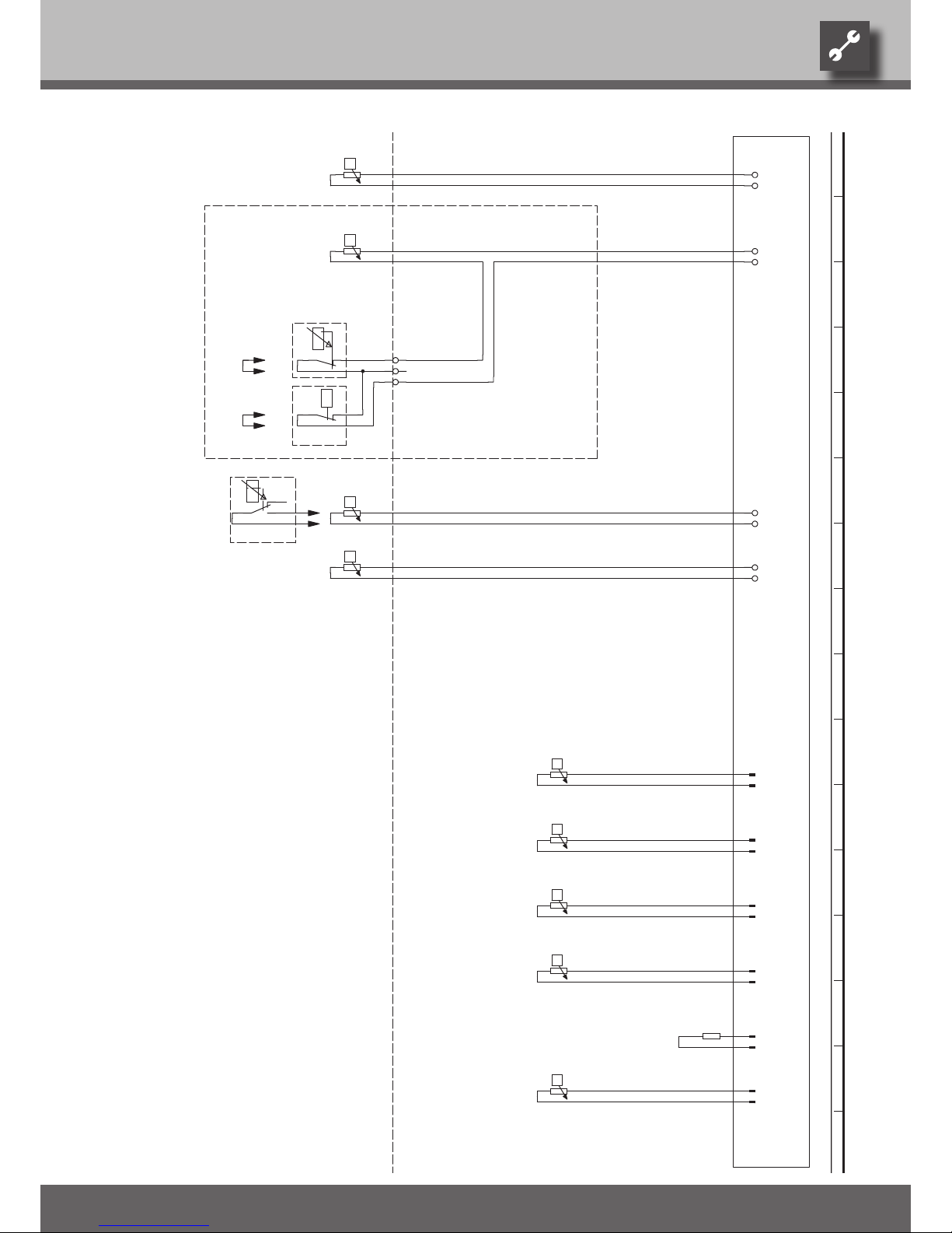
47
We reserve the right to modify technical specifications without prior notice.
UK830300/170717 © Alpha-InnoTec GmbH
-
RFV
-X4
-R10
RFV
GND
-
TB1
-X4
-R13
TB1
GND
TR
1
-X7
2 3
TR
-
TBW
-X4
-R9
TBW
GND
-
TA.
-X4
-R8
TA
GND
-
TRL
-X5
-R4
TRL
GND
-
TVL
-X5
-R5
TVL
GND
-
THG
-X5
-R6
THG
GND
-
TWA
-X5
-R11
TWA
GND
CW.
-X5
-R12
GND
-
TWE
-X5
-R7
TWE
GND
UK817251c
THG
TWA
RFV
TBW
TVL
TA
Hot gas sensor
Domestic hot water sensor
TWE
Return sensor
Sensor mixing circuit 1; installed with cooling option
Heat source input sensor
R12
R9
Heat pump coding; SWC - 845 ohm
Flow sensor
R10R5R6
R4
Accessories: Process water for thermostat
With cooling option: Room thermostat; bridge if not connected
Accessories: Remote control
R7
Accessories with cooling option: Dewpoint monitor; bridge if not connected
Heat source output sensorR11
Y2
A1
5
R13
-Y4
CW
External sensor
TB1
-Y2
BWT
4
Y2
-A1
Y4
R8
L
-Y2
Legend:
-Y3
BWT
-CW
FunctionOperating materials
Y3
TRL
Controller board; Attention: I-max = 6A/230VAC
-Y3
1 2 3 4 5 6 7 8 9 10 11 12 13 14 15 16
Circuit diagram 2/2 SWC 100H(/K) – SWC 170H(/K)
Page 48
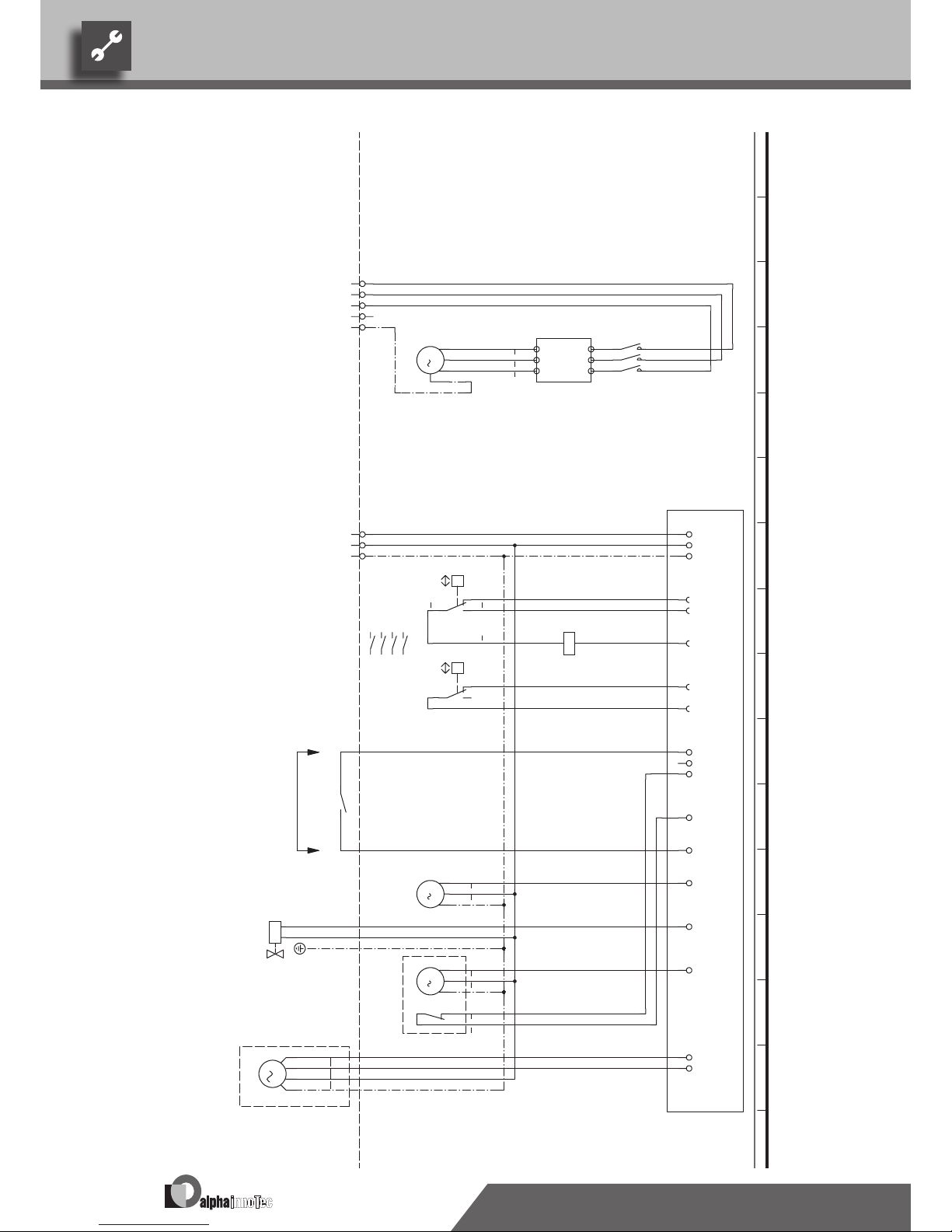
48
We reserve the right to modify technical specifications without prior notice.
UK830300/170717 © Alpha-InnoTec GmbH
Circuit diagram 1/2
SWC 230(/K)
L1
-X7
L2 L3 N PE
1
2
-K1
8
3
4
R S T
U V W
-N1
M
3
T1
T2
T3
PE
-M1
VD1
5
6
L
-X0
L
-X7
N
N
PE
PE
N..
-X1
P
+-
b2 c 4
a1
-F1
HDP
HD.
1 243 445 6
4
13 14
VD1
-X1
A1
A2
-K1
VD1
ND.
-X1
P
- +
c4 b2
a1
-F2
NDP
L..
L
-X0
L L
MOT
-X2
EVU
-X2
HUP
-X3
M
1
L
N
PE
-M4
BUP
-X3
1 2
-Y1
VBO
-X3
M
1
L
N
PE
-M3
MA1
-X3
MZ1
M
1
A
Z
N
PE
-M16
MIS
3~PE/400V/50Hz
F1
b
l
Starting current limit
-A1
High-pressure switch
Function
3~PE/400V/50Hz
4
F2
3
EVU
1
3
2
NDP
A1
Controller supply
EVU
2
M16 Mixer; installed with cooling option
Operating materials
1~N/PE/230V/50Hz
Controller board; Attention: I-max = 6A/230VAC
b
r
Low-pressure switch1Energy supplier contact; closed on release; bridge if no blocking interval
HDP
1
230VAC
M4
BOSUPM3
VD1 Contactor for compressor 1
M1
Power supply compressor; right-hand rot. field is mandatory!
Brine pump
2
WSK
Compressor 1VD1
K1
MIS
Heating circulation pump
1~N/PE/230V/50Hz
sw
HUP
Legend:
3
21
N1
Pump thermocontact
Terminal strip in switchbox of heat pump; N/PE distribution for external 230V units
Y1X7WSK
BUP Accessories: Process water for changeover valve
UK817252b
1 2 3 4 5 6 7 8 9 10 11 12 13 14 15 16
Page 49
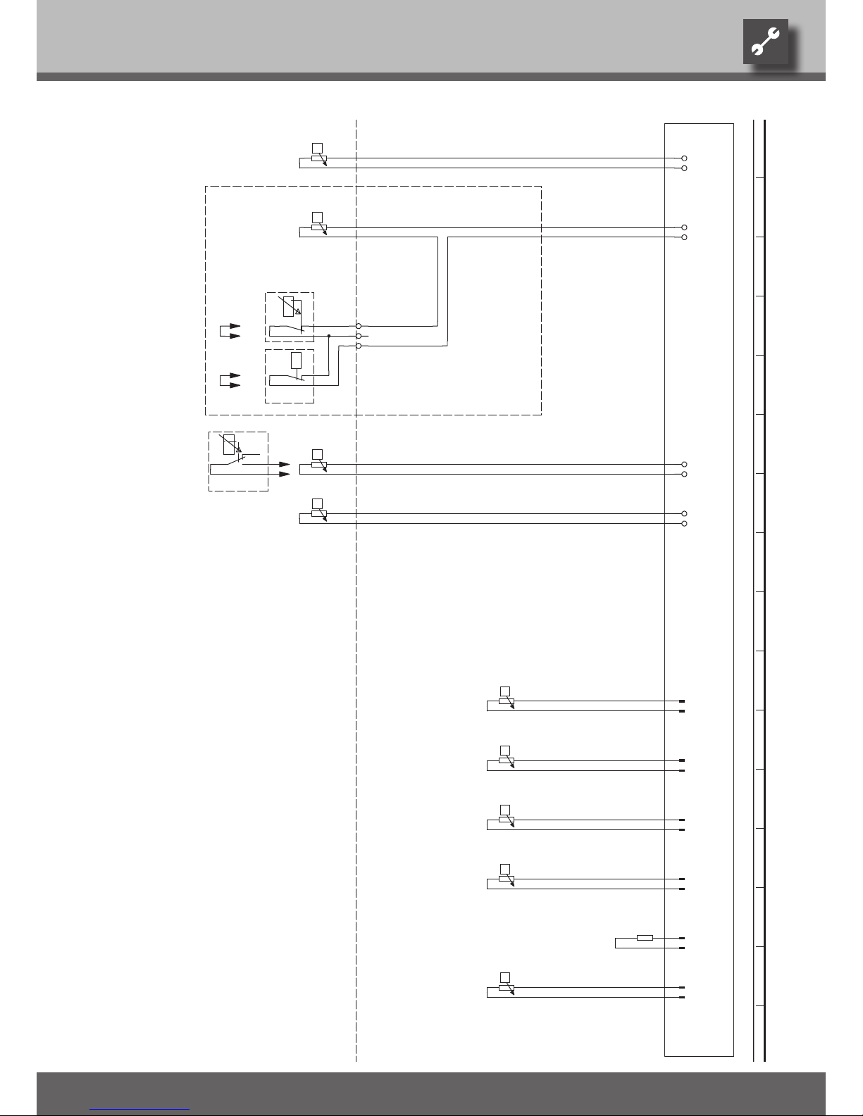
49
We reserve the right to modify technical specifications without prior notice.
UK830300/170717 © Alpha-InnoTec GmbH
-
RFV
-X4
-R10
RFV
GND
-
TB1
-X4
-R13
TB1
GND
TR
1
-X7
2 3
TR
-
TBW
-X4
-R9
TBW
GND
-
TA.
-X4
-R8
TA
GND
-
TRL
-X5
-R4
TRL
GND
-
TVL
-X5
-R5
TVL
GND
-
THG
-X5
-R6
THG
GND
-
TWA
-X5
-R11
TWA
GND
CW.
-X5
-R12
GND
-
TWE
-X5
-R7
TWE
GND
UK817252b
TB1
-A1
5
4
External sensor
-Y2
-Y4
Y2
CW
Return sensor
R13
Y4
A1
Y2
Y3
Operating materials Function
-Y3
Controller board; Attention: I-max = 6A/230VAC per contact
TRL
-CW
-Y2
L
R8
BWT
-Y3
Legend:
Domestic hot water sensor
R12
RFV
Sensor mixing circuit 1; installed with cooling option
Hot gas sensor
TWE
TVL
THG
TA
BWT
TBWR9TWA
Heat source input sensorR7
Accessories: Remote control
With cooling option: Room thermostat; bridge if not connected
R11 Heat source output sensor
Accessories with cooling option: Dewpoint monitor; bridge if not connected
Accessories: Process water for thermostat
R10
Flow sensor
Heat pump coding; SWC - 845 ohm
R4R6R5
1 2 3 4 5 6 7 8 9 10 11 12 13 14 15 16
Circuit diagram 2/2 SWC 230(/K)
Page 50
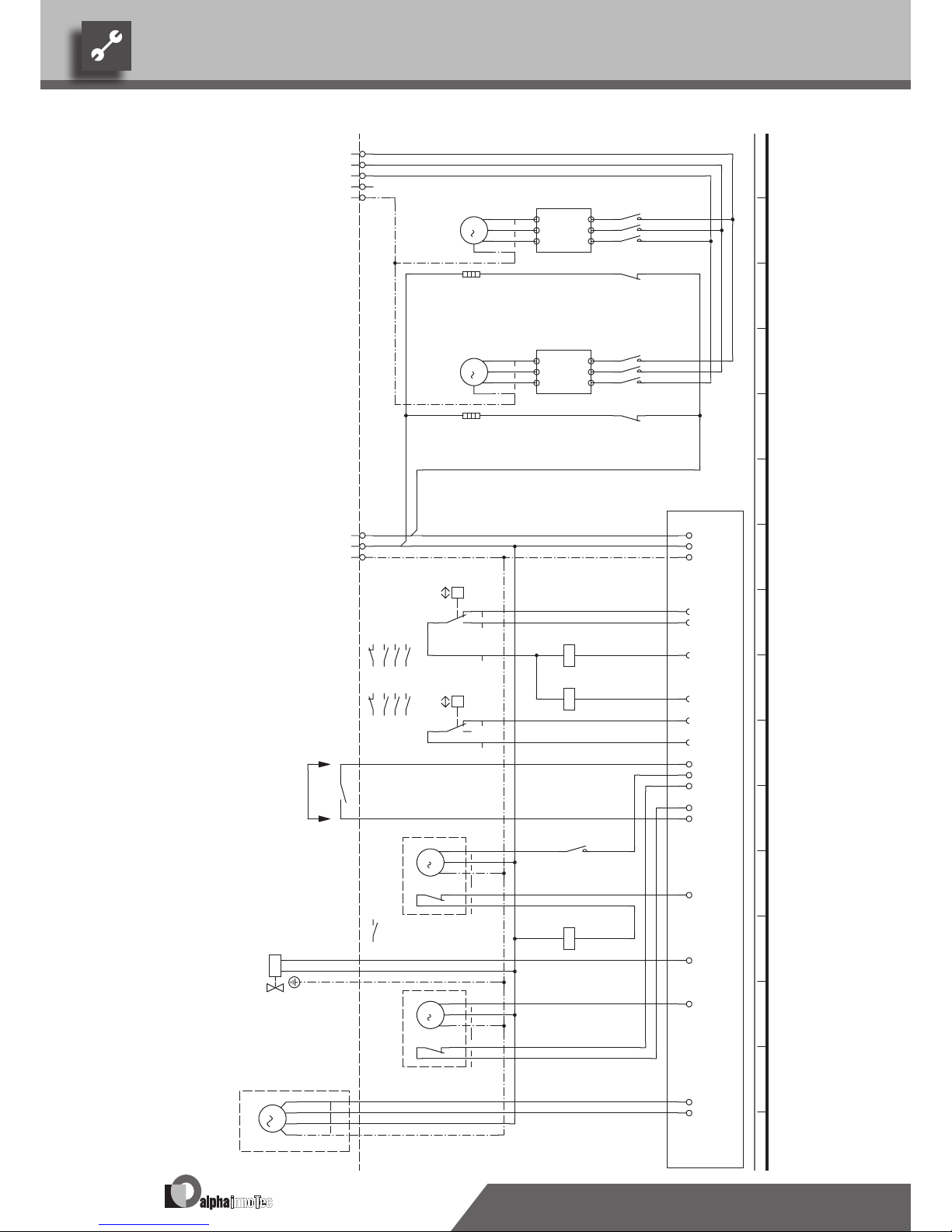
50
We reserve the right to modify technical specifications without prior notice.
UK830300/170717 © Alpha-InnoTec GmbH
Circuit diagram 1/2SWC 330(/K)
L1
-X7
L2 L3 N PE
1
2
-K1
9
3
4
R S T
U V W
-N1
M
3
T1 T2 T3 PE
-M1
VD1
5
6
11
12
-K1
9
-R20
1
2
-K2
9
3
4
R S T
U V W
-N2
M
3
T1 T2 T3 PE
-M2
VD2
5
6
11
12
-K2
9
-R21
L
-X0
L
-X7
N
N
PE
PE
N..
-X1
P
+-
b2 c4
a1
-F1
HDP
HD.
VD1
-X1
A1
A2
-K1
VD1
VD2
-X1
A1
A2
-K2
VD2
ND.
P
- +
c4 b2
a1
-F2
NDP
L..
L
-X0
L L
MOT
-X2
EVU
11
14
-K6
13
M
1
L
N
PE
-M4
HUP
-X3
A1
A2
-K6
BUP
-X3
1 2
-Y1
VBO
-X3
M
1
L
N
PE
-M3
MA1
-X3
MZ1
M
1
A
Z
N
PE
-M16
MIS
11 14
12
1 243 445 6
4
11
5
1 223 425 6
2
11
3
PE
VD2M2
1
Brine pump
Operating materials
WSK
3
M16
Sump heating for compressor 2
Compressor 2
BUP
Pump thermocontact
Terminal strip in switchbox of heat pump; N/PE distribution for external 230V units
Accessories: Process water for changeover valveY1
4
VD1
Starting current limit compressor 2
WSK
X7
Compressor 1
WSK
1~N/PE/230V/50Hz
sw
Starting current limit compressor 1
N2
M3
Legend:
Contactor for thermo contact on heating circulation pump
A1
2
M4
Sump heating for compressor 1
HUP Heating circulation pump
K6
N1
Mixer; installed with cooling optionMIS
BOSUP
R20
M1
UK817253d
EVU
1
Low-pressure switchNDP
-A1
Function
3~PE/400V/50Hz
2
HDPF1
3
230VAC
2
Controller board; Attention: I-max = 6A/230VAC
1
2
br
VD2
2
Contactor for compressor 2
4
bl
3~PE/400V/50Hz
VD1
High-pressure switch
F2
1~N/PE/230V/50Hz
R21
K1
Power supply compressor; right-hand rot. field is mandatory!
Energy supplier contact; closed on release; bridge if no blocking interval
Controller supply
1
3 PE
3
EVU
1
Contactor for compressor 1
3
12
K2
1 2 3 4 5 6 7 8 9 10 11 12 13 14 15 16
Page 51
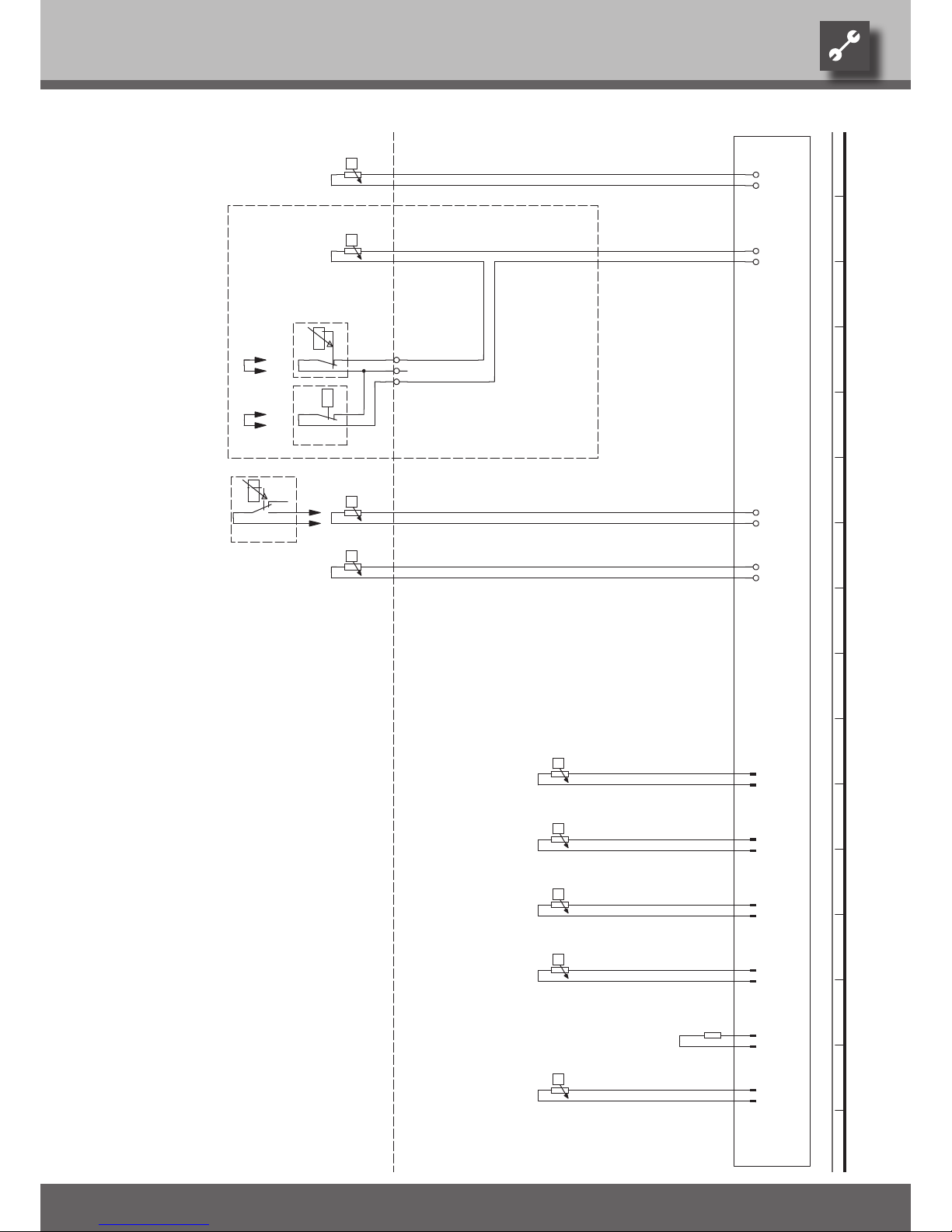
51
We reserve the right to modify technical specifications without prior notice.
UK830300/170717 © Alpha-InnoTec GmbH
-
RFV
-X4
-R10
RFV
GND
-
TB1
-X4
-R13
TB1
GND
TR
1
-X7
2 3
TR
-
TBW
-X4
-R9
TBW
GND
-
TA.
-X4
-R8
TA
GND
-
TRL
-X5
-R4
TRL
GND
-
TVL
-X5
-R5
TVL
GND
-
THG
-X5
-R6
THG
GND
-
TWA
-X5
-R11
TWA
GND
CW.
-X5
-R12
GND
-
TWE
-X5
-R7
TWE
GND
UK817253d
BWT
TA
THG
TWAR9TBW
TVL
RFV
R12
Domestic hot water sensor
TWE
Hot gas sensor
Sensor mixing circuit 1; installed with cooling option
Heat source input sensor
Heat pump coding; SW2 - 160 ohm
Flow sensor
R10R5R6
R4
Accessories: Process water for thermostat
With cooling option: Room thermostat; bridge if not connected
Accessories: Remote control
R7
Accessories with cooling option: Dewpoint monitor; bridge if not connected
Heat source output sensorR11
Return sensor
CW
Y2A1Y4
R13
-Y4
5
-A1
TB1
-Y2
External sensor
4
Y2
R8
L
-Y2
Legend:
-Y3
BWT
-CW
FunctionOperating materials
Y3
TRL
Controller board; Attention: I-max = 6A/230VAC
-Y3
1 2 3 4 5 6 7 8 9 10 11 12 13 14 15 16
Circuit diagram 2/2 SWC 330(/K)
Page 52

52
We reserve the right to modify technical specifications without prior notice.
UK830300/170717 © Alpha-InnoTec GmbH
The undersigned
confirms that the following designated device(s) as designed and marketed by us fulfill the standardized EC directives, the EC safety standards and the product-specific EC standards.
In the event of modification of the device(s) without our approval, this declaration shall become invalid.
dESIGNATION OF THE dEvICE(S)
Heat Pump
Unit model Number Unit model Number
SWC 60H 100 260 SWC 60H/K 100 270
SWC 80H 100 261 SWC 80H/K 100 271
SWC 100H 100 262 SWC 100H/K 100 272
SWC 120H 100 263 SWC 120H/K 100 273
SWC 140H 100 264 SWC 140H/K 100 274
SWC 170H 100 265 SWC 170H/K 100 275
SWC 230 100 266 SWC 230K 100 276
SWC 330 100 267 SWC 330K 100 277
SWC 70H 100 269 SWC 70H/K 100 279
EC dIRECTIvES STANdARdIzEd EN
89/392/EWG oder 98/37/EG EN 378 EN 349
73/23/EWG EN 60529 EN 60335-1/-2-40
89/366/EWG EN 292/T1/T2 EN 55014-1/-2
EN 294 EN 61000 3-2/-3-3
NATIONAL STANdARdS/dIRECTIvES
DE AT CH
UVV BGV D4 NEV (SR 743.26)
DIN 8901
Company: Place, date: Kasendorf, 19.05.2006
Signature:
UK818046
Jesper Stannow
Technical Director
EC declaration of conformity
Page 53

53
We reserve the right to modify technical specifications without prior notice.
UK830300/170717 © Alpha-InnoTec GmbH
FOR pREpARATION OF THE COMpLETION REpORT FOR HEAT pUMp SySTEMS
The general checklist is intended as an aid for the installation and assembly personnel. It makes no claim to be exhaustive. Nevertheless, all items must be checked carefully for compliance.
Heat source air
Heating
Channels closed and sealed
□
Yes Volume flow ¹)
□
O.K.
Weather protection screen installed
□
Yes Heating system designed for maximum ...........°C
Rotary field of fan
□
O.K. Heating system filled, air-free and sealed
□
Yes
Low temperature heating
□
Yes
Heat source brine / heat source water
Radiator heating
□
Yes
Heat source volume flow ¹)
□
O.K. All heating circuits can be opened
□
Yes
Motor protection setting
........... A Forward flow tank
□
Yes
Rotary field of heat source circulating pump
□
O.K. Return flow tank
□
Yes
Heat source filled, air-free and sealed
□
Yes Separating tank
□
Yes
Content
........... l
Brine Additional heating ........ kW
Frost protection down to ...........°C
Hot water
Water with heat pump
□
No
□
Yes
Water quality OK ²)
□
No
□
Yes Request with thermostat
□
Yes
Well system
□
Yes Request with cooling
□
Yes
Other heat source
□
Yes Volume flow ¹)
□
O.K.
Heat exchanger surface ......... m²
Heat Pump Connections sealed
□
Yes
Installation of condensate hose
□
O.K.
Decoupled from structure
□
Yes Electric
Vibration decouplers for the heating
circuit and heat source connections
installed
□
No
□
Yes Rotary field, power network
□
Protective measures inspected
□
Yes
Rotary field of condenser
□
O.K.
Return flow sensor mounted
□
Internal□External
Outdoor sensor mounted
□
No
□
Yes
¹) Checked with specification
²) Report of water analysis must be submitted
Checked on: ......................................... By: ...........................................................................................
Signature : ..............................................................................
In Germany the following applies:
Send this completed general checklist to the factory customer service department, together with the completion report for heat
pump systems.
Outside of Germany the following applies:
Send this completed general checklist to the manufacturer’s local partner, together with the completion report for heat pump systems.
Sending the completion report is also a request for a technician authorized by the manufacturer to commission your heat pump.
FAZ-WP Formblatt UK820522c Stand: 240407
General checklist
Page 54

Page 55

55
We reserve the right to modify technical specifications without prior notice.
UK830300/170717 © Alpha-InnoTec GmbH
in DE: to the Alpha-InnoTec customer service department +49 (0) 9228 9906 199
in AT: to the Alpha-InnoTec customer service department +43 (0) 732 24 42 01 4
in CH: to the Alpha-InnoTec customer service department +41 (0) 62 748 20 01
in all other countries:
To the manufacturer’s local partner
COMpLETION REpORT ANd REqUEST FOR COMMISSIONING
During commissioning, the heat pump system will be inspected to ensure that it is functioning
properly. Technicians authorized by the manufacturer ensure that all factory specifications have
been checked and that the heat pump system can operate reliably over an extended period.
The factory commissioning involves costs and is mandatory for extension of the warranty services.
□
Initial commissioning
□
Re-commissioning
Heat pump type Regulator type
CONTRACTOR ENd CUSTOMER / OpERATOR
□
Electric
□
Heating
□
other company
Company
Contact Name / First name
Street address Street address
ZIP code / head office ZIP code / city
Phone Phone
Preferred date Alternate date
Date / time Date / time
Send the completed report 1 week before the preferred date together with the general checklist. If there is a conflict with the date,
you will be contacted by phone.
I/we hereby confirm that all preliminary work required for commissioning has been carried out and completed. A detailed and
thorough installation check has been conducted. The heat pump system is ready for operation.
Check once again:
Is the heating circuit filled and pressure tested; do the circulating pumps function properly?
□
No
□
Yes
Is the heat source system completed, inspected and OK?
□
No
□
Yes
Have the heating circuit, heat source system and circulating pumps been bled?
□
No
□
Yes
Are all electrical components permanently connected according to the circuit diagram; are all
sensors properly mounted?
□
No
□
Yes
Have all volume flows and water flow rates been checked and are they OK?
□
No
□
Yes
In the event that the heat pump system is not ready for operation and if installation work has to be performed by the commissioning
technician during commissioning, this will involve charges to the contractor. If the heat pump system is not ready for operation, the
commissioning technician can request a repeat commissioning, which will involve additional costs.
The contractor or an authorized representative must be present during commissioning.
The operator of the system should be present during commissioning in order to ensure that proper instruction is
received.
An acceptance report will be prepared during commissioning.
I, the undersigned, hereby request commissioning, in return for a fee.
Place, date Signature / company stamp
FAZ-WP Formblatt UK820522c Stand: 240407
Completion report for heat pump systems
Page 56

Page 57

57
We reserve the right to modify technical specifications without prior notice.
UK830300/170717 © Alpha-InnoTec GmbH
Notes
Page 58

58
We reserve the right to modify this document without prior notice.
UK830300/170717 © Alpha-InnoTec GmbH
Customer service
AddRESSES IN THE EvENT OF A SERvICE CALL
For a current list and additional partners of the manufacturer, please visit www.alpha.innotec.com.
Suisse romande
Calmotherm SA
a.v. de Provence 12
1007 Lausanne
Tel.: +41 (0) 21 661 31 43
Fax: +41 (0) 221 661 31 45
e-Mail: [email protected]
www.calmotherm.ch
Ticino
Giuliani SA
Via alla Torre 2
6850 Mendriso
Tel.: +45 (0) 91 646 08 81
Fax: +45 (0) 91 646 09 91
e-Mail: [email protected]
www.calmotherm.ch
CZ / SK
Tepelna Cerpadia AIT
nám. Republiky 15
614 00 Brno
Tel.: +42 (0) 545 21 40 03
Fax: +42 (0) 545 24 20 90
e-Mail: [email protected]
www.alpha-innotec.cz
DK
ASAP Energy
Damgade 34
6400 Sønderborg
Tel.: +45 (0) 74 4304 80
Fax: +45 (0) 74 4304 81
e-Mail: [email protected]
www.asap.dk
DE
Alpha-InnoTec GmbH
Industriestrasse 3
95359 Kasendorf
Tel.: +49 (0) 9228 9906 190
Fax: +49 (0) 9228 9906 199
e-Mail:[email protected]
www.alpha-innotec.com
AT
Peter Riess
Mannheimstrasse 1
4040 Linz
Tel.: +43 (0) 22 44 20 18
Fax: +43 (0) 22 44 20 14
e-Mail: [email protected]
BE
NATHAN Import/Export N.V.-S.A.
Lozenberg 4
1932 Zaventem
Tel.: +32 (0) 27 21 15 70
Fax: +32 (0) 27 25 35 53
e-Mail: [email protected]
www.nathan.be
BR
THERMACQUA
AV. República Argentina
3021 Conj. 21 Piso L
CEP 80610-260 Portao Curtiba PR
Tel.: +55 (0) 41 301 566 59
Fax: +55 (0) 41 301 566 59
e-Mail: [email protected]
www.thermacqua.com.br
CH
Vertretung Alpha-InnoTec Schweiz
Calmotherm AG
Industriepark
6246 Altishofen
Tel.: +41 (0) 62 74820 00
Fax: +41 (0) 62 74820 01
e-Mail: [email protected]
www.alpha-innotec.ch
www.calmotherm.ch
Page 59

59
We reserve the right to modify this document without prior notice.
UK830300/170717 © Alpha-InnoTec GmbH
FR
Caldis SarL
Parc d‘activités Centr‘Alp
209, rue du Rocher de Lorzier
38430 Moirans
Tel.: +33 (0) 4 7691 30 01
Fax: +33 (0) 4 7635 55 90
e-Mail: [email protected]
www.caldis.fr
GB
(England / Wales)
3rd rock energy Ltd.
7 Trowbridge Road, Westbury
Wiltshire BA13 3AY
Tel.: +44 (0) 845 603 37 74
Fax: +44 (0) 845 280 33 66
e-Mail: [email protected]
www.3rdrockenergy.com
HU
Thermo Kft.
Krisztina körút 27
1122 Budapest
Tel.: +36 (0) 1 356 20 46
Fax: +36 (0) 1 214 28 68
e-Mail: [email protected]
www.geosolar.hu
IE
PowerTech Ireland Ltd.
40 Dovesky Road
BT79 9BU Omagh, Carrickmore
Tel.: +44 (0) 28 8076 00 88
Fax: +44 (0) 28 8076 04 95
e-Mail: [email protected]
www.powertechireland.co.uk
IT
(Südtirol / Alto Adige)
PENKOFF
Gemsengasse 17
A – 6020 Innsbruck
Tel.: +43 (0) 5122 7647 90
Fax: +43 (0) 5122 7647 930
e-Mail: offi[email protected]
www.penkoff.com
LV
SIA „EVA-SAT“
Krasta iela 44
1003 Riga
Tel.: +371 (0) 75 054 80
Fax: +371 (0) 75 053 99
e-Mail: [email protected]
www.evasat.lv
NL
NATHAN Import/Export B.V.
Impact 73
6921 RZ Duiven
Tel.: +31 (0) 26 445 98 45
Fax: +31 (0) 26 445 93 73
e-Mail: [email protected]
www.nathan.nl
NO
Ingv. Torgersen
Langgt. 38
4306 Sandnes
Tel.: +47 (0) 51 6605 95
Fax: +47 (0) 51 6605 94
e-Mail: [email protected]
www.alpha-innotec.no
PL
Hydro-Tech
ul. Zakladowa 4d
62-510 Konin
Tel.: +48 (0) 63 245 34 79
Fax: +48 (0) 63 242 37 28
e-Mail: [email protected]
www.alpha-innotec.pl
www.hydro-tech.pl
SE
Vämekyl Grossisten AB
Hammarbacken 46
19 149 Sollentuna
Tel.: +46 (0) 8 446 32 10
Fax: +46 (0) 8 732 46 20
e-Mail: [email protected]
www.vkg.se
SI
Zeus Solar d.o.o.
Mace 6
4205 Preddvor
Tel.: +38664 (0) 2 555 780
Fax: +38664 (0) 2 555 782
e-Mail: [email protected]
www.zeussolar.si
170408
Page 60
 Loading...