

Page 1

Pinnacle Plus Series
700/1000/1500/2000/3000
Tower and Rack Mount UPS’s
Uninterruptible Power Supplies
From Alpha Technologies
!!
! Operator’s Manual
!!
Page 2
!!
! Operator’s Manual
!!
!!
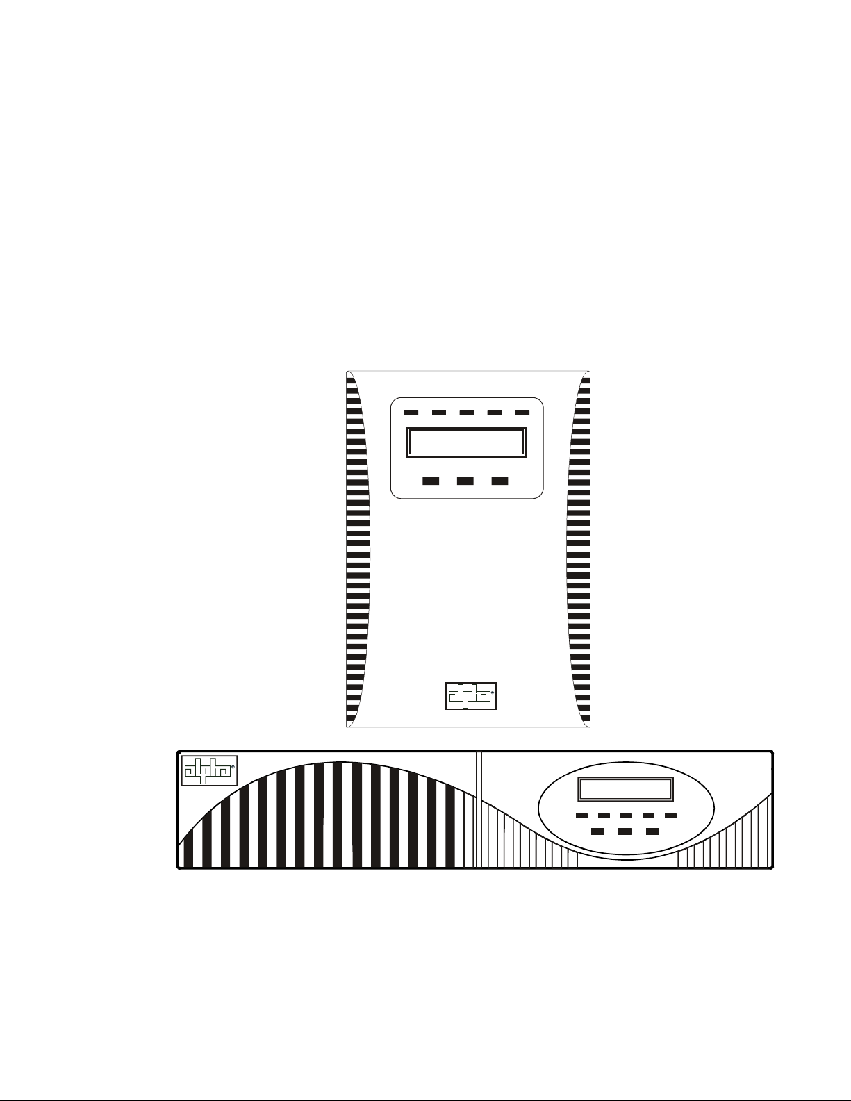
! Pinnacle Plus Series
!!
700/1000/1500/2000/3000
Tower and Rack Mount UPS’s
ON-LINEON ON-BATT BYPASS FAULT
ON/OFFFUNC E NTER
Alpha Technologies
ON-LINEON ON-BATT BYPASS FAULT
ON/OFFFUNC ENTER
Page 3
Pinnacle Plus Series
Save This Manual
It contains important installation and operating instructions.
Keep it in a safe place.
CAUTION
Risk Of Electrical Shock
To reduce the risk of electrical shock and to ensure the safe operation of the Pinnacle Plus
Series of UPS’s, these symbols are used throughout this manual. Where they appear only
qualified personnel should carry out the instructions.
A DANGEROUS VOLTAGE exists in this area. Use extreme caution.
ATTENTION: Important operating instructions. Follow them exactly.
NOTICE:
The Pinnacle Plus Series generates, uses and can radiate radio frequencies if not installed and
tested in accordance with the instructions contained in this manual. It has been tested and found to
comply with the limits established for a Class A computing device pursuant to part 15 of FCC rules
when it is operated alone. It also complies with the radio interference regulations of DOC which are
designed to provide reasonable protection against such interference when this type of equipment is
used in a commercial environment. If there is interference to radio or TV reception, which is determined by switching it on and off, relocate the equipment or use an electrical circuit other than the
one used by the Pinnacle Plus.
i
Page 4
Pinnacle Plus Series
Safety Checklists
DANGER: Do not expose the unit to rain or moisture.
This equipment is to be installed and operated by people trained in the safe use of
high-energy power supplies and their batteries. Also assumed is knowledge of the
local electrical code(s) and how to safely apply them.
DANGER: Sealed lead-acid batteries with high energy and chemical hazards are
used. This manual contains important operation and safety instructions. Only qualified
personnel should service the Pinnacle Plus.
Pinnacle Plus Series Safety Checklist
Carefully unpack the unit. Report any shipping damage at once.
Read this manual. If you have any questions about the safe installation, operation or maintenance of this unit, contact Alpha Technologies’ customer service department.
Before installation, confirm the voltage and current input requirements of the load(s) is
compatible with the unit’s output. Also see the line voltage and current is compatible with
the unit’s input requirements.
Install the unit on a dedicated circuit.
All wiring must meet the local electrical code(s).
Place a warning label on the utility panel to tell emergency personnel an Uninterruptible
Power Supply (UPS) is in the building.
Use proper lifting techniques when moving the unit.
The unit has more than one live circuit. AC power may be present at the outputs even if the
unit is disconnected from line power.
ii
Page 5
Pinnacle Plus Series
Safety Checklists (Continued)
Battery Safety Checklist
There are dangerous voltages inside the unit. Only qualified people should perform installation and maintenance.
Live battery wires must not touch the unit’s chassis or any other metal objects. This can
cause a fire or explosion.
Inspect the batteries once a year for signs of cracks, leaks or swells. Replace as required.
When batteries are in storage, charge them at least once every three months for
optimum performance and to extend their lifetime.
Always replace batteries with ones of identical type and rating. Never install old or un-
tested batteries.
Use insulated tools during servicing.
Remove all rings, watches, jewelry or other conductive items before working inside the
unit.
Follow local regulations for battery disposal. Recycling is the best method.
Never burn batteries to dispose of them. They may explode.
Never open the batteries. The contents are toxic.
Battery Emergency Procedures:
If electrolyte splashes on your skin, immediately wash the skin with water. If electrolyte gets into your eyes, wash them for at least 10 minutes with clean water or a
special neutralizing eye wash solution. Seek medical attention at once.
Neutralize spilled electrolyte with special neutralizing solutions in a “spill kit” or a
solution of 1 lb. of bicarbonate of soda in 1 gallon of water.
iii
Page 6

Table of Contents
1. Introduction ......................................... 1
1.1 The Pinnacle Plus Advantage ................... 2
1.2 Unpacking and Inspection Checklist ......... 3
1.3 The Pinnacle Series ................................. 5
2. Installation ............................................. 9
2.1 Pre–Installation Checklist ....................... 10
2.2 Wiring the Unit ....................................... 10
2.3 Connecting External Battery Packs ....... 11
2.4 Connecting an Emergency Power Off Switch
......................................................... 12
2.5 Connecting the RS–232 Port .................. 13
2.6 Network Connection ............................... 13
3. Operation ............................................ 14
3.1 Turning the Unit On and Off .................... 15
3.2 Using the Control Panel ......................... 16
3.3 Self Test ................................................. 17
3.4 Changing the Parameters ....................... 17
3.5 Troubleshooting ...................................... 20
3.6 Battery Replacement ............................. 21
3.7 Specifications......................................... 22
Pinnacle Plus Series
Warranty ...................................... 23
iv
Page 7

1
Section 1
Introduction
This section introduces you to the
Pinnacle Plus series of UPS’s:
• The Pinnacle Plus series many advantages
(Section 1.1).
• An unpacking and inspection checklist
(Section 1.2).
• An tour of the units, their connectors,
switches and control panels (Section 1.3).
Page 8

1 Introduction
2
1.1 The Pinnacle Plus Series Advantage
The Pinnacle Plus series is an indoor Uninterruptible Power Supply (UPS) that uses advanced
technology to protect computer networks, telecommunications installations and other vital instruments from power line disturbances.
The Pinnacle Plus series uses a double conversion circuit and a digitized microprocessor to
provide continuous power to the loads. It offers complete protection against brownouts, spikes,
sags, voltage transients and frequency changes.
!
Automatic Shutdown/Restart
The Pinnacle Plus series shuts down when the batteries are discharged, preventing damage
to the unit. When line power is requalified, the Pinnacle automatically restarts, providing
power to the loads and recharging the batteries.
!
RS–232 Communication
The Pinnacle Plus series can be remotely monitored and controlled.
! LCD/LED Display Panel
The LCD/LED display provides “at-a-glance” monitoring.
! Battery Charge Display
The LCD shows the battery % charge, battery backup time and battery voltage.
! Load Display
The LCD shows the unit’s % loading and the loading in watts and VA.
! Automatic Bypass
When the Pinnacle Plus detects an internal fault such as deep battery discharge or an overload, it automatically uses its built-in bypass circuit to switch the load to line power.
! Fully Digitized Microprocessor Controlled
Pure sine wave output with less than 3% THD.
! Cold Start
If there is no line at the input, the Pinnacle automatically provides battery power to the load.
! Load Shedding
The power management software allows less important equipment to be turned off during
power outages to save battery power for the critical loads.
Alpha Technologies
Page 9
3 1 Introduction
1.2 Unpacking and Inspection Checklist
TIP: If items are missing or damaged, contact Alpha and the shipping company at
once. Most shippers have a short claim period.
Carefully remove the unit from its shipping container. Inspect it for damage and make sure the
following items are included:
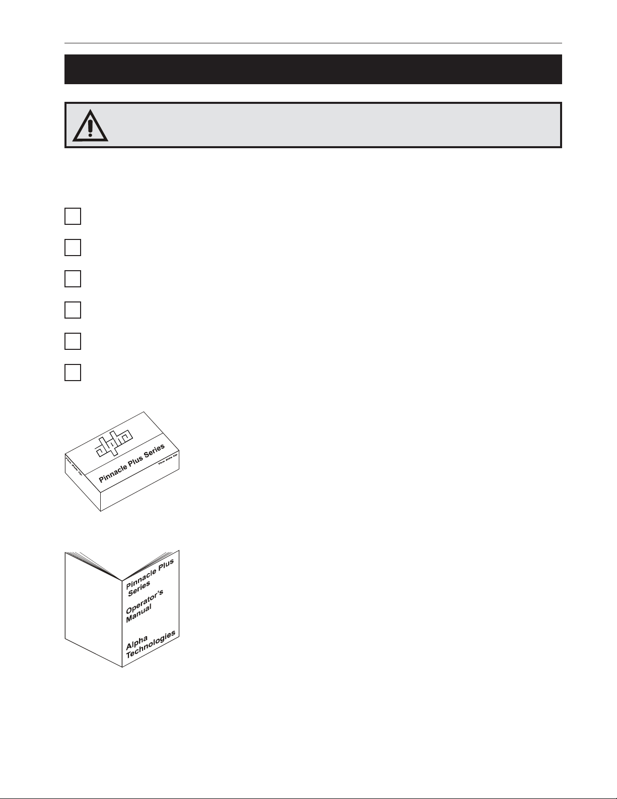
One Pinnacle Plus series UPS with pre-installed batteries.
One operator’s manual.
One power cord.
One Alphamon CD-ROM.
One RS–232C interface cable.
Any ordered options.
Save The Original Shipping Container
If you need to return the unit for servicing, pack it in the original shipping
container. Alpha is not responsible for damage caused by the improper
packaging of returned units.
Read This Manual
Before installation, become familiar with your unit by reviewing the
procedures and drawings in this manual. If you have any questions
about the safe installation, operation or maintenance of the unit, contact
Alpha’s customer service department.
Alpha Technologies
Page 10

1 Introduction
4
1.2 Unpacking and Inspection Checklist (Continued)
For technical support contact Alpha T echnologies customer service department directly at:
:setatSdetinU 0632-746)063(
:adanaC 6741-034)406(
:modgniKdetinU 011105-9721-44+
:ynamreG 0-98897-2219-94+
:tsaEelddiM 57657-352-753+
:ailartsuA 0233-2279-2-16+
For emergency technical support 7 days a week / 24 hours a day call:
USA: 1–800–863–3364
CANADA: 1–800–667–8743
Complete the following for your records
Serial # __________________________________
Options __________________________________
Purchase Date ____________________________
This Pinnacle Plus was purchased from
Dealer ___________________________________
City _____________________________________
State/Province_____________________________
Zip/Postal Code ___________________________
Country __________________________________
T elephone #_______________________________
Fax #____________________________________
E Mail ___________________________________
Alpha T echnologies
Page 11
5 1 Introduction
1.3 The Pinnacle Plus Series
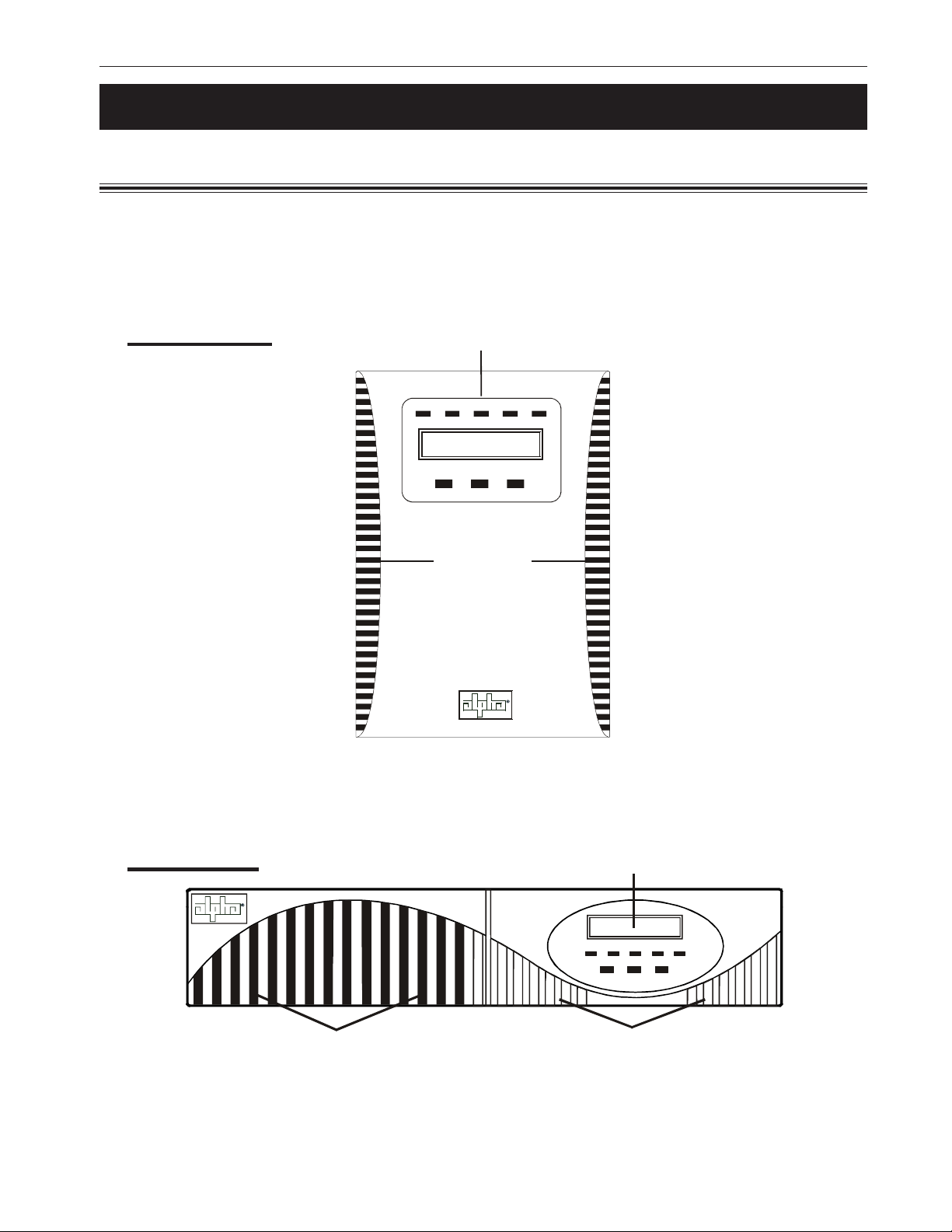
1.3.1 Front Panel
These drawings are used for illustrative purposes only. See your unit for the exact location and
type of all switches and controls. The batteries are reached through this panel.
The control panel’s operation is described in Section 3.2.
Tower Mount
Control Panel
ON-LINEON ON-BATT BYPASS FAULT
ON/OFFFUNC E NTER
Cooling Vents
(Must not be blocked)
Rack Mount
Cooling Vents
(Must not be blocked)
Control Panel
ON-LINEON ON-BATT BYPASS FAULT
FUNC ENTER
Removable Battery Cover
ON/OFF
Alpha Technologies
Page 12
1 Introduction
6
1.3 The Pinnacle Plus Series (Continued)
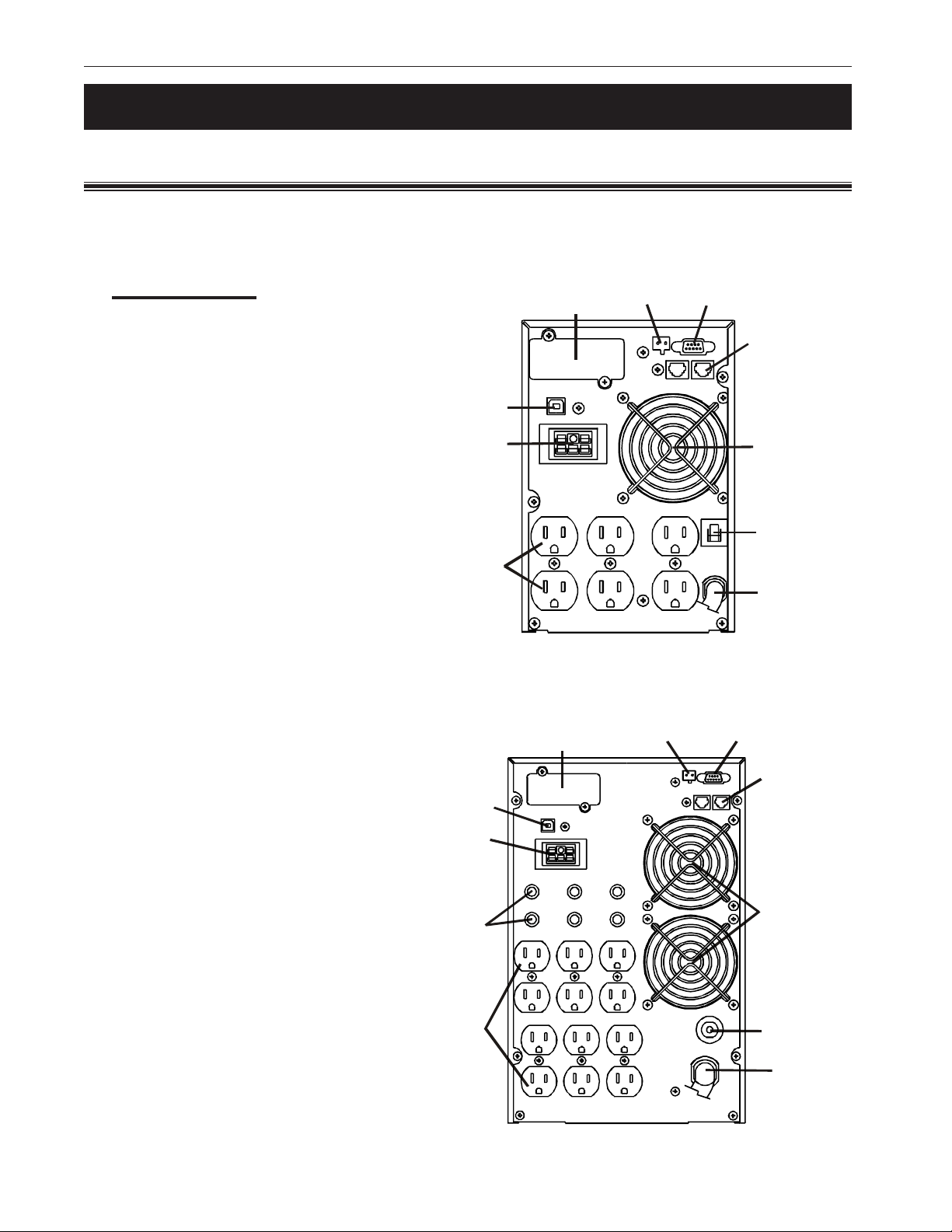
1.3.2 Rear Panel
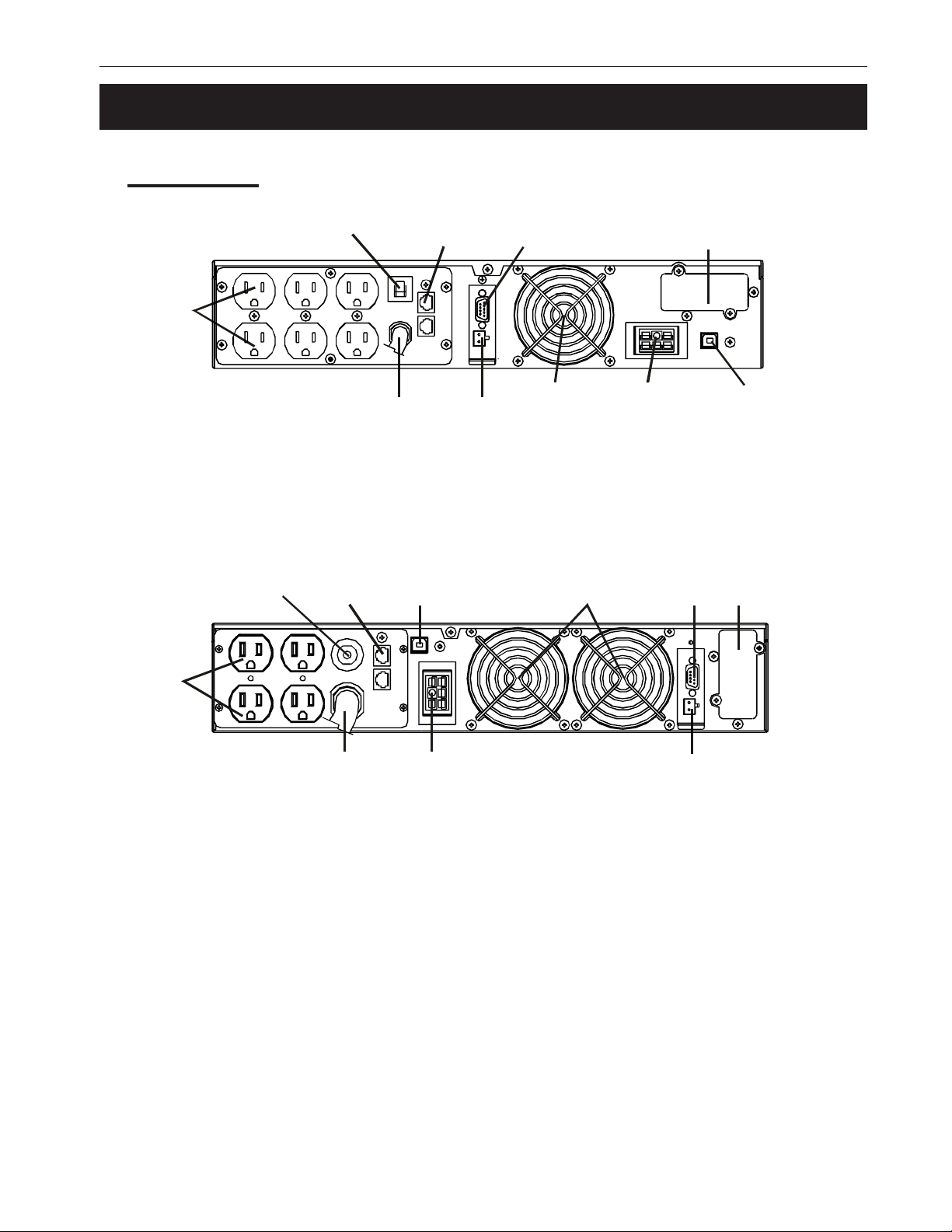
These drawings are used for illustrative purposes only. See your unit for the exact location and
type of all connectors, switches and circuit breakers.
Tower Mount
Figure 1.1
700VA/1KVA/1.5KVA
Optional
USB Port
Optional
External
Battery
Connector
Outlets
Optional
Interface
Optional
Interface
EPO RS-232
EPO
RS-232
Network
Transient
Protector
Cooling
Fan
Input
Circuit
Breaker
Input
Power
Connector
Figure 1.2
2KVA–3KVA
Alpha Technologies
Optional
USB Port
Optional
External
Battery
Connector
Output
Circuit
Breakers
Outlets
Network
Transient
Protector
Cooling
Fans
Input
Circuit
Breaker
Input
Power
Connector
Page 13
7 1 Introduction
1.3 The Pinnacle Plus Series (Continued)
Rack Mount
Outlets
Input Circuit
Input Circuit
Breaker
Breaker
Network
Transient
Protector
Network
Transient
Protector
EPO
RS-232
Cooling
Fan
Figure 1.3
700VA/1K/1.5KVA
Optional USB Port
Optional External
Battery Connector
Cooling
Fans
Optional Interface
Optional
USB PortInput
RS-232
Optional
Interface
Outlets
Input
Optional External Battery Connector
Figure 1.4
2KVA–3KVA
EPO
Alpha Technologies
Page 14
1 Introduction
8
1.3 The Pinnacle Plus Series (Continued)
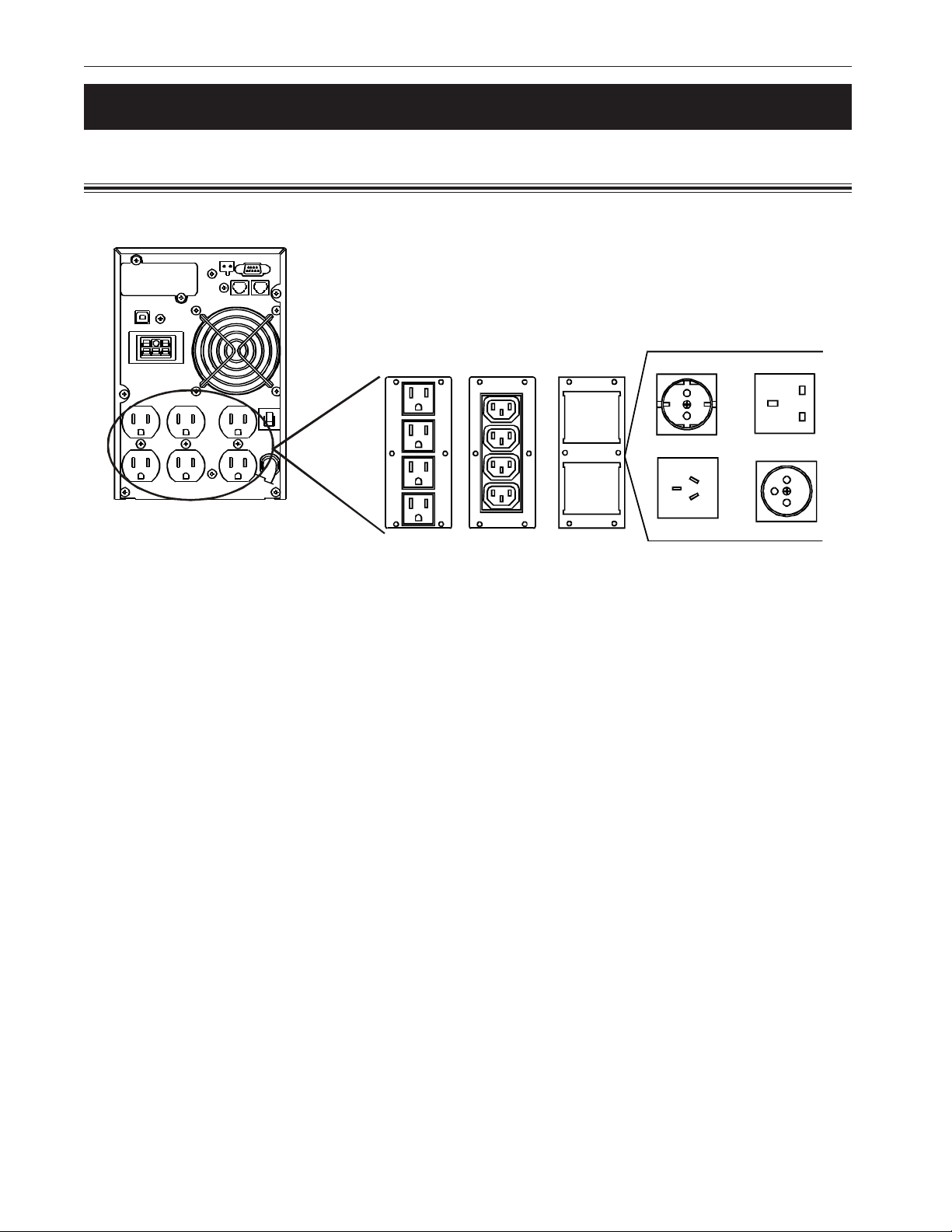
1.3.3 Available Output Connectors
Multiple configurations are available from the factory for various requirements.
AMERICAN IEC
Figure 1.5
Output Connectors
GERMAN BR ITI SH
FRENCH
AUSTRA LI AN
Alpha Technologies
Page 15

9
Section 2
Installation
This section tells you how to install
the Pinnacle Plus series.
• A pre-installation checklist (Section 2.1).
• How to connect the unit to the line and the
loads (Section 2.2).
• How to connect an external battery pack
(Section 2.3).
• How to connect an emergency power off
switch (Section 2.4).
• How to connect the RS–232 port (Section 2.5).
• How to connect the unit to a network
(Section 2.6).
Page 16

2 Installation
10
2.1 Pre-Installation Checklist
Placement
The Pinnacle Plus is an indoor unit. Install it in a dry, dust-free, well-ventilated area with a
temperature of between 60°F to 77°F (15°C to 25°C). Place it on a flat, level surface that
will support its weight (up to 73 lbs, (33 kg)).
The front panel must be easily accessible to the operator.
Do not block the unit’s ventilation slots or the fans. There must be at least 4 inches (100 mm)
between the rear panel and the wall and 2 inches (50 mm) between the walls and the side
panels.
Utility Circuit Breaker
Wire the unit to a dedicated circuit equipped with a circuit breaker. See Section 3.7 for
the unit’s input specifications. All wiring should meet the National Electrical Code ANSI/
NFPA 70.
Grounding
Older facilities may have improper grounding. A qualified electrician should inspect it before
installation to see that it meets the local electrical code.
Adding New Equipment
Shut down the unit (Section 3.1) and then disconnect the line cord before adding any new
loads, battery packs or other equipment.
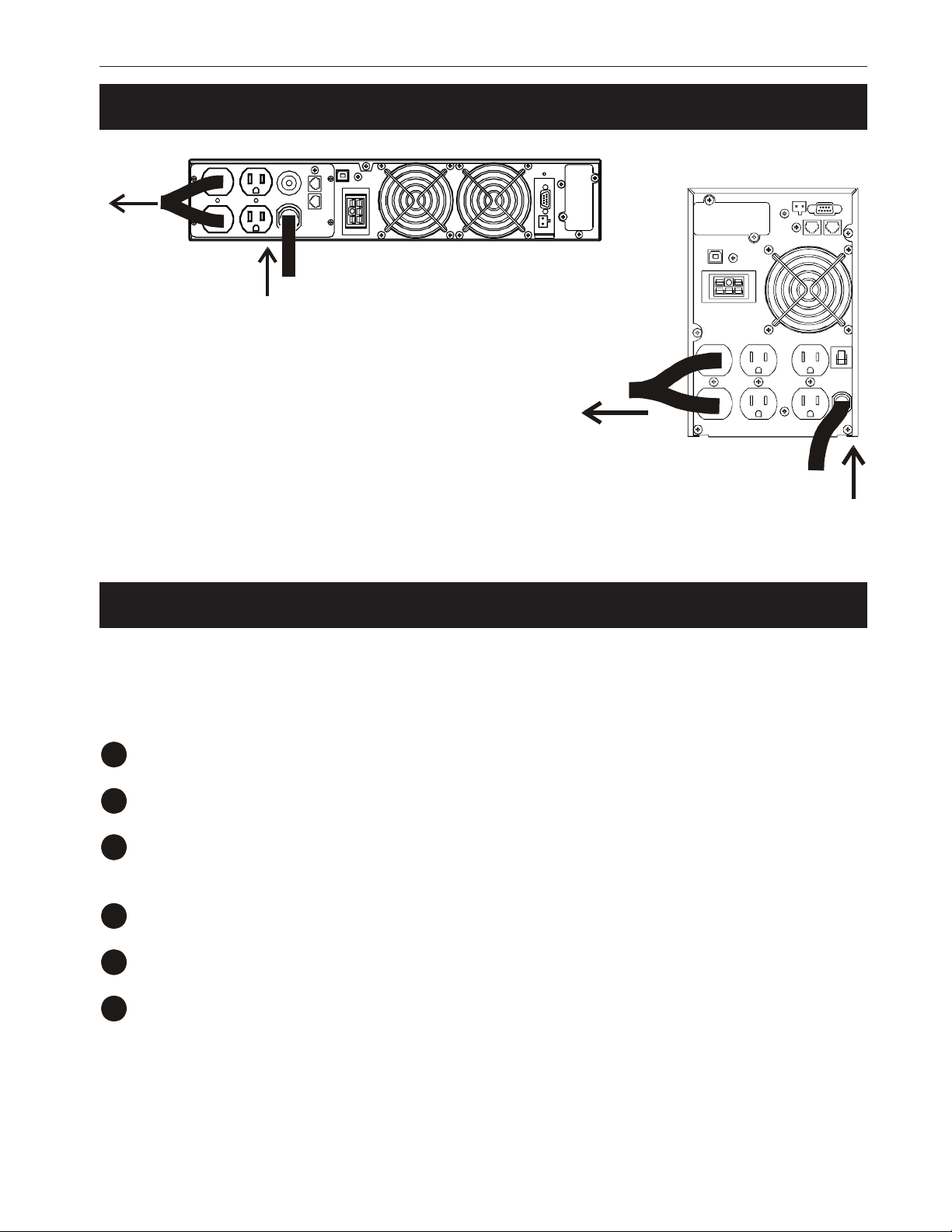
2.2 Wiring the Unit
Procedure:
Connect the load(s) to the unit’s output connector(s) (Figure 2.1).
1
Connect RS–232 or other communications, emergency power off switch, battery packs or
2
any other options (Sections 2.3 to 2.6).
Connect the line to the unit’s input connector.
3
TIP: Determine what output voltage you are using. When starting the unit for the first
time, see if you need to configure the unit’s output voltage (Section 3.4).
Wiring Finished
Turn on the unit as described in Section 3.1.
Alpha Technologies
Page 17
11 2 Installation
2.2 Wiring the Unit (Continued)
To Lo a ds
From Line
To Loads
Figure 2.1
Input/Output Wiring
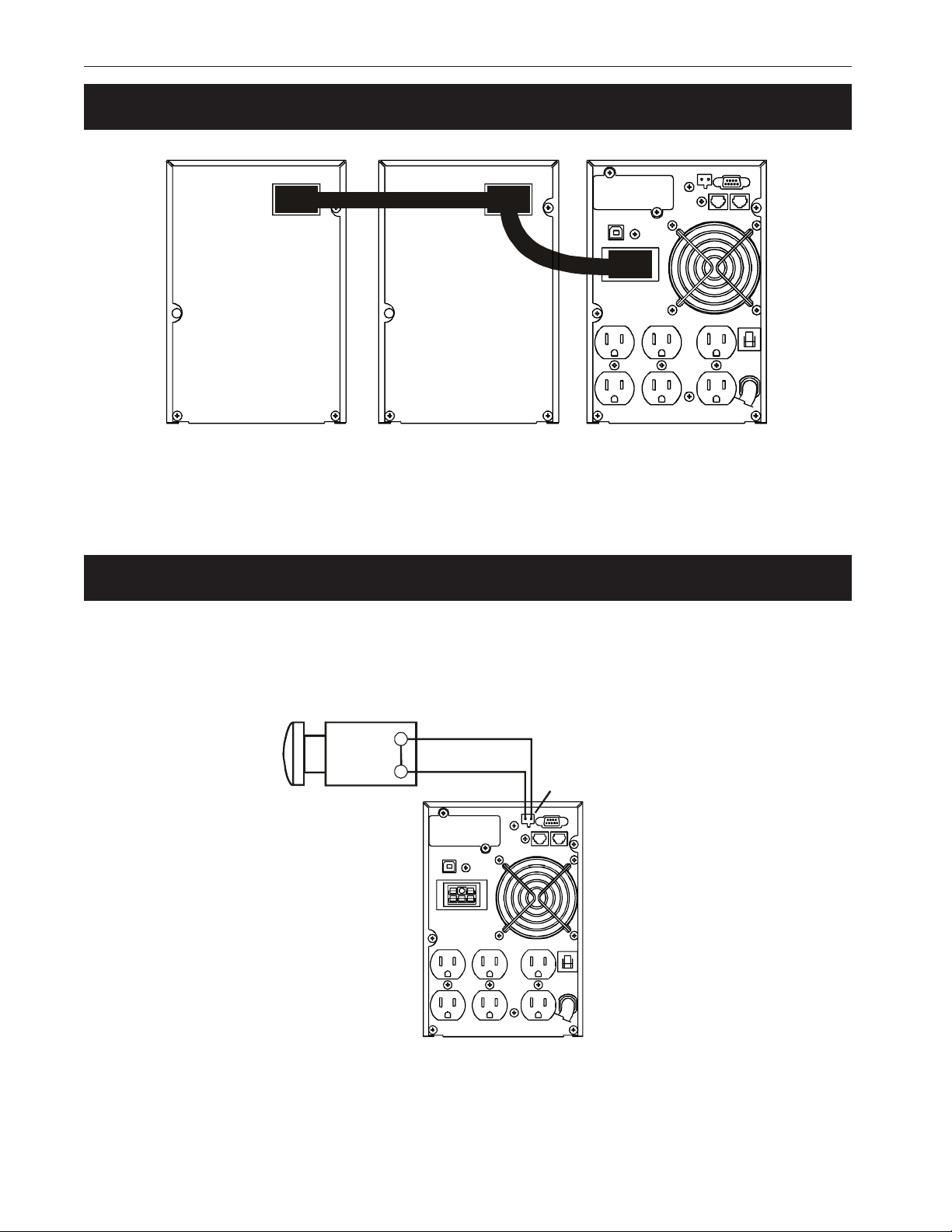
2.3 Connecting External Battery Packs
Up to 2 external battery packs can be connected. Place them next to the unit.
Procedure:
Turn off the unit (Section 3.1).
1
Disconnect the unit from the line and the load(s).
2
Connect the cable from the battery pack to the unit (Figure 2.2). If used, connect the second
3
battery pack to the first pack.
Connect the loads to the unit.
4
Line In
Connect the line to the unit.
5
Turn on the unit (Section 3.1).
6
Battery Pack Connection Finished
Alpha Technologies
Page 18
2 Installation
12
2.3 Connecting an External Battery Pack (Continued)
Figure 2.2
External Battery Pack Connection
2.4 Connecting an Emergency Power Off Switch
An Emergency Power Off (EPO) switch is connected to the rear panel’s EPO connector. When
this switch is opened, the unit shuts off. To restart the unit, turn it on (Section 3.1).
Normally Closed Switch
EPO Connector
Alpha Technologies
Figure 2.3
Emergency Power Off Switch Wiring
Page 19
13 2 Installation
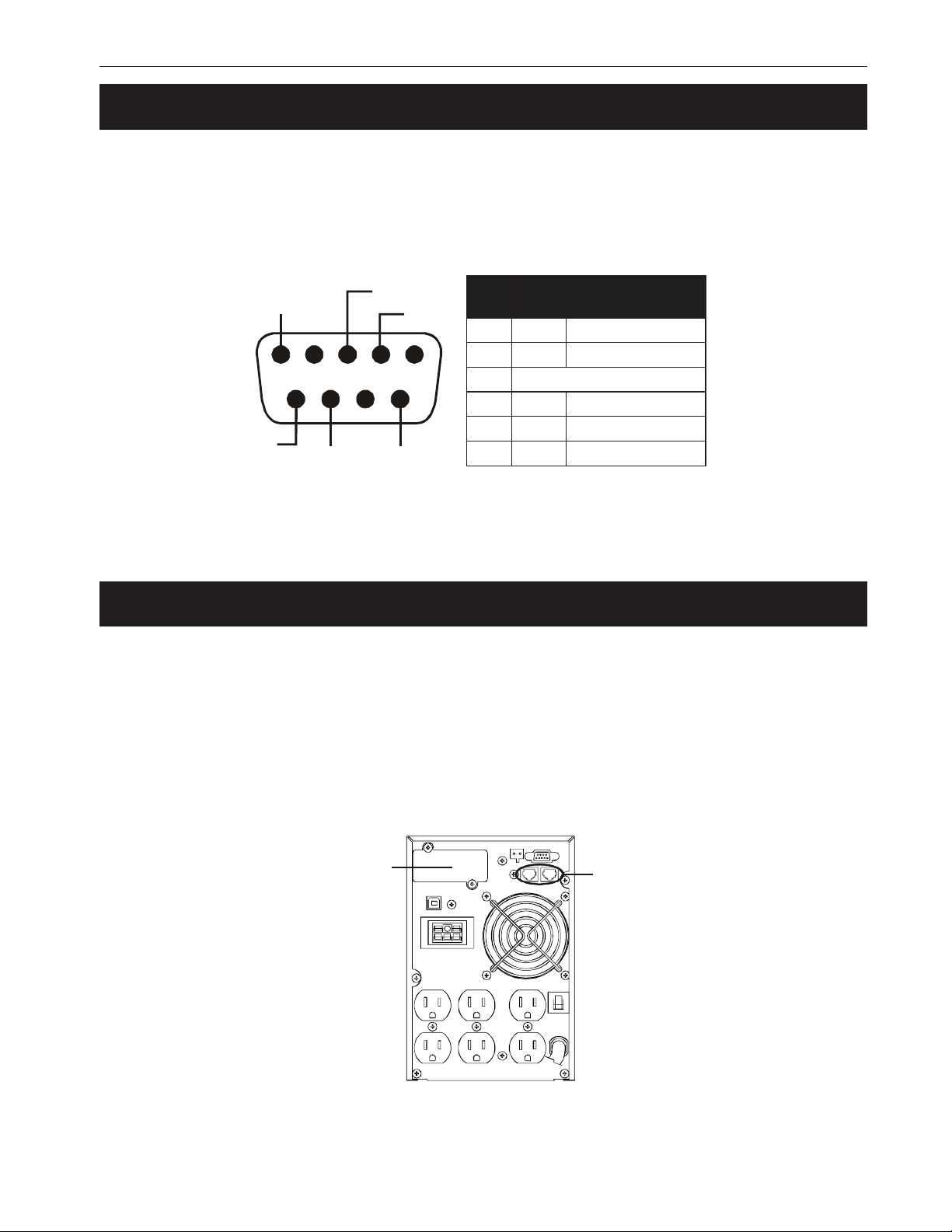
2.5 Connecting the RS-232 Port
With the Alphamon software, you can remotely control the unit with RS-232 communications. It
supports Windows 95/98/ME/2000/NT/XP, Novell NetWare or Linux. The CD that came with the
unit contains installation instructions. Only use the connection cable that came with the unit.
TIP: If the optional USB port is used, the RS-232 port is automatically disabled.
langiS
emaN
noitcnuF
Common
5
RI
RxD
CTSDCD
TxD
1234
6789
#niP
2DxTtuptuODxT
3DxRtupnIffOretrevnI/DxR
5nommoC
6STCtuptuOliaFCA
8DCDtuptuOyrettaBwoL
9IRrewoPCDV42--8+
Figure 2.4
DB–9 Port Pin Out
2.6 Network Connection
The rear panel’s Network Transient Protector allows the unit to be connected to a network. It
uses a single RJ-45 (10BaseT) network card. Plug the input connector to the “IN” connector and
the output connector to the “OUT” connector.
Two communication cards can be installed. The SNMP card allows control and management
over a network or the internet. The AS/400 card allows voltage free relay contacts. Contact
Alpha Technologies for more information and availability.
SNMP or
AS/400 card
Network
Transient
Protector
Figure 2.5
Network Connections
Alpha Technologies
Page 20

14
Section 3
Operation
This section tells you how to operate
the Pinnacle Plus series.
• How to turn the unit on and off (Section 3.1).
• How to use the control panel (Section 3.2).
• How to perform a self test (Section 3.3).
• How to change the unit’s parameters
(Section 3.4).
• How to troubleshoot the unit (Section 3.5).
• How to replace the batteries (Section 3.6).
Page 21
15 3 Operation
ON-LINE
ON-BATT
ON-LINEONON-BATT
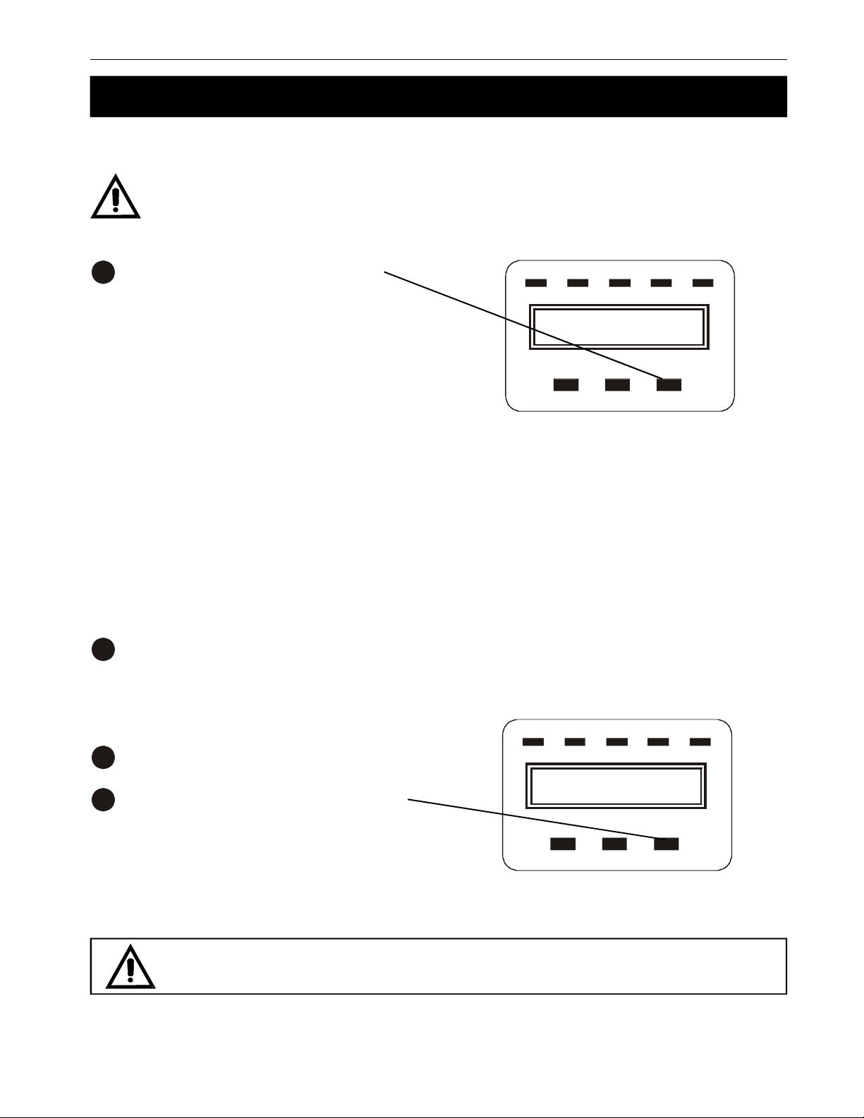
3.1 Turning the Unit On and Off
Turn On:
Before turning the unit on for the first time, determine what output voltage you need. If
needed, change the unit’s output voltage parameter (Section 3.4) before turning on
the load.
Press down the ON/OFF button until
1
“Ready On” appears on the LCD. The fan
turns on.
The LCD shows “Ready On” while it conducts a self test. The ON LED turns on. If
line power is sent to the loads, the ONLINE LED turns on. If battery power is sent
to the loads, the ON-BATT LED turns on.
TIPS:
1) A brand new unit needs to charge the
batteries before the maximum run time is
reached. This takes about 24 hours after
the unit is turned on.
2) If you are changing the unit’s parameters (Section 3.4), change them before
turning on the loads.
Turn on the loads.
2
ON
Line Mode
BYPASS FAULT
ON/OFFFUNC ENTER
Turn Off:
Turn off the loads.
1
Press down the ON/OFF button for five
2
seconds.
The LCD shows “Shutdown” then “UPS Off”
then becomes dark. The fan and the ON LED
turns off.
For emergency shutdowns, install an Emergency Power Off switch (Section 2.4).
BYPASS FAULT
UPS Off
ON/OFFFUNC ENTER
Alpha Technologies
Page 22
3 Operation
ON-LINE
ON-BATT
ON/OFF
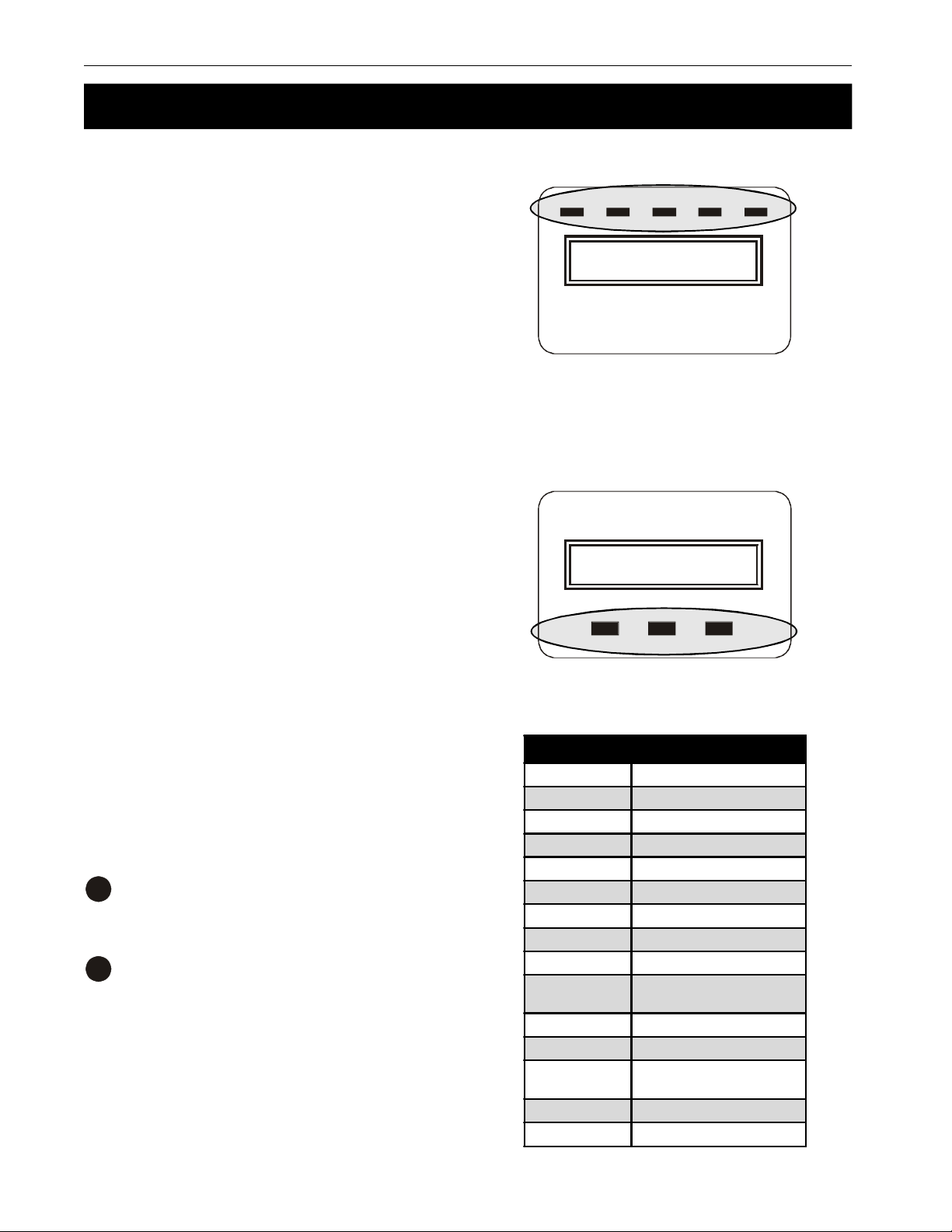
3.2 Using the Control Panel
LEDs:
• ON: The unit is on.
• ON-LINE: Line power is provided to the
loads.
• ON-BATT: Backup battery power is
provided to the loads.
• BYPASS: Line power is provided to the
loads via the unit’s bypass circuit.
• FAULT: The unit has a fault. Do trouble-
shooting (Section 3.5). Press any push
button to turn off the alarm.
Push Buttons:
• ON/OFF: This turns the unit on and off.
16
ON
Line Mode
BYPASS FAULT
• ENTER: This sets the parameter you
have selected.
• FUNC: This scrolls through the menus.
If no action is taken in 10 seconds, the LCD
returns to its original status.
Meter Display:
Measurements are made with the display
panel. These read only items are listed in the
table to the right.
To make a measurement:
Press FUNC for 5 seconds.
1
“O/P Volt” appears.
Press FUNC to move down the list.
2
If no action is taken in 10 seconds, the LCD
returns to its original status.
Line Mode
FUNC ENTER
LCD Shows Description
O/P VOLT The AC voltage output
O/P FREQ The output frequency
I/P VOLT The input AC voltage
I/P FREQ The input frequency
BAT VOLT The battery voltage
O/P LOAD The % loading
O/P Watt The output in watts
O/P VA The output in VA
O/P CURR The output current
BACKUP TIME
BAT CHARG The % battery charge
TEMPERATURE The ambient temperature
BAT PACK NUM
RATING The UPS's power rating
CPU VERSION The CPU used in this unit
Estimated backup time in
minutes
The number of external
battery packs
Alpha Technologies
Page 23

17 3 Operation
3.3 Self Test
The battery test finds out if the batteries can provide backup power. It is started from the Parameters menu (Figure 3.1). This should not be done for the first 24 hours after a new unit is installed so the batteries can be fully charged. Every 30 days, the unit automatically does a battery
discharge test. If it finds a problem, it is displayed on the LCD.
Procedure
TIP: If no buttons are pushed for 10 seconds, the LCD exits this menu and displays the operat-
ing mode.
Press the FUNC button for 5 seconds.
1
The first parameter, “O/P Volt Set” is displayed on the LCD (Figure 3.1).
Press FUNC to scroll through the parameters until “Battery Test” appears.
2
Press the ENTER button. When the LCD shows “Test?” press ENTER.
3
The test starts and the LCD shows “Battery Test.”
After the test, the unit resumes line mode and the LCD shows “Line Mode.” If a fault is found,
4
the FAULT LED is on. Do troubleshooting as described in Section 3.5.
Self Test Finished
3.4 Changing the Parameters
You can change the unit’s factory set parameters to suit your local conditions (Figure 3.1). Any
changes should be done after the unit is started, but before the loads are turned on.
Procedure
TIP: If no buttons are pushed for 10 seconds, the LCD exits this menu and displays the operat-
ing mode.
Press the FUNC button for 5 seconds.
1
The first parameter, “O/P Volt Set” is displayed on the LCD.
Press FUNC to scroll through the parameters (Figure 3.1).
2
Press ENTER to select a parameter..
3
Alpha Technologies
Page 24

3 Operation
18
3.4 Setting the Parameters (Continued)
Press FUNC to display the selections. Press ENTER to select the selection.
4
If the LCD shows “Save?” press ENTER to set the unit to the new parameter.
Parameter Changing Finished
Parameter LCD Shows Description Available Selections Factory Default
Output Voltage O/P Volt Set
Input Frequency I/P Freq Set
Input/Bypass
Voltage
Free Run Mode
(See Note 4)
Bypass
Enable/Disable
at Free Run
mode
(See Note 4)
HE Mode Setting
(See Note 1)
Force Manual
Bypass
Management of
Load Groups
Battery Test Battery Test Tests if the battery can provide backup power
I/P Bypass Set
Free Run Set
Bypass Disable
HE Mode Set
Manual Bypass FOR SERVICING ONLY *
Outlet Setting
Select the nominal
output voltage
Select the input frequency
range when UPS goes into free
run mode
Select the input voltage range
when bypass is available
Select if the UPS can operate
in free run mode
(unsynchronized)
If enable is selected, the UPS
can go to bypass when
unsynchronized
Select if the UPS can run in
high efficiency mode
You can turn the two load
groups on and off from the front
panel
208/220/230/240 VAC 230 VAC
100/110/115/120/127 VAC 120 VAC
±2%, ±5%, ±7% ±5%
±10%, +10/-15%, +15/-20% +10/-15%
ON/OFF ON
Disable/Enable Disable
ON/OFF OFF
1 ON & 2 ON
1 OFF & 2 ON
1 OFF & 2 OFF
1 ON & 2 OFF
1 ON & 2 ON
Silence Function Silence Set Turn the audible alarm on or off ON/OFF OFF
Number of
External Battery
Packs
Site Wiring
Alarm
(See Note 3)
Select Language Language Select the UPS's language
Set Generator
Mode
(See Note 2)
Set RS-232
Communication
* For the unit’s and the power management software to operate properly, the manual bypass should be set to OFF. This feature is
meant to be used with an external maintenance bypass switch.
** Turn the unit off and restart after changing this parameter.
Batt Cabinet Set
Sit Fault Set
Generator Set UPS in generator mode** ON/OFF OFF
RS232 Control
This lets the UPS predict the
battery backup time
This enables or disables the
site wiring alarm
Set the UPS's RS-232
communication
0 (if no cabinets are used)
1 (one cabinet used)
2 (two cabinets are used)
Disable/Enable Disable
English, German, French,
Spanish, Italian
Disable/Enable Enable
0
English
Figure 3.1
Parameters
Alpha Technologies
Page 25

19 3 Operation
3.4 Setting the Parameters (Continued)
Notes:
1) HE Mode Set: This is used to set if the unit sends the line power through double conversion
and then to the loads (HE Mode:OFF) or straight through to the loads (HE Mode:ON).
2) Set Generator Mode: This widens the input parameters so the unit can be used with a
generator.
3) Site Wiring Alarm: This tells you if the line’s ground and neutral wiring is reversed.
4) Free Run Mode, Bypass Enable/Disable at Free Run Mode: These two parameters work
together to control the unit’s input voltage or frequency windows.
The available combinations are:
Combination Result
Free Run: ON
Bypass: DISABLED
(Factory Default)
Free Run: ON
Bypass: ENABLED
Free Run: OFF
(Bypass is automatically
turned off)
Free Run/Bypass Combination Table
Input window is:
45-65 Hz (Automatic frequency sensing)
96-138 VAC (60 Hz)
184-265 VAC (50 Hz)
Input voltage window is:
±10%, +10%/-15% or +15/-20% VAC
(operator set)
Input frequency window is:
±2%, ±5% or ±7% Hz
(operator set)
Figure 3.2
Alpha Technologies
Page 26

3 Operation
20
3.5 Troubleshooting
When the fault LED turns on or the audibile alarm is heard, perform troubleshooting as shown in
the table below.
LCD Shows
Output Overload
Battery Test No beeps
Over-Charge
Low Battery
On-Battery
Charger Failure
Over-Temperature
Audible
Alarm *
2 beeps per
second
Constant
beeping
2 beeps
every 5
seconds
1 beep
every 5
seconds
Constant
beeping
Constant
beeping
Description Action
The UPS is overloaded. It is
operating in Bypass mode.
The UPS is performing a
battery test.
The batteries are
overcharged.
The UPS is operating on
battery power and the
batteries are almost
discharged.
The UPS is operating on
battery power.
The charger is faulty. Contact Alpha Technologies.
The UPS is over heating.
Shut down loads, starting with the least
important.
None. The UPS will return to normal
operation when the test is done.
Turn off the loads and the UPS. Contact
Alpha Technologies.
The UPS will automatically restart when the
line becomes requalified.
Shutdown the loads.
--Make sure the UPS's fans and vents are
not blocked.
--Make sure the ambient air temperature is
below 40°C.
--If this does not solve the problem, contact
Alpha Technologies.
Output Short
High Output Voltage
Low Output Voltage
Bus Fault
Site Wiring Fault
Line Abnormal
*To turn off the alarm, press any button on the control panel
Constant
beeping
Constant
beeping
Constant
beeping
2 beeps per
second
1 beep per
second
1 beep per
second
The output is short circuited. Contact Alpha Technologies.
The output voltage is high. Contact Alpha Technologies.
The output voltage is low. Contact Alpha Technologies.
The internal DC bus voltage
There is voltage between the
line's neutral and ground.
Troubleshooting Table
Alpha Technologies
is high.
Figure 3.3
Turn off the loads and the UPS. Contact
Alpha Technologies.
Turn off the loads and the UPS. Correct the
site wiring, then restart the UPS.
Page 27
21 3 Operation
3.6 Battery Replacement
The batteries are replaced without shutting off the unit or the loads. Replace them with the same
quantity and type as the originals.
DANGER: Make sure you have read the safety instructions in the front of this manual.
Only qualified personnel should change them.
Procedure
WARNING: Do not replace the batteries when the ON-BATT LED is on.
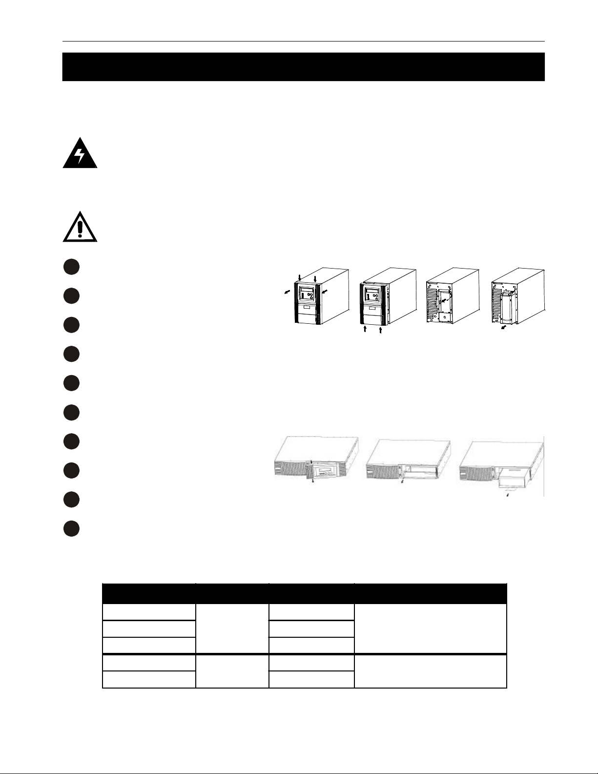
Enable the manual bypass (Section 3.4).
1
Pop off and remove the front cover..
2
Unscrew and remove the battery cover..
3
Remove the battery cartridge from the unit. Take note of the battery configuration and wiring.
4
Replace the batteries with any of the qualified batteries listed in Figure 3.4.
5
Push the cartridge with the new batteries back into the unit.
6
Reinstall the battery cover..
7
Reinstall the front cover..
8
Disable the manual bypass (Section 3.4)
9
Do a self test (Section 3.3).
10
Battery Replacement Finished
Model Battery Type # of Batteries Manufacturer
Pinnacle Plus 700
Pinnacle Plus 1000 3
Pinnacle Plus 2000 6
Pinnacle Plus 1500
Pinnacle Plus 3000 6
12V, 7.2 AH
12V, 9.0 AH
Figure 3.4
Qualified Replacement Batteries
2
3
CSB-GP1272
Panasonic LC-R127R2P
Hitachi HV7-12F2
CSB HR1234W F2
Alpha Technologies
Page 28

3 Operation
3.7 Specifications
700/700RM 1000/1000RM 1500/1500RM 2000/2000RM 3000/3000RM
Electrical
Output VA (W)
Input/Output Voltage (VAC)
Input Current (Max); Amps,
120 VAC Units
Input Frequency (Hz)
Output Frequency (Hz)
Transfer Time (mSec)
Crest Factor
Harmonic Distortion
Output Waveform
UPS Design Technology
High Efficiency Mode
(AC to DC)
Overload Recovery
Surge Protection
Overload Protection
Short Circuit Protection
Battery Type
Battery Protection
Battery Recharge Time
Communication
22
700 (490) 1000 (700) 1500 (1050) 2000 (1400) 3000 (2100)
100 / 110 / 115 / 120 / 127
10 12 15 20 30
50 / 60 (Auto Sensing)
50 / 60 ± 0.5%
0
3:1
< 3% of THD at linear load
Sine
On-Line, fully digitized microprocessor controlled
>95%
Auto transfer to UPS
120V: IEEE C 62.41 / 230V: IEEE 61000-4-5 Level 3
125% for 1 minute and 150% for 10 seconds
UPS output automatically cut off or input fuse/circuit breaker protection
Sealed, maintenance free lead acid
Cut off when battery is low to prevent drainage
4 hours to 90% of capacity
RS-232 serial port / USB port / built-in SNMP slot
Mechanical
Tower Dimensions
W x D x H; in (mm)
Tower Weight; lb (kg)
Rack Mount Dimensions
W x D x H; in (mm)
Rack Mount Weight; lb (kg)
Input Connectors
Environmental
Operating Temperature °F(°C)
Storage Temperature °F(°C)
Altitude (Max); ft (m)
Audible Noise @1 m
Humidity
Conformance
Safety (Designed to Meet)
EMC (EMS / EMI)
Alpha Technologies
6.0 x 16.5 x 9.4 (152 x 420 x 238) 8.9 x 16.7 x 14.2 (225 x 425 x 360)
29.7 (13.5) 35.6 (16.2) 37.4 (17.0) 68.4 (31.1) 72.6 (33.0)
16.9 x 16.7 x 3.3 (428 x 425 x 84) (2RU)
32.1 (14.6) 37.6 (17.1) 39.8 (18.1) 69.5 (31.6) 71.5 (32.5)
NEMA 5-15P NEMA L5-20P NEMA L5-30P
32-104 (0-40)
-4-122 (-20-50)
15000 (3500)
< 40 dBA
up to 95%, non-condensing
UL 1778 / CSA
IEC 61000-4 / FCC Part 15 Class B / CISPR 22
16.9 x 25.0 x 3.3 (428 x 635 x 84)
(2RU)
Page 29

23 Warranty
LIMITED 36-MONTH WARRANTY
AC PRODUCTS
Alpha Technologies warrants its equipment to be free of manufacturing defects in material and workmanship
for a period of 36 months from the date of manufacture. The liability of Alpha Technologies under this warranty
is solely limited to repairing, replacing, or issuing credit for such equipment (at the discretion of Alpha
Technologies), provided that:
1.Alpha Technologies’ Customer Service Department is promptly notified, by facsimile or telephone, that
a failure or defect has occurred.
2.Alpha Technologies’ Customer Service Department issues a Return Materials Authorization (RMA)
number, and designates the service location. The RMA must be clearly marked on the outside of the
shipping container.
3.Purchaser is responsible for all in-bound shipping and handling charges (COD and freight collect will
not be accepted without prior approval from Alpha Technologies); Alpha Technologies will pay out-bound
surface shipping charges for return of repaired equipment.
4.A satisfactory examination of the returned unit by Alpha Technologies’ Service personnel shall disclose
that defects have not been caused by misuse, neglect, improper installation, repair, alteration, or accident,
or failure to follow instructions furnished by Alpha Technologies. If Alpha Technologies’ Service personnel
determine that the unit has been damaged due to one of these causes, or if the unit is free of defects, a
handling or repair fee may be assessed prior to returning the unit.
WITH RESPECT TO BATTERIES, PERIPHERAL DEVICES, ATTACHMENTS OR APPARATUS NOT
MANUFACTURED BY ALPHA TECHNOLOGIES, ALPHA WILL ASSIGN TO THE PURCHASER ITS RIGHTS
UNDER THE ORIGINAL MANUFACTURER’S WARRANTY OF SUCH BATTERIES, PERIPHERAL DEVICES,
ATTACHMENTS OR APPARATUS, BUT OFFERS NO ADDITIONAL WARRANTIES IN CONNECTION
THEREWITH.
THIS LIMITED 36-MONTH WARRANTY IS IN LIEU OF ALL OTHER WARRANTIES, EXPRESS OR IMPLIED,
INCLUDING, BUT NOT LIMITED TO, IMPLIED WARRANTIES OF MERCHANTABILITY AND FITNESS FOR
A PARTICULAR PURPOSE.
IN NO CASE SHALL ALPHA TECHNOLOGIES BE LIABLE FOR ANY INCIDENTAL, SPECIAL OR
CONSEQUENTIAL DAMAGES WHATSOEVER, INCLUDING WITHOUT LIMITATION ANY CLAIM FOR LOST
PROFITS OR REVENUES, EVEN IF ALPHA TECHNOLOGIES HAS BEEN ADVISED OF THE POSSIBILITY
OF SUCH, FOR BREACH OF THIS OR ANY OTHER WARRANTY, EXPRESS OR IMPLIED.
Any action for breach of this limited 36-month warranty must be brought within a period of 36 months from
date of manufacture.
This limited 36-month warranty does not extend to any unit that has been repaired or altered by any party
other than Alpha Technologies or its Authorized Service Center.
Alpha Technologies reserves the right to discontinue particular models and to make modifications in
design and/or function at any time, without notice and without incurring obligations to modify previously
purchased units.
9/04
Alpha Technologies
Page 30

Alpha Technologies
3767 Alpha Way
Bellingham, WA, USA 98226
Tel: (360) 647–2360
Fax: (360) 671–4936
Alpha Technologies Ltd.
4084 McConnell Court
Burnaby, BC, Canada V5A 3N7
Tel: (604) 430–1476
Fax: (604) 430–8908
Alpha Technologies Europe Ltd
Twyford House
Thorley, Bishop's Stortford
Hertfordshire CM22 7PA, UK
Tel: +44–1279–501110
Fax: +44–1279–659870
Alpha Technologies GmbH
Hansastrasse 8
D-91126 Schwabach, Germany
Tel: +49–9122–79889–0
Fax: +49–9122–79889–21
MTI Technologies
P.O. Box 56468
Limassol, Cyprus 3307
Tel: +357–253–75675
Fax: +357–253–59595
Alpha Technologies
Units R5–R7, Regents Park Estate
Cnr Park Rd. and Prince’s Rd East
Regents Park, NSW 2143, Australia
Tel: +61–2–9722–3320
Fax: +61–2–9722–3321
Alpha sales and service offices located throughout the world
© 2004 Alpha Technologies Ltd. http://www.alpha.com
Printed In Canada 017–751–B0 10/04
 Loading...