

Alpha Comm Enterprises AMPLIFIER 9500 User Manual

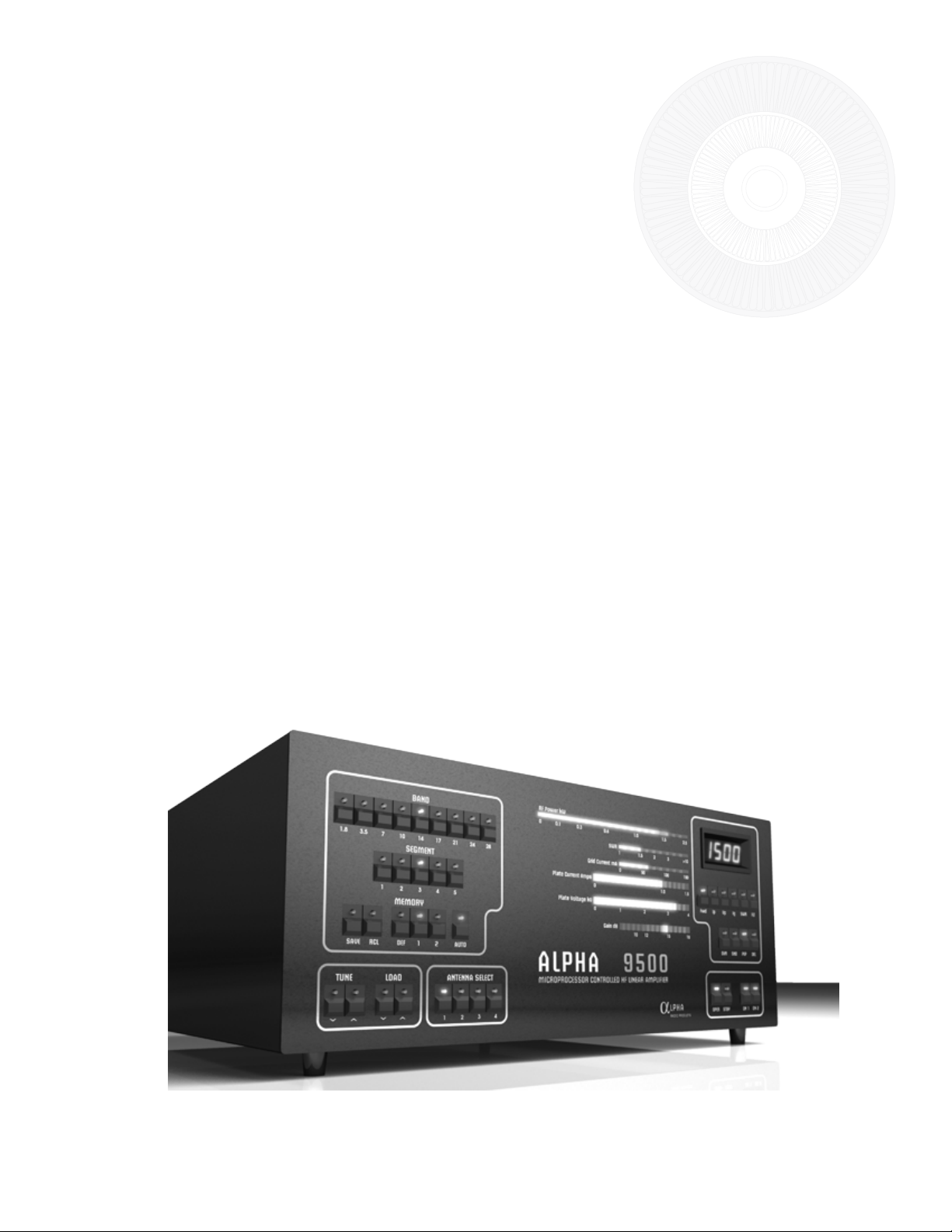
ALPHA 9500
HF LINEAR AMPLIFIER
1
Interim
OPERATING MANUAL
© 2007 Alpha Radio Products, Inc
All rights reserved
Specifications subject to change without notice
ALPHA 9500 Interim OPERATING MANUAL
www.alpharadioproducts.com

2
ALPHA 9500 Interim OPERATING MANUAL
www.alpharadioproducts.com

Table of Contents
3
ALPHA 9500 Interim OPERATING MANUAL
www.alpharadioproducts.com

4
ALPHA 9500 Interim OPERATING MANUAL
www.alpharadioproducts.com

5
ALPHA 9500 Interim OPERATING MANUAL
www.alpharadioproducts.com

6
ALPHA 9500 Interim OPERATING MANUAL
www.alpharadioproducts.com
7
1 Introduction
1.1 General Description
Congratulations on your purchase of a professional quality Alpha 9500 amplifier! With proper
installation and care, you can expect to enjoy your Amateur Radio hobby with this amplifier
improving your signal for many years to come. Please study this manual carefully before
operating your amplifier for the first time.
The Alpha 9500 is a self-contained manual tune HF linear power amplifier capable of continuous
operation at 1500 W peak power output on SSB, keyed CW, SSTV, RTTY, digital modes or FM, with
no time limit.
Other Alpha products available to enhance your use and enjoyment of the 9500 amplifier include:
• Alpha 2100 full 1500-watt rated 50-ohm dummy loads and
• Alpha 4500 series SWR meters / Wattmeters
See our web site at www.alpharadioproducts.com or call 303-473-9232 for further information.
ALPHA 9500 Interim OPERATING MANUAL
www.alpharadioproducts.com

8
1.2 Amplifier Capabilities
CAUTION:
It is extremely important to thoroughly review the Installation and Operation
sections of this manual before attempting to use the Alpha 9500. Failure to do so
could result in serious damage not covered under warranty.
• Continuous RF Output. The 9500 is capable of 1.5 kW continuous RF output on all commonly
used modes and on any authorized amateur frequency from 1.8 to 29.7 MHz.
• Compatibility with popular amateur transceivers and exciters. The 9500 requires approximately
50-65 W peak RF drive for 1.5 kW output.
• Capable of full CW break-in, QSK and all digital modes when used with any appropriate
transceiver.
• Protective functions are built in. The control system incorporates protective functions that
minimize the probability of accidental damage to the amplifier or its power tubes. In most cases,
when one of the protective functions is “tripped,” the amplifier will go to Standby.
• USB and Serial interface allow for remote operations, diagnostic and firmware upgrades.
1.3 Shipping Information
The Alpha 9500 amplifier ships in two heavy-duty cardboard cartons. One carton holds the power
transformer and weighs 43 lb (20 kg) and the second carton contains the amplifier and weighs 39 lb. (18
kg). Both of these cartons are mounted on a wooden pallet and strapped down for secure shipping.
Alpha recommends that you retain the pallet and the cartons after installation in the unlikely
event that you need to ship the unit later. Contact Alpha at 303.473.9232 for shipping advice and
assistance.
1.4 Safety Information – Installation and Operation
• Make sure the Alpha 9500 is located where there is good air circulation all around and on
top of the cabinet. The unit may become hot during operation.
• The Alpha 9500 weighs approximately 69 pounds when the transformer is installed. Use
ALPHA 9500 Interim OPERATING MANUAL
www.alpharadioproducts.com

9
proper lifting techniques and two people when moving the amplifier.
• The Alpha 9500 is designed to meet international safety standards and FCC regulations.
However, one should always remember that the equipment works with high voltages that
can be LETHAL!
This operating manual holds information, cautions and warnings that must be followed to ensure
safe installation and operation. Read Chapter 1 before attempting to unpack or operate the
Alpha 9500 amplifier.
Warnings: What Not to Do
• Never open the amplifier case without unplugging the unit from the wall outlet.
• Never stick objects into holes in the case.
• Never touch an antenna during transmission.
• Never attempt to turn on the amplifier without the cover securely in place (all
attachment screws reinserted).
• Never turn the amplifier back on after a hard fault without waiting at least 20
seconds.
• Always resist the temptation to immediately hit the ON button after the
amplifier faults to power off.
• Never allow liquids to enter the amplifier through the cover holes.
• Never cover or obscure the exhaust holes in the cover of the amp.
Warnings posted in this manual should be read and thoroughly understood
by users. Failure to perform procedures properly may result in amplifier
damage, fire hazard, or electric shock.
1.5 Owner Assistance
Technical Assistance from Alpha Radio Products is available from several sources.
• The Alpha Radio Products web site is www.alpharadioproducts.com. Click on Support and
follow the instructions. Many typical problems and their solutions are listed on this site. On
this site you can get the following assistance:
• Technical Support
• Repair Information
• Software Downloads
• Manuals
ALPHA 9500 Interim OPERATING MANUAL
www.alpharadioproducts.com

10
• Tech Tips
• Legacy Equipment Information
• FAQs
• You can e-mail us for customer support at service@alpharadioproducts.com or you can send
your request by fax to 303.473.9660.
• Our phone number is 303.473.9232
ALPHA 9500 Interim OPERATING MANUAL
www.alpharadioproducts.com

11
2 Quick Start Information
2.1 Overview
This section explains in brief the items you need to consider when setting up your Alpha 9500
amplifier.
If you already have a well-designed shack and have used an amplifier before, please review the
items below to make sure you have considered all the critical items for proper installation and
operation.
If you are using an amplifier for the first time, please skip this section and go to sections 3, 4, and
5 for a more detailed explanation of how to set up your shack for maximum safety and operating
enjoyment.
If you have installation questions, do not hesitate to contact Customer Support. We much prefer
to address questions prior to power up.
2.2 Station Engineering Considerations - Checklist
Make sure you have properly addressed the following concerns (Section 2.3 below) before
installation of your Alpha 9500 amplifier. If you are unsure of any of these items, please read the
noted sections carefully.
2.3 Preparation
__ 220V AC Power in shack? (Section 3.2)
__ Amplifier placed with proper airflow? (Section 3.3)
__ Antenna ready for 1,500W? (Section 3.4)
__ Adequate RF cabling? (Section 3.5)
ALPHA 9500 Interim OPERATING MANUAL
www.alpharadioproducts.com

12
2.4 Unpacking
__ Unit Checked for Damage?
__ Blower screw removed?
__ Transformer Installed? (Section 4.2.1, 4.2.2)
__ Power Cord Connector Attached? (Section 4.2.3)
__ Amplifier Grounded Properly? (Section 4.4.1)
__ Amplifier Cover Replaced and Secured? (Section 4.4.2)
2.5 Operation
__ All Exciter Interconnections Set? (Section 6.2)
__ Exciter Drive Correctly Set? (Section 6.1.1)
__ Amplifier Tuned to Antenna System? (Section 6.3.6)
ALPHA 9500 Interim OPERATING MANUAL
www.alpharadioproducts.com

13
3 Station Engineering Considerations
3.1 Overview
The Alpha 9500 is capable of dramatically improving the performance of your amateur station.
It is important that you observe good engineering practices to achieve all the benefits of such a
station in a safe and reliable manner. This section provides a few hints for important operational
considerations, but it is recommended that the user also consult a good source of general
information such as “The Radio Amateur’s Handbook” by the ARRL, especially if this is the first
high-power amplifier you have used.
3.2 AC Power Source
This amplifier runs best when powered by a 200V - 240V AC circuit. If you do not have a 220V
AC outlet in your shack, you will need to get a licensed electrical contractor to install one. A
minimum of a 20 amp capacity is required. A 20 amp breaker on your 220V circuit is sufficient.
There are many styles of plugs, some of which are country-specific. For this reason, the amplifier
is not shipped with a power plug. Select a location for the outlet as close as possible to where
you expect to operate the 9500. If you are not sure, or contemplate moving the amplifier, you
may choose to get a second outlet installed at the same time. Ask your contractor for two or
three matching plugs during installation as there are several styles of connector available. Ask
the contractor to measure the voltage and record it for reference. The Alpha 9500 can run when
connected to a 110V AC outlet. However, you WILL NOT achieve full legal limit output in this case.
If the amplifier is connected to a 110V AC outlet, you should not expect more than 1000 W output.
Please note that when the amplifier is plugged in and turned on, you will hear the capacitors and
band-switch zero themselves and you may also hear a load “clunk” as the transformer comes up to
full load - this is normal!
3.3 Air Flow
It is critical that airflow around the Alpha 9500 remain unimpeded at all times. Keep the top of
the amplifier clear of any restrictions. If you are mounting the amplifier in a console, make sure
that the exhaust air is properly and fully removed from the console. Poorly designed consoles can
ALPHA 9500 Interim OPERATING MANUAL
www.alpharadioproducts.com
14
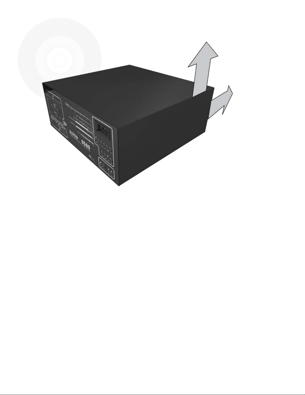
Figure 3.3 - Minimum clearance for proper airflow
3”
3”
To ensure adequate cooling
make sure the top and rear
of your amplifier have at
least 3” of clearance to allow
unobstructed airflow.
result in outlet air being drawn back into the amplifier air intake and recirculated, thus getting
hotter and hotter and resulting in degraded amplifier performance or even failure. If you are
designing your own console, consider putting in additional fans and/or ducting to deal with
waste heat. Try to minimize the possibility of dust or other contamination getting drawn into or
falling on the amplifier. It is also advisable to periodically (at least annually) clean the dust out
of your amplifier, paying particular attention to the tube fins, for continued flawless operation.
Alpha Radio Products recommends the use of compressed air for dust removal.
3.4 Antennas
Many antennas that are suitable for general use are unsuited for operation with a full 1500 W
of power. At this power level in a 50-ohm circuit, the RMS current is 5.5 amps and the peak RF
voltage is 387 volts. With a 2:1 SWR, these values double to 11 amps and 775 volts. The actual
voltage and current at various points in or on your antenna may actually be many times these
values. On a simple dipole with sharp wire ends, corona (localized ionization) can easily occur.
Corona can (and has!) led to fire in nearby objects. Traps in beams and verticals can heat up
significantly during high power operation. Instances of melting or flashover of traps have
occurred in many installations where insufficient thought has been given to their ratings. If
an antenna has been deployed for a long period of time, it may be worth taking it down for
inspection prior to full power operation. If any insulators are cracked or show signs of “tracking”,
ALPHA 9500 Interim OPERATING MANUAL
www.alpharadioproducts.com
 Loading...