

Page 1

Page 1
User Guide
for the
Alpha S9 Antenna
(S9v33+ & S9v43 versions)
Manufactured by:
Alpha Antenna
1.888.482.3249
Website: http://AlphaAntenna.com
User Guide Version 1.1
May 20, 2015
Page 2

Page 2
Table of Contents
Introduction ..................................................................................................................................... 3
Product Overview ........................................................................................................................... 3
Safety Tips ...................................................................................................................................... 3
Coax Cable ...................................................................................................................................... 4
Naturally Occuring Resonance ....................................................................................................... 4
S9 as a Dipole or 3 Element Vertical Beam Yagi ........................................................................... 5
Multi-band Operations .................................................................................................................... 5
Balun/Unun ..................................................................................................................................... 6
Ground or Elevated Mount ............................................................................................................. 6
Radials............................................................................................................................................. 8
Installation – Quick Reference ........................................................................................................ 9
How to install the tube rings (for portable use) ............................................................................ 10
How to unlatch a tube ring ............................................................................................................ 12
Installation – Detailed Instructions ............................................................................................... 12
Lowering the S9 ............................................................................................................................ 20
Disassembling the S9 .................................................................................................................... 20
Maintenance .................................................................................................................................. 21
APPENDIX 1 – Permanent installations secured by screws ........................................................ 22
Support .......................................................................................................................................... 24
Page 3

Page 3
Introduction
Thank you for purchasing the Alpha S9 Antenna hereinafter referred to as the S9. We
believe the S9 to be the lightest, most efficient and safest full-size vertical antenna
available and we sincerely hope that you enjoy your new S9.
Please read this guide in its entirety FIRST before installing your S9. The S9 is
extremely easy to install and deploy, however, reading through this guide will make it a
positive experience.
Product Overview
The S9 is a tapered, ultra-lightweight fiberglass antenna designed for fixed and portable
Amateur Radio use. Friction-locking sections and high-tech polymer tube rings allow
the antenna to be quickly and safely deployed in practically any environment without
tools. You may alternately use screws from a local hardware store to secure the
sections as provided for in the instructions in Appendix 1.
The S9 is shipped with all components you need to install the antenna. You will need
to furnish coax cable, an antenna tuner, a balun/unun, a pipe or mast with associated
hardware for your ground or elevated mount, some radials or counterpoise,
weatherproofing material, and/or other items in Appendix 1 if a permanent installation is
required.
Safety Tips
When installing or operating this antenna or any other antenna/tower, please observe the
following safety tips.
NOTE – High voltages are present when transmitting, no matter how much or little power is
applied. Do not touch any part of the antenna while transmitting.
WARNING: INSTALLATION OR OPERATION OF THIS PRODUCT NEAR POWER LINES IS
DANGEROUS! FOR YOUR SAFETY, FOLLOW THE ENCLOSED INSTALLATION DIRECTIONS. THOUGH
THIS ANTENNA IS CONSTRUCTED WITH INSULATEDMATERIALS, PROPER CARE MUST BE TAKEN
DURING INSTALLATION. INSTALLER ASSUMES ALL LIABILITY FOR PROPERTY AND LIFE SAFETY.
YOU, YOUR ANTENNA, AND SAFETY
Each year, hundreds of people are killed, mutilated, or receive severe and permanent injuries
when attempting to install an antenna. In many of these cases, the victim was aware of the
danger of electrocution, but did not take adequate steps to avoid the hazard. For your safety,
Page 4

Page 4
and to help you achieve a good installation, please READ and FOLLOW the safety precautions
below. THEY MAY SAVE YOUR LIFE!
1. If you are installing an antenna for the first time, please, for your own safety as well as
others, seek PROFESSIONAL ASSISTANCE.
2. Select your installation site with safety, as well as performance, in mind. REMEMBER:
ELECTRIC POWER LINES AND PHONE LINES LOOK ALIKE. FOR YOUR SAFETY, ASSUME THAT ANY
OVERHEAD LINES CAN KILL YOU.
3. Call your electric power company. Tell them your plans and ask them to come take a look at
your proposed installation. This is a small inconvenience, considering YOUR LIFE IS AT STAKE.
4. Plan your installation procedure carefully and completely before you begin. Successful raising
of a mast or tower is largely a matter of coordination. Each person should be assigned a specific
task, and should know what to do and when to do it. One person should be designated as the
leader/coordinator of the operation to call out instructions and watch for signs of trouble.
5. When installing your antenna, REMEMBER: DO NOT USE A METAL LADDER. DO NOT WORK
ON A WET OR WINDY DAY. DO DRESS PROPERLY: shoes with rubber soles and heels, rubber
gloves, long sleeved shirt or jacket.
6. If the assembly starts to drop, get away from it and let it fall. Remember, the antenna, mast,
cable and metal guy wires are all excellent conductors of electrical current. Even the slightest
touch of any of these parts to a power line completes an electrical path through the antenna
and the installer – THAT’S YOU!
7. If ANY PART of the antenna system should come in contact with a power line, DON’T TOUCH
IT OR TRY TO REMOVE IT YOURSELF. CALL YOUR LOCAL POWER COMPANY. They will remove
it safely. If an accident should occur with the power lines, call for qualified emergency help
IMMEDIATELY.
Coax Cable
For top performance, the S9 should be fed with a quality, low-loss 50-ohm coaxial feed
line such as RG-213 or LMR400. RG-8x is perfectly adequate for short runs of 50 feet
or less.
Naturally Occuring Resonance
S9v33+
The natural resonant frequency of the S9v33+ antenna is adjustable from 7 to 7.3MHz,
as 2 feet 4 inches of antenna element comes with 31 foot supporting structure. This
makes the total antenna element length of 33 feet 4 inches. This length also enables
the S9v33+ antenna to be used on 15 meters without a tuner, because the third
naturally occurring harmonic of 40 meters is 15 meters. Depending on the efficiency of
Page 5

Page 5
your RF ground system and proximity to nearby objects, the S9 can exhibit an SWR
well below 2:1 across the 40 and 15 meter bands without an antenna tuner.
So, if you operate a lot on 15 & 40 meters, you will likely be able to use the S9v33+ on
those bands without using an antenna tuner. In this configuration, the coax feed line
can be directly connected to the S9. Radials and a 1:1 current choke balun are strongly
recommended. As a 15 & 40 meter antenna, the S9 can be mounted on the ground or
as an elevated ground plane antenna on a pole.
Please refer to the ‘Multi-band Operations’ section of this manual for more information.
S9v43
The natural resonant frequency of the S9v43 antenna is 5.44MHz, which is the same as
traditional 43 foot aluminum verticals. This makes the total antenna element length of 43
feet. This length enables the S9v43 antenna to be used with a manual or automatic
antenna tuner, either in your shack or remotely located at the antenna feed point.
If you operate a lot on multiple bands, you will likely be able to use the S9v43 on 10 to
160 meters. Please refer to the ‘Multi-band Operations’ section of this manual for more
information.
S9 as a Dipole or 3 Element Vertical Beam Yagi
Two S9 antennas can be used to construct an Alpha S9-D (Dipole) or three S9
antennas can be used to construct an Alpha S9-VB (Vertical Beam). These user defined
and supported configurations can be found in various online forums.
Multi-band Operations
Internal rig tuners will easily tune the S9v33+ anywhere on 15 & 40 meters to a near
perfect match. If you want to use the S9v33+ or the S9v43 as a broadband antenna,
you will need a broadband antenna tuner. These would include tuners from MFJ, LDG,
and other such makers whose antenna tuners can match higher impedances. (Internal
rig tuners typically do not have adequate range to match the higher impedances
presented by the antenna on non-harmonic bands.)
Using a weatherproofed, remote antenna tuner at the antenna feed point ensures
absolute lowest signal loss and best overall multi-band performance. When a remote
tuner is used at the S9 feed point, a 4:1 unun is not required. A 1:1 current choke balun
may be required between your transmitter and the antenna (outside of the radial field) if
you experience RF current in your shack. (Burying your coax cable also helps minimize
RF current from flowing back into your shack.)
Page 6

Page 6
Balun/Unun
For multi-band use, a 4:1 “unun” from or Balun Designs is recommended at the
antenna feed point. A 4:1 unun lowers the higher impedances presented by the S9 on
frequencies above 40 meters, which can be used to lower SWRs on all bands, including
the 15 meter band where natural harmonic resonance already is already present.
Balun Designs manufactures two 4:1 ununs specifically for the S9, depending on the
amount of power you expect to run. These ununs may be purchased on-line at
www.balundesigns.com:
• If you are running 300 watts or less, use the Balun Designs 4:1 Unun (Model #
4130).
• If you are running more than 300 watts, use the Balun Designs 4:1 Unun (Model
# 4134).
For 40 meter monoband use with the S9v33+, a 1:1 current choke balun is
recommended. It should be located outside of the radial field (between your transmitter
and the antenna) to isolate RF currents from flowing back into your shack over the coax
shield. There are several commercially-available 1:1 choke baluns (Balun Designs can
be found on-line at www.balundesigns.com) or you can create a simple choke balun
using your coax feed line.
To create a 1:1 choke balun using your coax feed line, simply wind 18 to 21 feet of your
coax feed line evenly around a 4-inch round form such as a PVC pipe. You can use zip
lock cable ties to secure the windings and to maintain the coil form. Additional
information about constructing an inexpensive 1:1 choke balun using your coax feedline
can be found on-line at: http://www.hamuniverse.com/balun.html.
Ground or Elevated Mount
A pipe or mast is required for the S9 to be mounted on the ground or in the air.
For standard ground-mount installations of the 40/15 Meter S9v33+ Antenna, use
a 40-inch long (minimum recommended length), 1-1/4” (1-5/8“OD MAXIMUM)
galvanized pipe. You can also use an optional Portable Mount for temporary
installations. Hardware stores such as Home DepotTM and LowesTM stock 1-1/4”
galvanized pipe in their plumbing departments and this type of pipe is ideal for the
ground mount. Most hardware stores also have a pipe cutting machine and they will cut
your pipe to 40 inches upon request.
The 40/15 Meter S9v33+ Antenna base tube simply slips over the 1-1/4” pipe (or a
Portable Mount) and rests on the ground for an easy and elegant deployment. (A
mechanical connection from the antenna base tube to the ground mount is neither
Page 7
Page 7
required nor desired.) Do NOT use a pipe with an OD larger than 1-5/8” or it will be
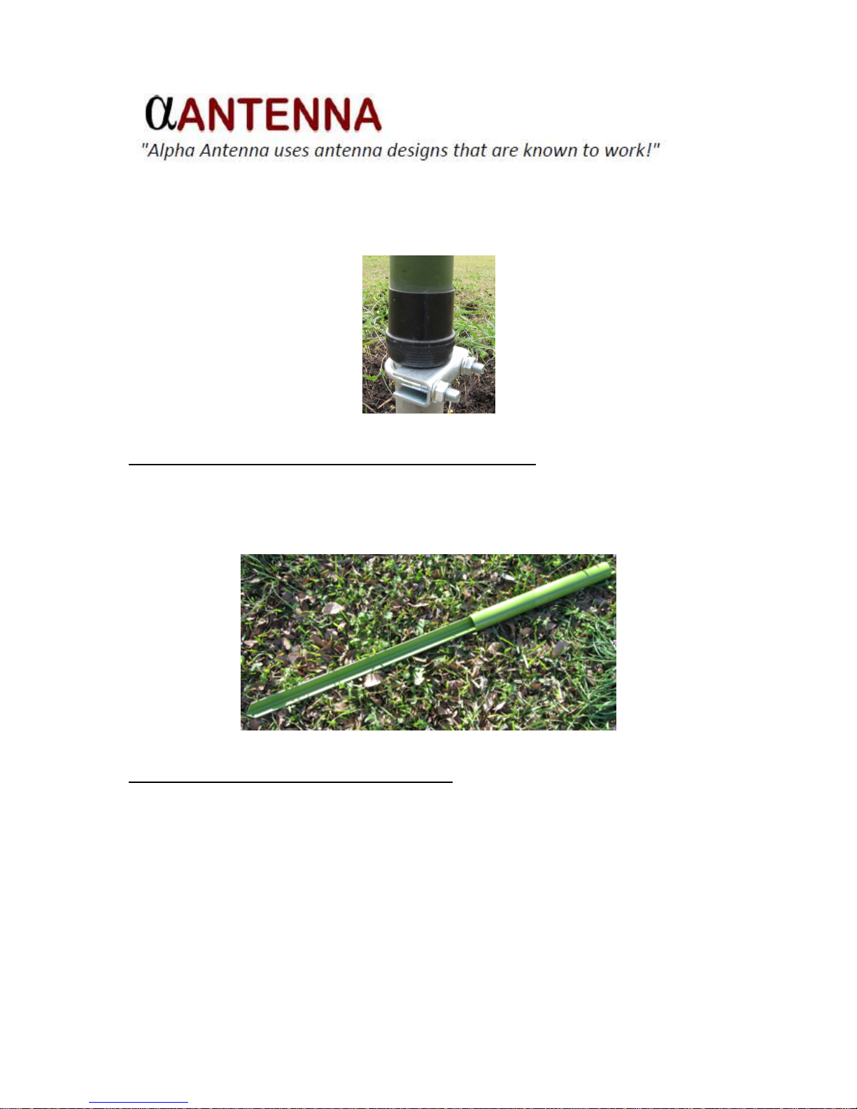
impossible to slip the S9 base tube over the pipe. An optional Pipe Mount Clamp from
your local hardware store, shown below, lets you raise the S9 base off of the ground for
a professional installation. This same technique can be matched to the different
sized diameter of the Alpha S9v43 Antenna.
Pipe Mount Clamp
For portable ground-mount operations and DXpeditions, use an optional Ground
Mount Stake available in various forms from hardware stores, similar to the one shown
below. A Ground Mount Stake similar to this would provide you with a heavy-duty
mount with an integrated stake to make ground mounting the S9 in temporary (or
permanent) locations fast and easy.
Ground Mount Stake
For elevated installations of the S9 Antenna, mount the antenna on a mast. Do not
use a mast with an OD larger than 1-5/8”, unless you are using the S9v43, in which
case you would use an appropriately matched OD for it. To create a mount for the S9
on the mast, simply install a Pipe Mount Clamp 15” from the top of the mast. The S9
will slip over the mast and rest on the flat portion of the clamp assembly. In this
elevated configuration, the S9 functions as a ground plane (GP) antenna and four
radials are required for each intended band of operation, as discussed below.
Page 8

Page 8
Radials
For optimum performance, the S9 should be used with an RF ground system consisting
of radial wires.
For ground-mounted installations, use at least 16 radials (32 preferred), with each
radial at least 0.2 wavelength at the lowest operating frequency (7 MHz) which is 26.75
feet (26 feet, 9 inches long). A ground rod is not an effective RF ground. 14 – 16 AWG
stranded insulated copper wire is recommended.
There is no precise formula to calculate the length of ground-mounted radials because
everyone has different soil and soil tends to change the electrical length of the radials.
However, a general rule of thumb for radials is: “as many as possible” and “some are
better than none”. Also, multiple short radials are better than a few long radials. If you
have the time and resources, 32 or more radials at least 26 feet, 9 inches in length (or
longer) should be considered.
For elevated installations, use four, ¼-wavelength radials for each intended band of
operation. For example, you should have four ¼-wavelength radials for 40 meters, four
¼-wavelength radials for 20 meters, and so on. Attach the radials to the optional S9
Pipe Mount Clamp below the base of the antenna and try to position the radials
equidistantly around the S9 base. The radials may lie flat or droop up to a 45-degree
angle down from the base of the antenna. Attach insulators to the ends of the radials.
Connect your coax shield to the clamp and radials. Do NOT run a wire from the
radials/clamp/coax shield to an earth ground.
Page 9
Page 9
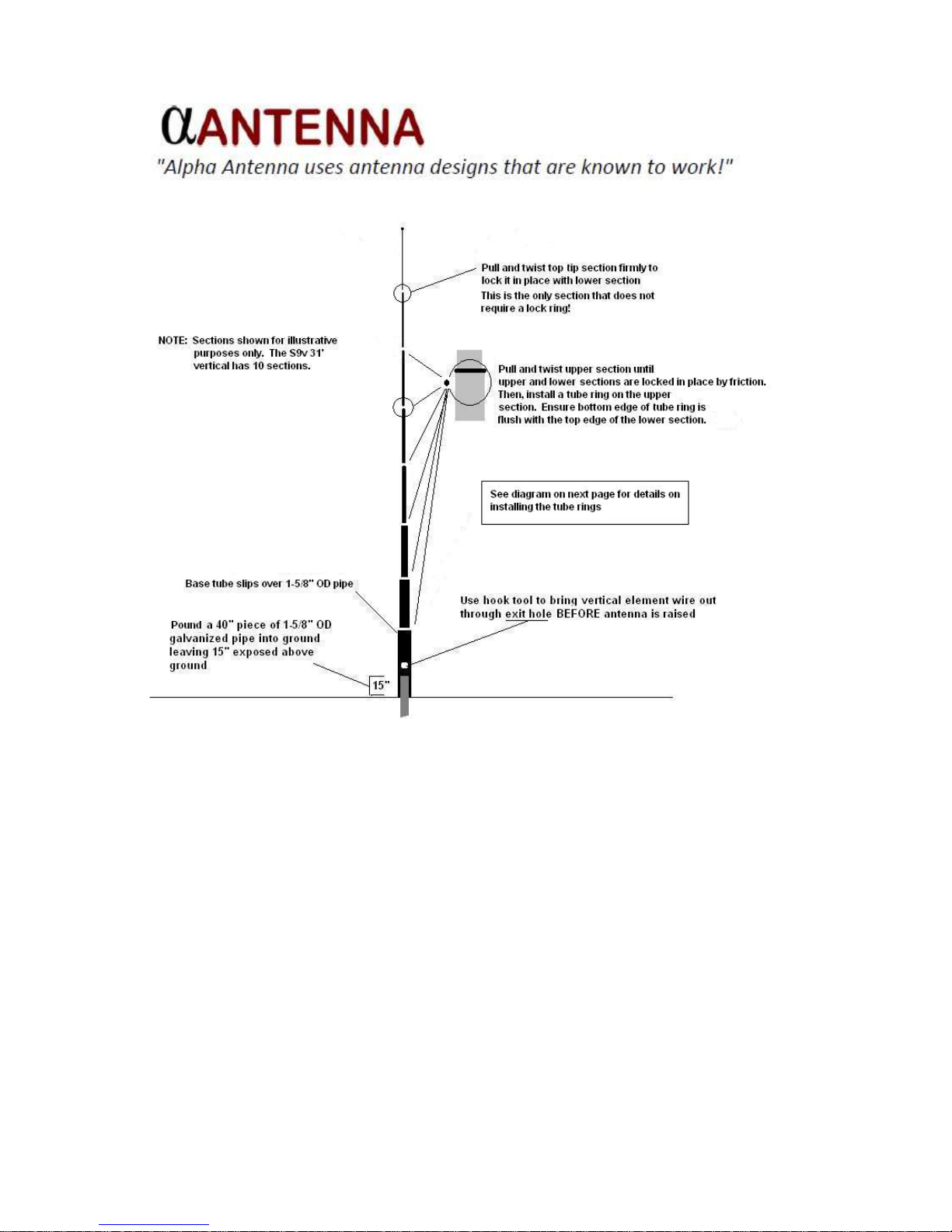
Installation – Quick Reference
Page 10
Page 10
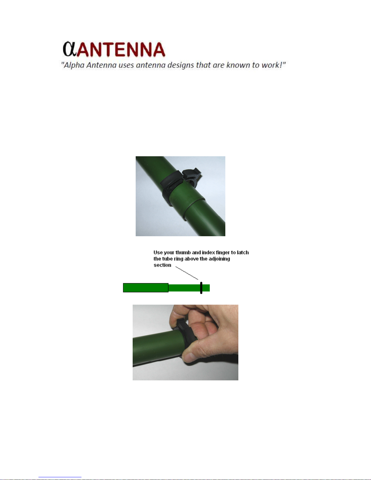
How to install the tube rings (for portable use)
-
The polymer tube rings are not clamps – they are “stops” and are used to keep the
associated tube section from collapsing down into the tube immediately below it.
-
Slide a tube ring over the tube and use your thumb and index finger to loosely latch the
ring about 15 to 20 inches above the adjoining, lower tube.
Page 11
Page 11
-
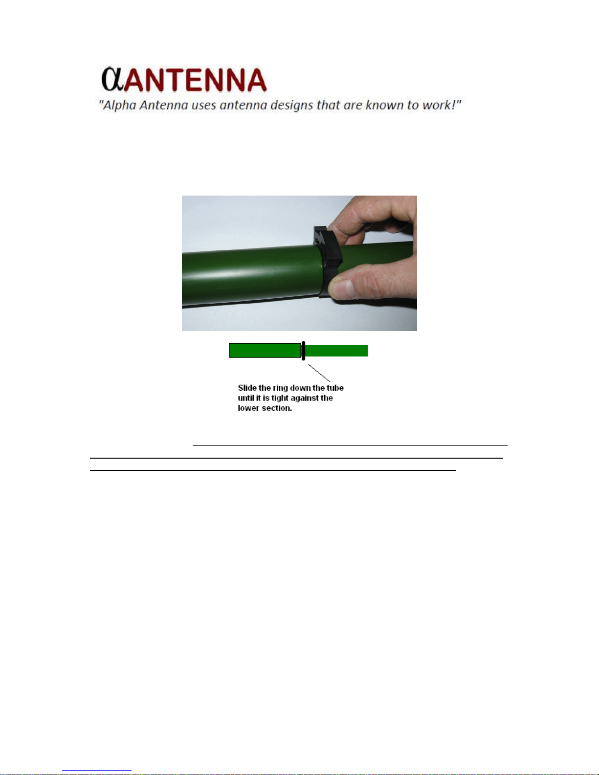
Next, slide the ring down the tube to see if it fits tightly against the top edge of the
adjoining lower tube.
-
If the ring is not tight, slide the ring back up the tube, use your thumb and index finger to
advance the latch ONE MORE CLICK. Repeat the previous step and this step until the
ring fits tightly against the top edge of the lower tube section as shown above.
-
Once a tube ring is properly latched, there is no need to unlatch or change the ring latch
setting – simply slide the rings on and off the tubes each time you assemble or
disassemble the antenna.
Page 12
Page 12
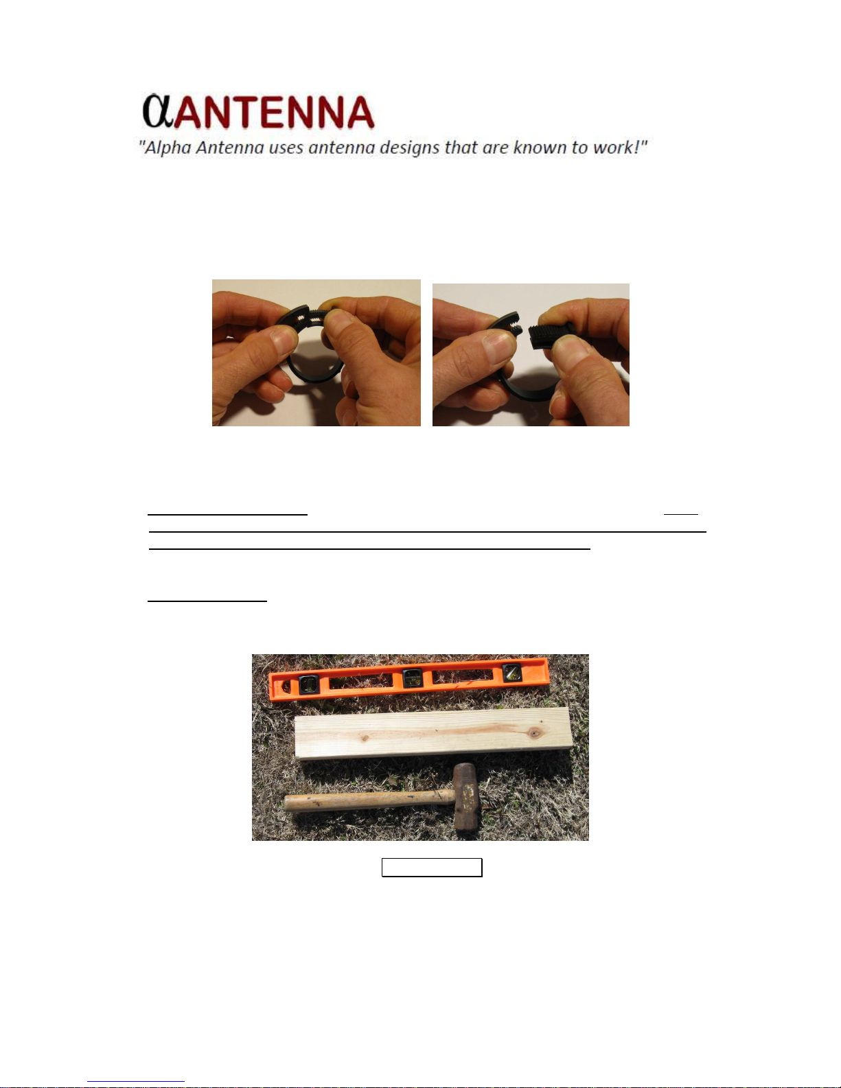
How to unlatch a tube ring
Unlatching a tube ring is easy! Use both hands. Push forward on one tab while pulling
back on the other tab to free the latching mechanism, as shown below.
Installation – Detailed Instructions
1. Select Installation Site. Try to use a clear and open area to deploy the S9. Even
though the S9 is completely insulated, you absolutely MUST locate the antenna site
at least 46’ away from power lines (1.5x the length of the antenna). In fact, an ideal
installation site would be a least 46’ away from any other large object such as a
house or trees.
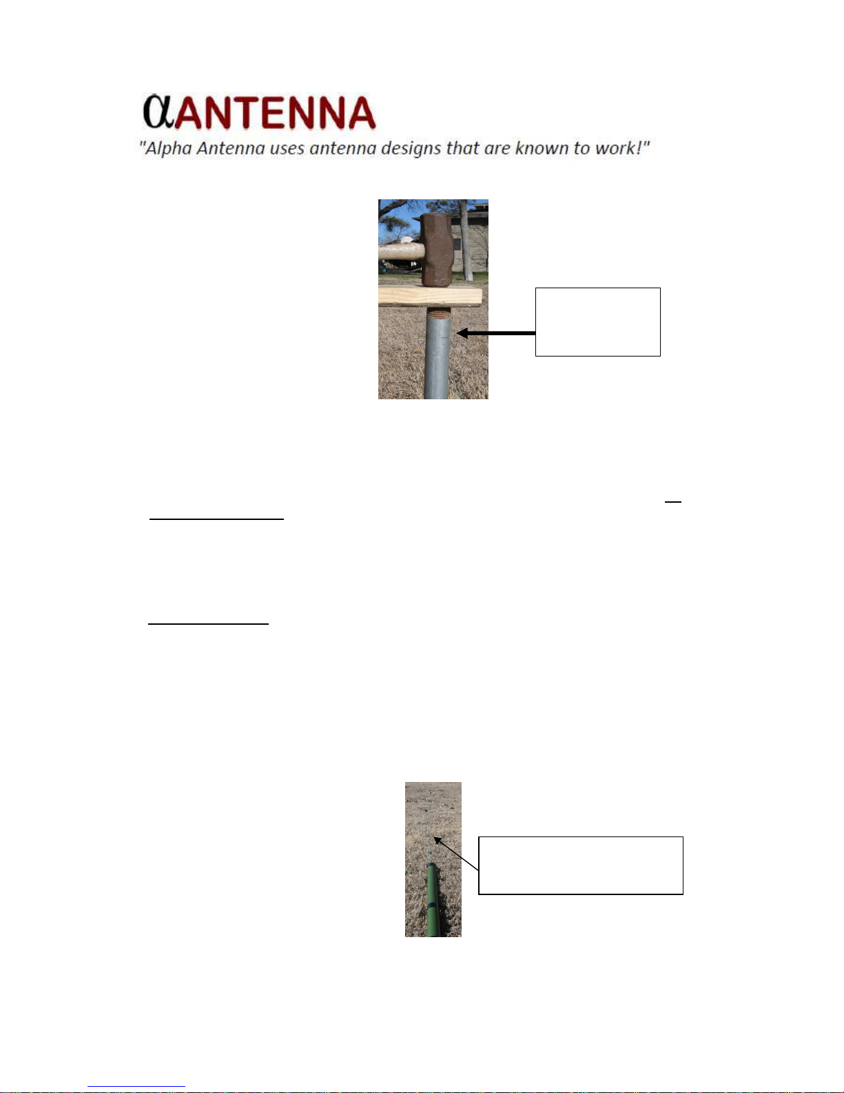
2. Install the Mount. The S9 requires a mount. The elevated mount was discussed
earlier. For ground-mount installations, you will need a large hammer, a spare piece
of wood and a level.
IMPORTANT!
Place a piece of wood over the top of the pipe or Portable Mount to protect the
top edges from becoming deformed. Hammer the piece of wood in a straight
Page 13
Page 13
downward direction. Do NOT directly hammer the pipe or Portable Mount
metal – hammer the wood to protect the pipe/mount.
NOTE: Use a level while you are installing the pipe or Portable Mount to
ensure that it is as straight as possible in the vertical plane.
Drive the 1-1/4” (1-5/8” OD MAX) x 40-inch long pipe into the ground leaving 15
INCHES MAXIMUM above the ground. If you use an optional Pipe Mount Clamp,
mount it on the pipe an inch or two above the ground.
If you are using an optional Portable Mount, drive the stake into the ground until the
bottom of the mount is flush with the ground.
3. Assemble the S9.
a. Lay the S9 on the ground near the ground mount and unwind the vertical
element wire from the base tube. Now, “walk the wire” away from the antenna
base tube in a straight line. Don’t pull unnecessarily on the wire – the idea is to
un-roll the wire to its full length. Once the wire is completely unrolled, pull small
sections of the wire through your hands to straighten the wire. NOTE: The wire
does NOT have to be perfectly straight, so don’t spend a lot of time trying
to straighten the wire!
Pull wire straight out from
base tube until it is fully
extended along the ground
15 inches
maximum from
ground to top of
pipe
Page 14
Page 14
b. Next, remove the TOP rubber plug. Do NOT remove the BOTTOM plastic end
cap where the wire exits. Put the top rubber plug in your pocket so that it will not
be lost in the grass.
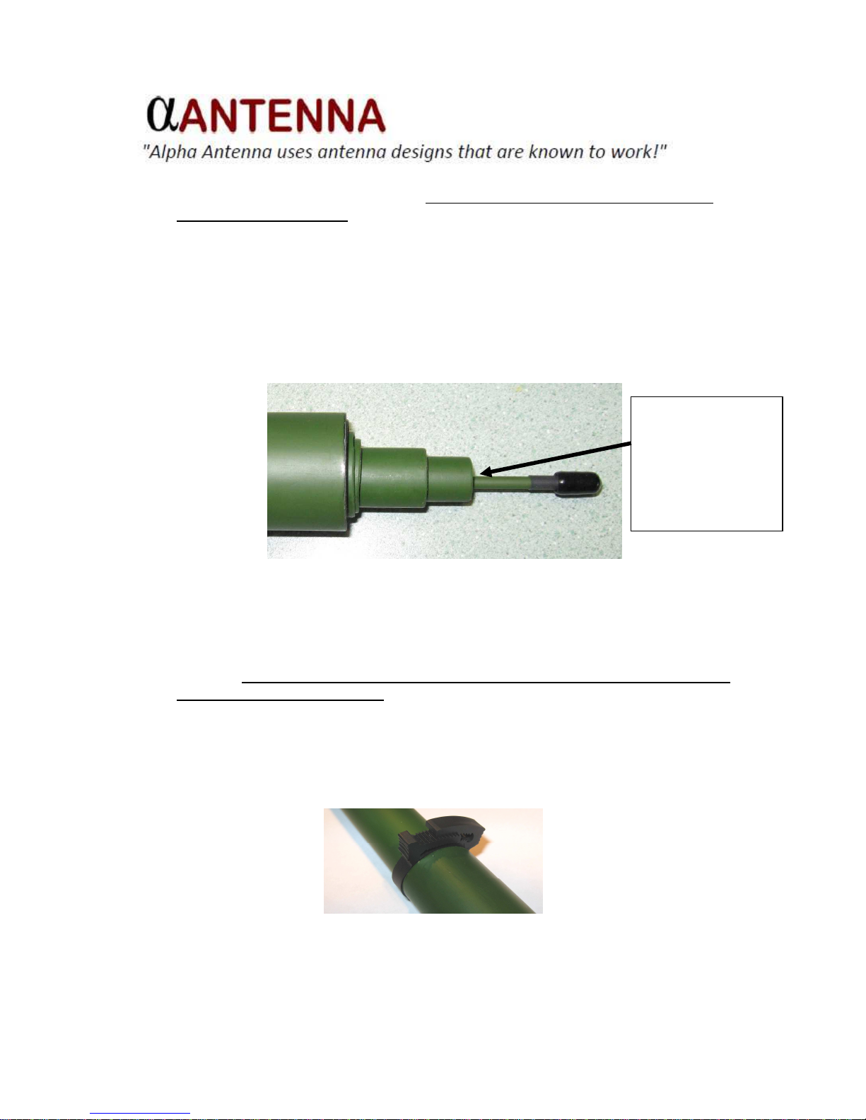
c. Now we are ready to extend the antenna sections. The S9 should still be laying
flat on the ground. To extend the antenna, grab a section of the wire near the
bottom end cap and push the wire into the base tube. This action should cause
the top, thinnest section of the antenna (it has a cap on its tip) to pop out of the
top of the base tube. (If this doesn’t work, pick-up the base tube and shake it
slightly while pointing the top part of the tube downward.)
d. Gently pull the top, thinnest section straight out of the base tube (pull the section,
not the cap) until it catches and pulls the next, lower section out. Gently twist
the top section to lock it into the lower section. Now, pull the lower section
straight out until the next section appears. Repeat this until you have extended
all the sections from the base tube. Pull and twist the sections to friction-lock
them but do not overdo it as it may be difficult to collapse the sections later
on if they are over-extended.
e. As shown below, each upper tube section (except the top, tip section) requires a
polymer tube ring to prevent the tube from collapsing down into the larger
diameter tube immediately below it.
Grab
top section
here (not the cap)
and pull straight out
to retrieve the next
section. Repeat until
all sections are
extended from the
base tube.
Page 15
Page 15
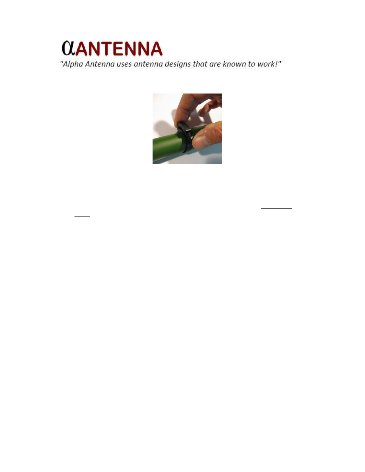
f. To install a ring, slide it over the top of each upper section and use your thumb
and index finger to squeeze the ring tabs until the teeth click together, as shown
below.
g. Next, slide the ring down the tube toward the lower, larger tube section. All tube
diameters are tapered, so the goal is to have the ring fit tightly against the top of
the adjoining lower tube section. You may have to slide the ring back up the tube
(where the diameter is smaller) to advance the ring latch another click and then
slide the ring back down the tube before you find the perfect fit. Do not use
pliers! This process is easily done by hand. Use sense of touch to determine
when a ring is tight enough to keep the associated tube from collapsing.
NOTE: Unlatching a tube ring is easy! Use both hands. Push
forward on one ring tab while pulling back on the other tab
to free the latching mechanism.
h. The top tip section does not require a tube ring. To secure the top section, hold
the section below it with one hand and firmly twist and pull the tip section with
your other hand until it is firmly friction-locked in place.
NOTE: The antenna should now be fully extended and laying on the
ground and all sections (except the top section) should have
the tube rings installed.
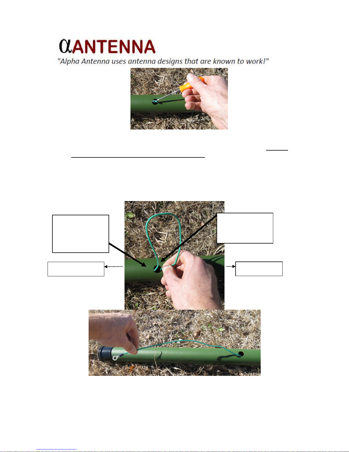
i. Now, let’s retrieve the vertical element wire from the base tube. Rotate the base
tube until you see the wire exit hole.
j. Using a hook, as the example in the next image portrays, grab the wire and pull a
small U-shaped portion of the wire through the exit hole, as shown in the next
image.
Page 16
Page 16
Once you get a small U-shaped portion of the wire out of the exit hole, you can
gently twist it, if needed, to help retrieve the wire. Now STOP and carefully
remove the wire from the hook. Next, hold the top part of the wire firmly in one
hand while you use your other hand to pull the lower, loose end of the wire out
through the hole. Do not pull on the top part of the wire – just pull on the lower,
loose end!
1.
Hold top part of
wire firmly. Do
not pull on this
part of the wire.
2. Use
your
other
hand to pull the
loose end of the
wire out of the
base tube
Top of Antenna
Bottom of Antenna
Page 17
Page 17
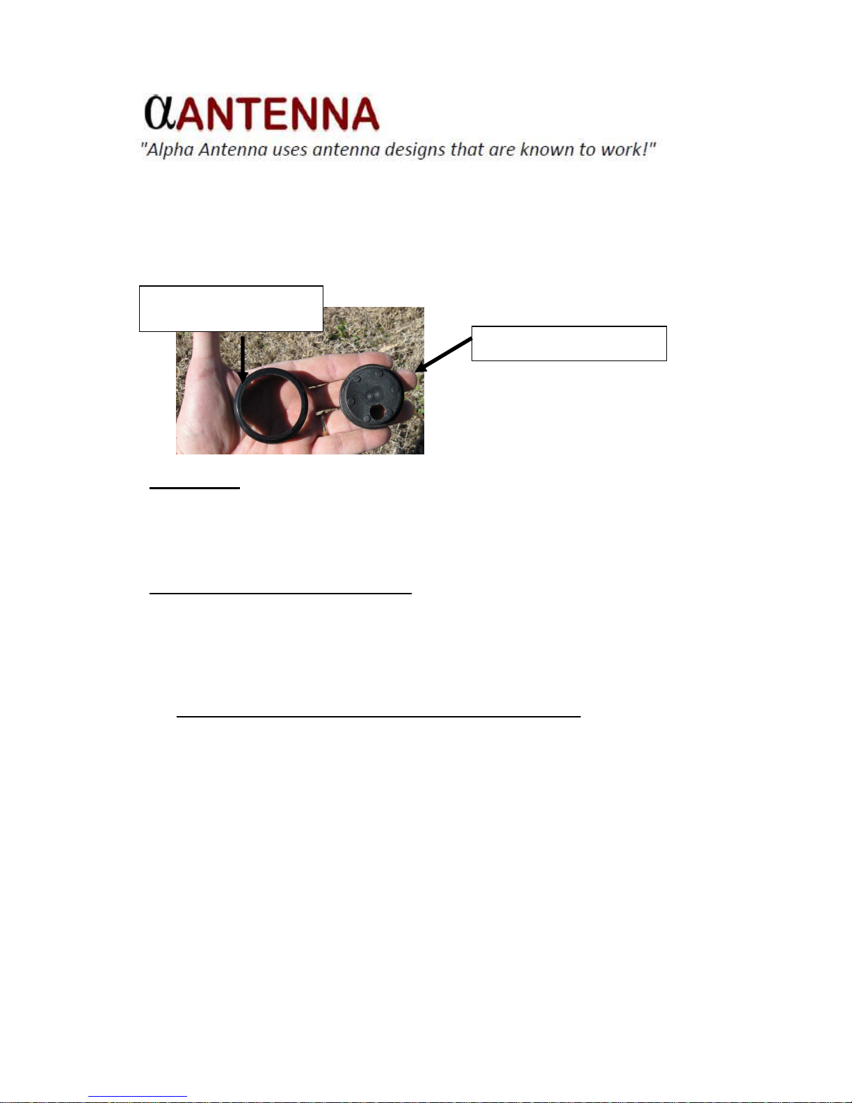
k. Before we raise the antenna, unscrew the bottom end cap. This cap consists of a
center piece and plastic ring. Remove the center piece and put it in your pocket.
Now screw the ring back onto the bottom of the base tube. The ring will protect
the base tube bottom cap threads while the antenna is deployed and it also
creates a drain path for any moisture that accumulates inside the fiberglass
sections.
4. Raise the S9. This is the fun part! To raise the S9, simply grab the base tube with
one hand and the next section with your other hand and raise the antenna. Next,
center the antenna directly over the pipe or Portable Mount and then gently lower
the S9 down until the bottom of the base tube rests on the ground or pipe mount
clamp.
5. Connect Coax Feed Line to Antenna.
If you are using the S9 as a 40 meter mono-band vertical, proceed with step “a”,
below.
If you are using the S9 as a multi-band antenna (40 – 6 meters), skip to step “b”.
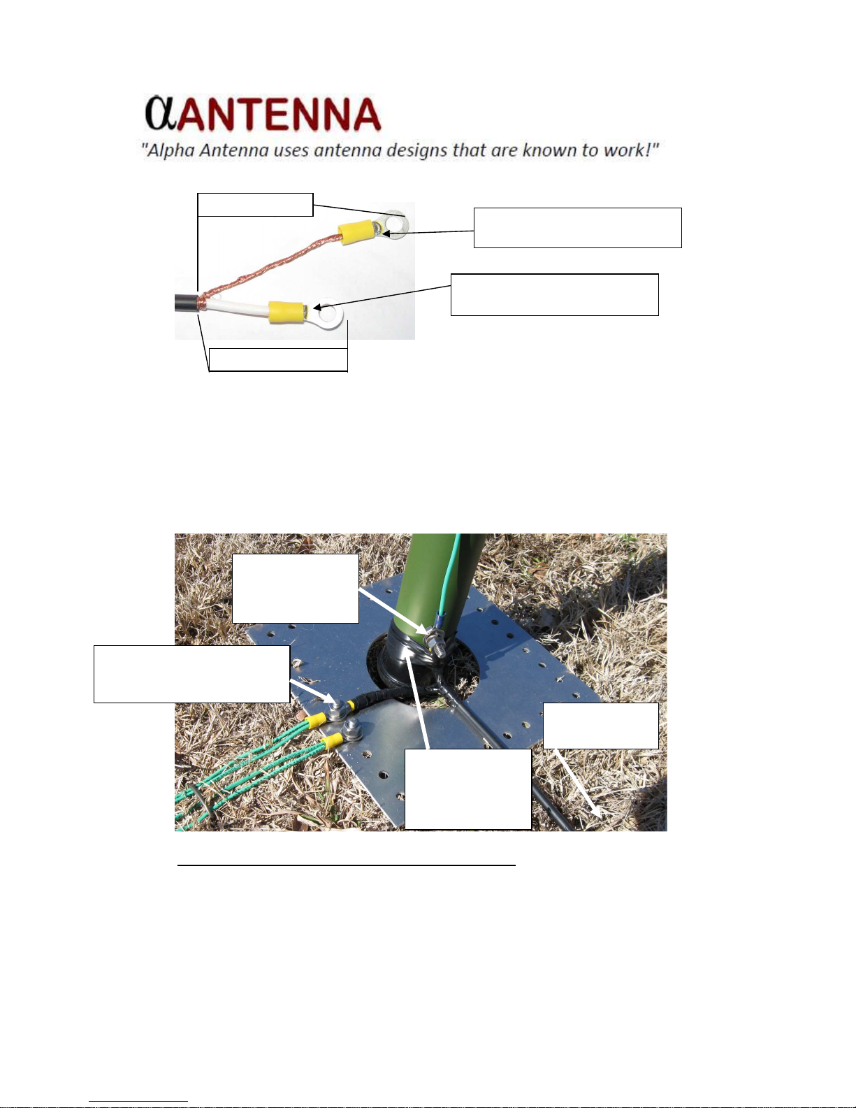
a. If you are using the S9 as a 40 meter monoband vertical, position a 1:1
choke balun in-line with your coax feedline, outside of the radial field. Then,
solder two ring terminal connectors to the antenna end of your coax feed line. To
prepare the coax, remove about 3 inches of the coax outer jacket. Leave the
braid 3 inches long and trim back the center connection to around 1-1/2 inches
long. Then, solder the center and shield coax connections to your ring terminals.
1. Remove cap center piece
2. S
crew
plastic ring
back
onto the base tube
Page 18
Page 18
Refer to the picture below. Wrap some electrical tape around the coax center
and shield. Then, using stainless steel hardware, connect the coax center
connector to the S9 vertical element wire. (The bolt head should face the base
tube, as shown below.) Secure the coax center lead to the bottom of the base
tube with electrical tape.
Next, connect the coax shield to a convenient hole on a homemade or
commercially available radial plate. Now, skip to step “c”.
b. If you are using the S9 as a multi-band vertical, position a 4:1 unun (or
remote antenna tuner) at the base of the S9 and connect the S9 vertical element
wire ring terminal connector to the active element unun connector marked (or to
the remote antenna tuner connector marked Antenna).
Solder
Coax
Shield
to Ring
Terminal
Solder
Coax
Center
to Ring
Terminal
About 3 Inches
About
1-1/2
Inches
Connect coax
center to S9
vertical element
wire
Connect coax shield to any
convenient point on any
radial plate
Wrap
electrical
tape around coax
center lead to
secure it to the
base tube
Coax to 1:1
choke balun
Page 19
Page 19
Next, solder two ring terminal connectors to a short piece of radial wire or copper
braid and connect the unun Radials stud (or remote antenna tuner Ground
connector) to the nearest hole on a radial plate. Finally, connect your coax feed
line PL-259 male connector to the 4:1 unun (or remote antenna tuner) SO-239
female connector.
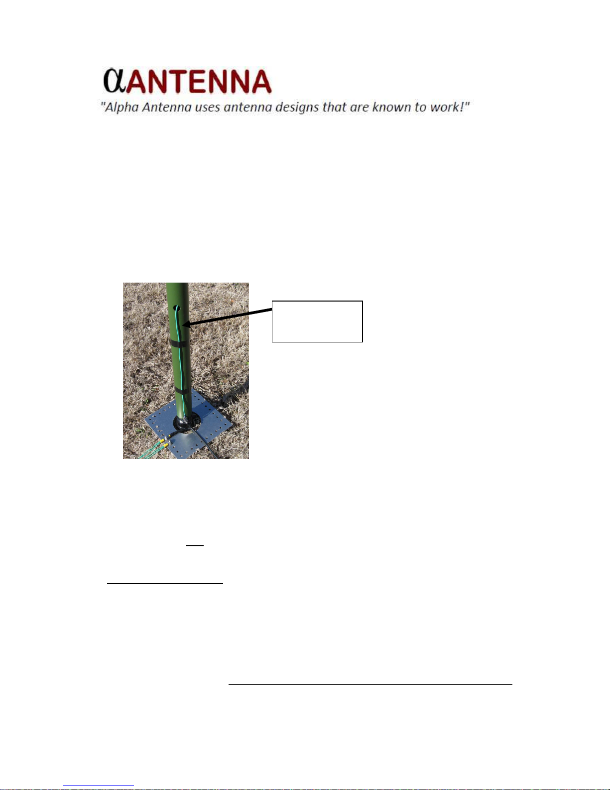
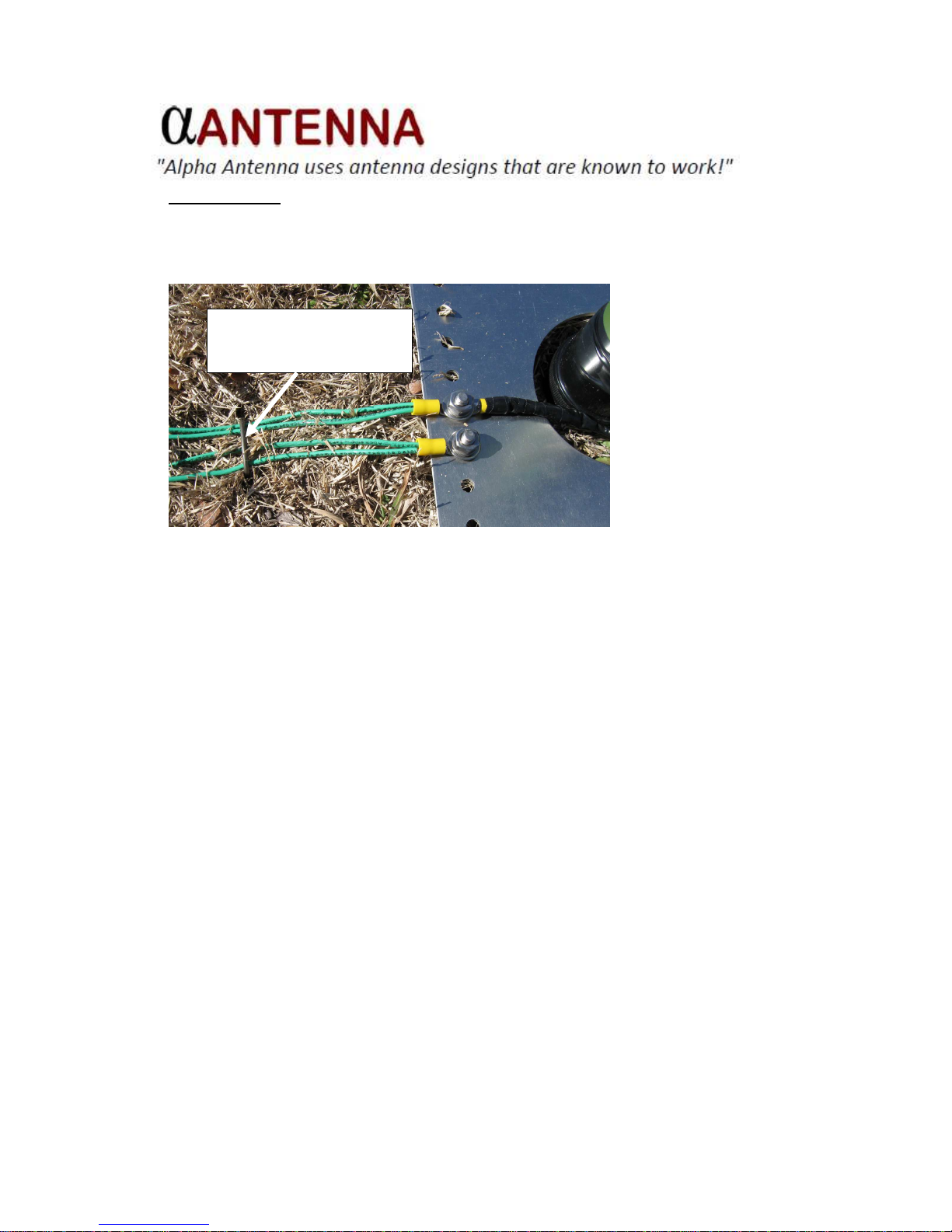
c. You can use electrical tape or zip ties to secure the vertical element wire
below the base tube exit hole. If there is any slack in the vertical element
wire, it should to be left ABOVE the electrical tape or ties. This way, there
will be some slack wire available to move with the fiberglass sections in the
event of very strong wind.
d. COMPLETELY weatherproof the vertical element wire connection and all coax
feed line and unun connections using the sealant of your choice such as coax
seal, silicon RTV, etc.
NOTE: It is not necessary to weatherproof the ring terminal
connections on your radial plate.
6. Install Ground Radials. For ground-mount installations, we suggest a minimum of
16 radials, each at least 26 feet, 9 inches long spaced as evenly as possible around
the S9 base – like wheel spokes. For best performance, use 32 (or more) radials.
It is suggested that you use 14 – 16 AWG insulated stranded copper wire (available
at Home DepotTM and sold in 500-ft rolls). Your hardware store will also sell ring
terminal connectors to facilitate connecting the radial wires to the radial plate.
Use lawn and garden fabric staples (sold at Home DepotTM or LowesTM) to secure
the radials to your yard. Install the first staple about 3 inches or so from the edge of
Leave
wire slack
above tape or
ties
Page 20
Page 20
the radial plate. Grass will eventually grow over the radials and cover them. In the
meantime, be sure to set your lawn mower blade a little higher than normal to
ensure that the radials do not get caught in the mower blade. It is best to use at
least 8 staples per radial to ensure the radials are held firmly against the ground.
Lowering the S9
The antenna should perform in winds up to around 40 MPH. Ice is definitely a concern
for any antenna. If winds above 40 MPH and/or ice are expected, you should lower the
antenna to protect it from becoming damaged.
To lower the S9, simply disconnect the vertical element wire from the coax center
connection (or unun/remote antenna tuner) and carefully lift the antenna straight up off
of the mount. Then, gently lower the antenna to the ground.
NOTE: If the wind is strong, it is easier to lower the antenna with the
wind at your back.
Disassembling the S9
To disassemble the S9:
1. Disconnect the vertical element wire from the coax center connection or unun.
2. Carefully lift the antenna off of the ground mount and gently lower it to the ground.
3. Remove the black plastic end cap ring from the base tube and insert the rubber
center piece back into the ring – we will put this cap back on in a few steps, so put
this into your pocket for now.
4. Carefully bend and push the connector end of the vertical element wire back through
the exit hole and into the base tube.
Install first
radial
staple
about 3 inches from the
edge of the radial plate
Page 21

Page 21
5. Slide ALL tube rings off of the fiberglass sections and put them in a zip lock bag for
future use.
6. Now, collapse the antenna sections. Hold the base tube firmly in one hand and grab
and twist the section above the base tube while pushing it toward the base tube until
the tube collapses into the base tube.
7. Before collapsing any other sections, pull the vertical element wire out of the bottom
of the base tube.
8. Thread the wire through the small hole in the end cap center piece and then screw
the bottom end cap back onto the base tube.
9. Stay at the base tube and collapse the remaining antenna sections one-by-one by
twisting and pushing them into the base tube.
NOTE: Be sure to keep an eye on the vertical element wire to ensure
that it does not get caught in any of the collapsing sections.
10. When all of the sections are in the base tube, push the rubber end cap
into the top of the base tube.
11. You may use a VelcroTM strap to secure the vertical element wire to the
base tube and you’re ready to go!
Maintenance
The S9 features an enhanced, durable painted surface. If you notice surface oxidation
(color becomes lighter), use a soft cloth and Armor AllTM to restore the finish.
Automotive spray wax is also an excellent product to seal and protect the finish. The S9
may also be repainted, if desired, using a quality exterior spray paint such as KrylonTM
or RustoleumTM. It is suggested that you lightly dull the finish and then prime it with a
quality primer before you paint it.
Page 22
Page 22
APPENDIX 1 – Permanent installations secured by screws
You will need seventeen “course thread” stainless steel screws that are either 1/4 or 1/2
inch long that are approximately 1/8 inch wide. Before you begin, gently pull the top
thinnest section straight out of the base tube (pull the section, not the cap) until it
catches and pulls the next, lower section out. Gently twist the top section to lock it into
the lower section. Now, pull the lower section straight out until the next section
appears. Repeat this until you have extended all the sections from the base tube. Pull
and twist the sections to friction-lock them all.
The bottom section will have four screws, the middle sections have two screws and the
top three sections have one screw each.
The top tip section does not require a screw. To secure the top section, hold the section
below it with one hand and firmly twist and pull the tip section with your other hand until
it is firmly friction-locked in place.
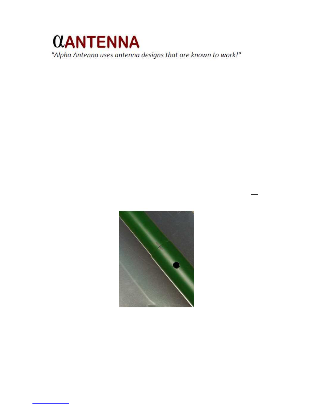
As the picture below depicts, make black marks with an indelible black marker that will
align the screw holes you are marking. Now, start by drilling with a smaller bit than what
you require and step your drill bits up while making holes to support each section. Be
careful not to drill through both outer tube walls!
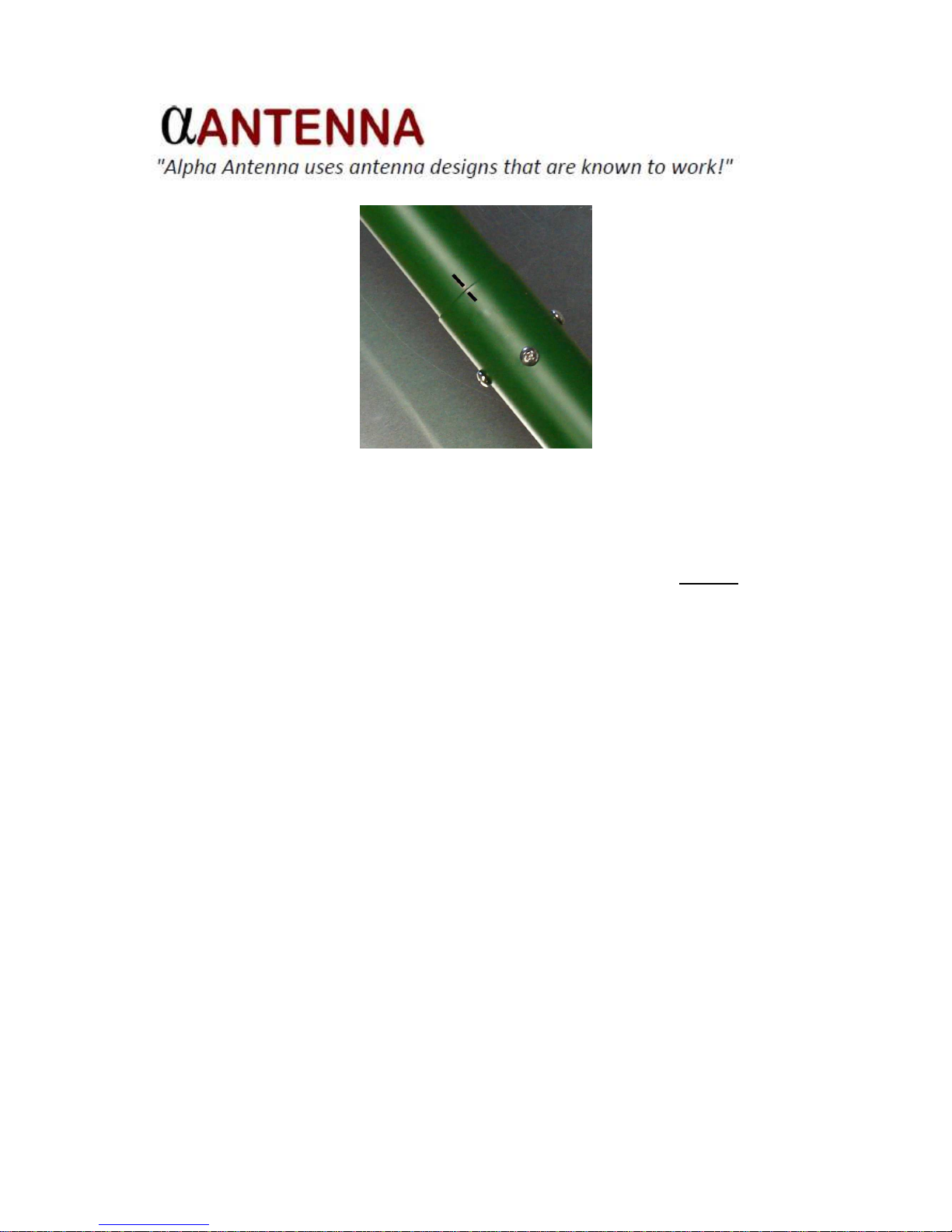
As mentioned, each tube section (except the top, tip section) requires screws for
permanent base mounting to prevent the tubes from collapsing down into the larger
diameter tubes immediately below it. Your antenna is now prepared to have the screws
affixed, into each of the holes you have pre-drilled, as the following image of the base
section shows.
Page 23
Page 23
Continue with securing each section with their appropriate screws until all sections have
been secured. Again, the bottom section has fours screws, the middle sections have
two screws and the top three sections have one screw.
The antenna should now be fully extended and laying on the ground and all sections
(except the top section) should be secured with screws. Now, return to Step 3 i to
continue installation.
Page 24

Page 24
Support
If you have any questions or problems installing your S9, please contact us.
You can reach us via:
Email – [email protected]
Phone – 1-888-482-3249
Web – www.AlphaAntenna.com
Our mailing address is:
Alpha Antenna
102 East Main Street
Building E
Greenwood, MO 64034
 Loading...