

Page 1
Power
Alpha XP-EDH-A2 Transponder Field Installation Instructions
CAUTION!
A grounded Surge Protector (Alpha P/N 162-028-10) or equivalent) is required for all installations.
Do not place the transponder on top of the power supply or the batteries.
Make all battery harness connections to the batteries and connect the interface cables to the power supply before connecting the cables to the
transponder.
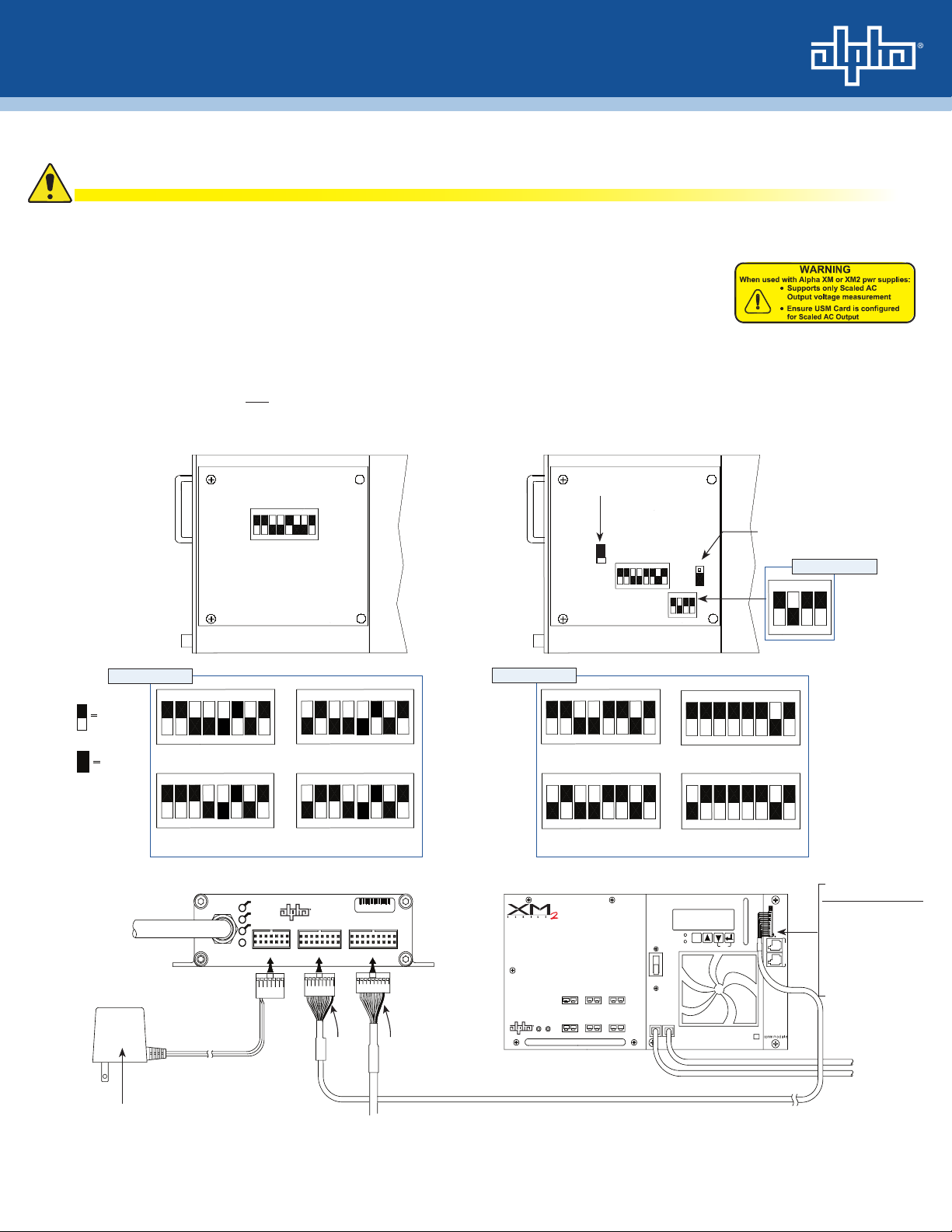
First, verify the transponder bears the warning label as shown at right. This indicates the unit is an XP-EDH-A2,
and the jump and switch settings described in this instruction will work properly.
Verify the transponder's MAC address is loaded into the CMTS, and DOCSIS conguration le options should be
set. Detailed instructions for eld installation procedures are available in the XP-EDH-A2 Technical Manual
(Alpha P/N 745-838-B2) available at www.alpha.com.
Alpha XM Series 2 Power Supply
1. Switch the battery breaker OFF.
2. Remove the Inverter Module from the power supply. See the power supply's technical manual for instructions.
3. Position jumpers and switches as shown below.
USM2.5
SW1
ON
SW1 Settings:
Power
14 PIN
ON
48V and <20A
ON
48V and ≥ 20A
AlphaNet
DOCSIS Transponder
Power Supply
16 PIN
Black
wire
To Battery Harness
0A C4 36
Battery
18 PIN
ON
ON
JUMPED
<48V and <20A
ON
<48V and ≥ 20A
PWR
ONLINE
US
DS
System RF Cable in
AC voltage input (USM2 cards only)*
* CBL-PS-PWR-01-001 120V p/n: 875-563-10
CBL-PS-PWR-03-002 220V p/n: 875-562-10 (3' cord with IEC C13 connector and 220V US NEMA 6-15 plug)
Yellow
wire
USM2
(AC Scaling of
JP2: 2-3 Jumped
Output Voltage)
1
2
3
SW1 Settings:
ON
<48V and <20A
ON
48V and <20A
OUTPUT 2
N + 1
OUTPUT
SSR
N
Power Supply Interface Cable
cbl-ps-intfc-01-003, Alpha p/n: 875-565-10
LRI
L
OUTPUT 1
WHT
SW1
ON
transformer
m o d u l e
BLK
SW2
inverter
module
BATTERY
BREAKER
BATTERY
INPUT
BLACK
ON
ON
<48V and ≥ 20A
ON
48V and ≥ 20A
UNLATCH RIBBON CABLE RETAINER
BEFORE FULLY REMOVING MODULE.
OUTPUT
ESC
ALARM
RED
TEST
JP1 (5V Position)
ON
TMPR
S
Y
S
C
O
M
TEMP
PROBE
SW2 Setting:
Important!
Plug in the 13 pin
connector so that the
black wire is in pin 1 (the
bottommost pin) and two
open pins are left at the
top for tamper switch
connector.
RED
To Batteries
BLACK
1745-838-C5-001 Rev. A
Page 2
Power Supply
PWR
Power
14 PIN
US
DS
Battery
18 PIN
16 PIN
Fuse
WARNING:
3
INDICATOR
LAMP
REMOTE
STATUS
RELAY
STANDBY
1 2
OUTPUT
4 65
AC
BLACK
RED
BATTERY
CONNECTOR
+
CIRCUIT
BREAKER
-
BATTERY
OFF
BLACK
RED
DOCSIS Transponder
AlphaNet
0A C4 36
ONLINE
System RF Cable in
AC Voltage Input
120V p/n 875-563-10
220V p/n 875-562-10
To Battery Harness
Power Supply Interface Cable
p/n 875-565-10
Black
wire
Yellow
wire
To Batteries
18 PIN
Battery
Black
wire
Red/Green
wire
View
Side
Cut
Here
CUT AND REMOVE A PIECE OF
RED/GREEN WIRE IF PRESENT
FOR XM SERIES ONLY
!
CUT THE WIRE
IN UPPER LEFT POSITION
AS SHOWN. ANY WIRE COLOR.
120VAC
TO
9VAC
3 FT CORD
NEMA 6-15P
220V US
220VAC
IEC C13
9VAC
TO
CBL-PS-INTFC-01-003
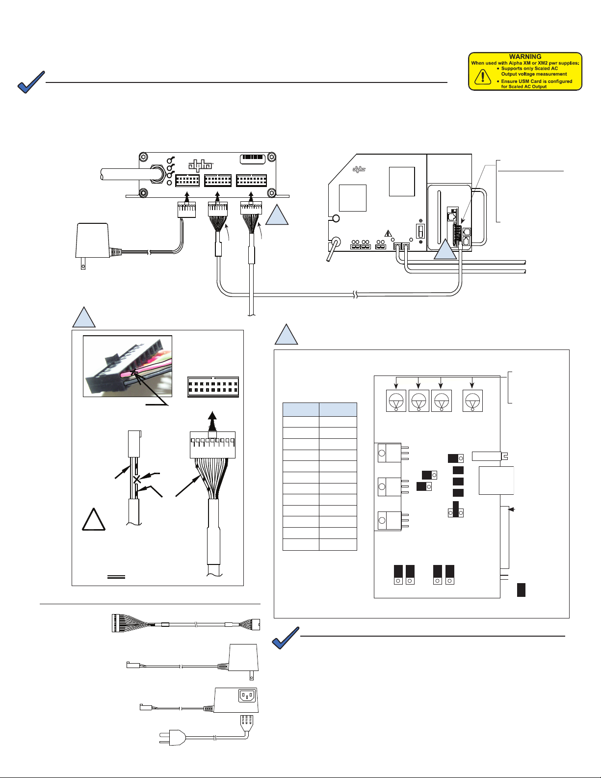
Alpha XM Series Power Supply
First, verify the transponder bears the warning label as shown at right. This indicates the unit is an XP-EDH-A2, and the
jump and switch settings described in this instruction will work properly.
NOTE:
A chipset upgrade to the XM Inverter Module and/or USM Card may be required; contact Alpha for
more information.
Set the jumpers and calibrate the USM card before making cable connections and applying load.
1. Switch the battery breaker OFF.
2. Remove the Inverter Module from the power supply. See the power supply's technical manual for instructions.
3. Position jumpers and switches as shown below.
A
B
A
Important!
Plug in the 13 pin
connector so the black
wire is in pin one (the top
pin) and two open pins
are left at the bottom for
tamper switch connection.
Necessary Cables
CBL-PS-INTFC-01-003
Alpha P/N 875-565-10
CBL-PS-PWR-01-001
Alpha P/N 875-563-10
Or
CBL-PS-PWR-03-002
Alpha P/N 875-562-10
B
Remove the USM and
set the jumpers as shown
below:
Jumper Position
P1 2-3
P2 open
P3 open
P4 closed
P5 closed
P6 closed
P7 5V
P8 1-2
P9 1-2
P13 1-2
P14 1-2
SW4 0
SW1
P8
1
2
3
DC
USM
SW2 SW3 SW4
P3
3
12
12
AC Volts
P13 P14
1
2
3
P4
P5
P6
P7
24V 15V
P9
AC
CUR
P1
P2
1
2
3
12
R8
1
1
1
5V
1
2
3
NOTE:
The EDH-A2 calculates Output Voltage using AC Scaling as opposed
to the EDH-A which uses DC Scaling. This requires changes to the
USM card jumper settings and eliminates the need to calibrate the USM
potentiometer.
Set to 0
(SWs 1,2,3 may not
be present on some
boards)
Potentiometer
Adjuster
RJ Connector
PIN 1
Power Supply
Interface
= Jumped
2745-838-C5-001 Rev. A
Page 3

Alpha AM/AP Series Power Supply
120VAC
TO
9VAC
3 FT CORD
NEMA 6-15P
220V US
220VAC
IEC C13
9VAC
TO
ZTT
ZTT
+
ZT
T+
SILVER
GROUND
TA
M
P
E
R
B
L
ACK
CBL-PS-INTFC-02-005
9VAC
120VAC
TO
220VAC
NEMA 6-15P
220V US
9VAC
3 FT CORD
IEC C13
TO
Power Supply
PWR
Power
110V AC Line Input
14 PIN
ONLINE
US
DS
16 PIN
CBL-PS-INTRFC-01-001
Battery
CBL-PS-BAT-04-004
18 PIN
DOCSIS Transponder
AlphaNet
R
0A C4 36
BLACK
RED
C
BL-PS-
I
N
T
R
FC-
01-002
Alpha
S
E
R
I
E
S
T
e
chno
l
ig
i
es
AM/AP
1
2
3
4
5
6
7
8
9
10
NO
COM
NC
LAMP
OUTPUT
BATT
+
-
RED
BLACK
0A C4 36
DOCSIS Transponder
AlphaNet
To Battery Harness
Power Supply Interface Cable
p/n 875-566-10
To Batteries
System RF
Cable in
Ground
Tamper
Power Output Cable with transformer
120V p/n 875-718-10, 220V p/n 875-717-10
To Load
Switch the battery breaker OFF.
NOTE:
• The power supply must be disconnected from line voltage during installation.
• If not already installed, install an RPM card. Refer to RPM instructions for details.
Necessary Cables
N
EUT
HOT
CBL-PS-INTRFC-01-002
CBL-PS-INTFC-01-002
Alpha P/N 875-564--10
Note:Rev. B of this cable does
not have a Violet wire
CBL-PS-PWR-01-001
Alpha P/N 875-563-10
Or
CBL-PS-PWR-03-002
Alpha P/N 875-562-10
CBL-PS-INTFC-01-002
Alpha P/N 875-564-10
Important!
Plug in the 13 pin connector so the black wire is in pin
one (the right-hand pin) and two open pins are on the
left for tamper switch connection. If present, cut the
Violet wire (pin 9).
Lectro ZTT and ZTT+ Power Supplies
Switch the battery breaker OFF.
NOTE:
The power supply must be disconnected from line
voltage during installation.
Outer band on
DIN connector
is black on older
ZTT+ models and
silver on newer
models.
Switch to ZTT Only for ZTT power
supplies. Switch to +Silver or +Black
for ZTT+ power supplies, depending
on whether the outer band on the
DIN connector is silver or black.
Necessary Cables
CBL-PS-INTFC-02-005
Alpha P/N 875-566-10
CBLPS-PWR-02-002
Alpha P/N 875-718-10
CBLPS-PWR-04-001
Alpha P/N 875-717-10
or
Maintain correct polarity when making this connection. If
reversed, the transponder will be damaged and V
not be readable.
will
out
3745-838-C5-001 Rev. A
Page 4

Total Power Solutions
Generic Power Supplies
Switch the battery breaker OFF.
NOTE:
The power supply must be disconnected from line
voltage during installation.
Necessary Cables
120VAC
TO
220V US
220VAC
9VAC
9VAC
TO
IEC C13
3 FT CORD
CBLPS-PWR-02-002
Alpha P/N 875-718-10
or
CBLPS-PWR-04-001
Alpha P/N 875-717-10
NEMA 6-15P
A
Power Output Cable
with Transformer
120Vac P/N 875-718-10
220Vac P/N 875-717-10
System RF
Cable In
A
For any power supply that has a compatible
output power connector, the XP-EDH-A2 can
monitor the following parameters:
• Input V
• Output V
• Battery string V
• Individual battery V
• Temperature
Provides Input Voltage Monitoring
Alpha Net
DOCSIS Tran sponder
To Load
To Batteries
0A C4 36
To Battery Harness
RF Drop
The downstream level (DS) into the transponder should be ± 15dBmV. However, for optimal performance, set the level as
close to 0 dBmV as possible
Verifying Installation and Network Connectivity
• Once the rmware initializes, the LED sequence is as follows:
1. POWER LED on; all other LEDs off
2. DS, US ashing intermittently
3. ONLINE LED ashing fast and slow until registration is complete
4. ONLINE LED on solid indicating IP address has been assigned
5. DS ickering as data are sent from transponder to Network Management System
• Once the AM MIBs have been set through the network using SNMP, the network connection can be remotely veried
by entering the IP address into a web browser and conrming the display of correct power supply measurements.
For additional product information, refer to the XP-EDH-A2 technical manual (P/N 745-838-B2).
For more information visit www.alpha.com
United States Bellingham, Washington Tel : 360 647 2360 Fax: 360 671 4936
Canada Burnaby, British Columbia Tel: 604 430 1476 Fax: 604 430 8908
To report errors in this document send email to: Techpubs@alpha.com
Alpha Technologies reserves the right to make changes to the products and information contained in this document without notice.
Copyright © 2009 Alpha Technologies. All Rights Reserved. Alpha® is a registered trademark of Alpha Technologies. member of The Alpha Group™ is a trademark of Alpha Technologies.
2013
745-838-C5-001, Rev. A (07/2009)
10/2013
604 436 5900 604 436 1233
member of The Group
TM
4
 Loading...