

Page 1
XP-DSM Network Confi guration Quick Start Guide
XP-DSM Network Confi guration Quick Start Guide
Power
The following instructions cover basic network confi guration for operation of the XP-DSM using a single IP address.
Additional information is available in the XP-DSM Technical Manual available at www.alpha.com.
To prepare your network to read incoming data from fi eld installed XP-DSMs, complete the following steps:
Step 1: Prepare a DOCSIS Confi guration File
Prepare a type-length-value confi guration fi le for the cable modem. The fi le should include the modem’s community
strings settings. If a DSM Setup File is going to be used to distribute transponder settings (see step 5), then the
parameter docsDevSwServer
must be set in the DOCSIS
Confi guration File with the IP
address of the TFTP server
on which the DSM Setup File
is saved. This entry may be
defi ned as either type 21 or
type 11.
NOTE:
Sets Read-Write Community
string. Set the IP addresses
and community strings to fi t
your system.
Sets Read-Only Community
string. Set the IP addresses
and community strings to fi t
your system.
Specifi es location of DSM
Setup File atidoc01.cfg
Example File
SNMP MIB Object (11) [Len=21]:docsDevNmAccessStatus.1/4
SNMP MIB Object (11) [Len=21]:docsDevNmAccesslp.1/10.56.21.0
SNMP MIB Object (11) [Len=21]:docsDevNmAccesslpMask.1/255.255.255.0
SNMP MIB Object (11) [Len=25]:docsDevNmAccessCommunity.1/"RW STRING"
SNMP MIB Object (11) [Len=21]:docsDevNmAccessControl.1/3
SNMP MIB Object (11) [Len=21]:docsDevNmAccessStatus.2/4
SNMP MIB Object (11) [Len=21]:docsDevNmAccesslp.2/10.56.21.0
SNMP MIB Object (11) [Len=21]:docsDevNmAccesslpMask.2/255.255.255.0
SNMP MIB Object (11) [Len=25]:docsDevNmAccessCommunity.2/"RO STRING"
SNMP MIB Object (11) [Len=21]:docsDevNmAccessControl.2/2
SNMP MIB Object (11) [Len=21]:docsDevSwServer.0/10.20.30.40
®
The XP-DSM will inherit the cable modem community string settings provided by the DOCSIS confi guration fi le. If the
cable modem is left unsecured, the XP-DSM uses the default community strings AlphaSet and AlphaGet.
Step 2: Provision the DHCP Server with the XP-DSM's RF MAC Address
On the DHCP Server, assign the RF MAC Address the DOCSIS Confi guration File created in Step 1. The RF MAC
Address is located on front of the XP-DSM. The XP-DSM accepts either a static or dynamic IP address assignment.
Step 3: Install the XP-DSM Hardware
Refer to the XP-DSM Hardware Installation Quick Start or the XP-DSM Technical Manual, both available at
www.alpha.com.
Step 4: Compile the MIB fi les on the SNMP Management Server
Download the Alpha MIB (ATI-TABLES-MGMT-MIB) from www.alpha.com; type XP-DSM in the search box to bring
up the fi le. The Alpha MIB is used to set DSM specifi c settings. The SCTE-HMS MIB fi les are required for the
SNMP management server to collect data from the transponders. The fi les are available on the Society of Cable
Telecommunications (SCTE) Web site (www.scte.org). They must be compiled in the following order: SCTE-ROOT, SCTE-
HMS-ROOTS, SCTE-HMS-PROPERTY-MIB, SCTE-HMS-ALARMS-MIB, SCTE-HMS-PS-MIB, SCTE-HMS-GEN-MIB.
Step 5: Set Communication Options
There are three ways to set the XP-DSM communication options: using SNMP in a MIB Browser, using the Local port, and
using a DSM Setup File. Before proceeding, verify UDP ports 161, 162, and TCP port 80 are not blocked.
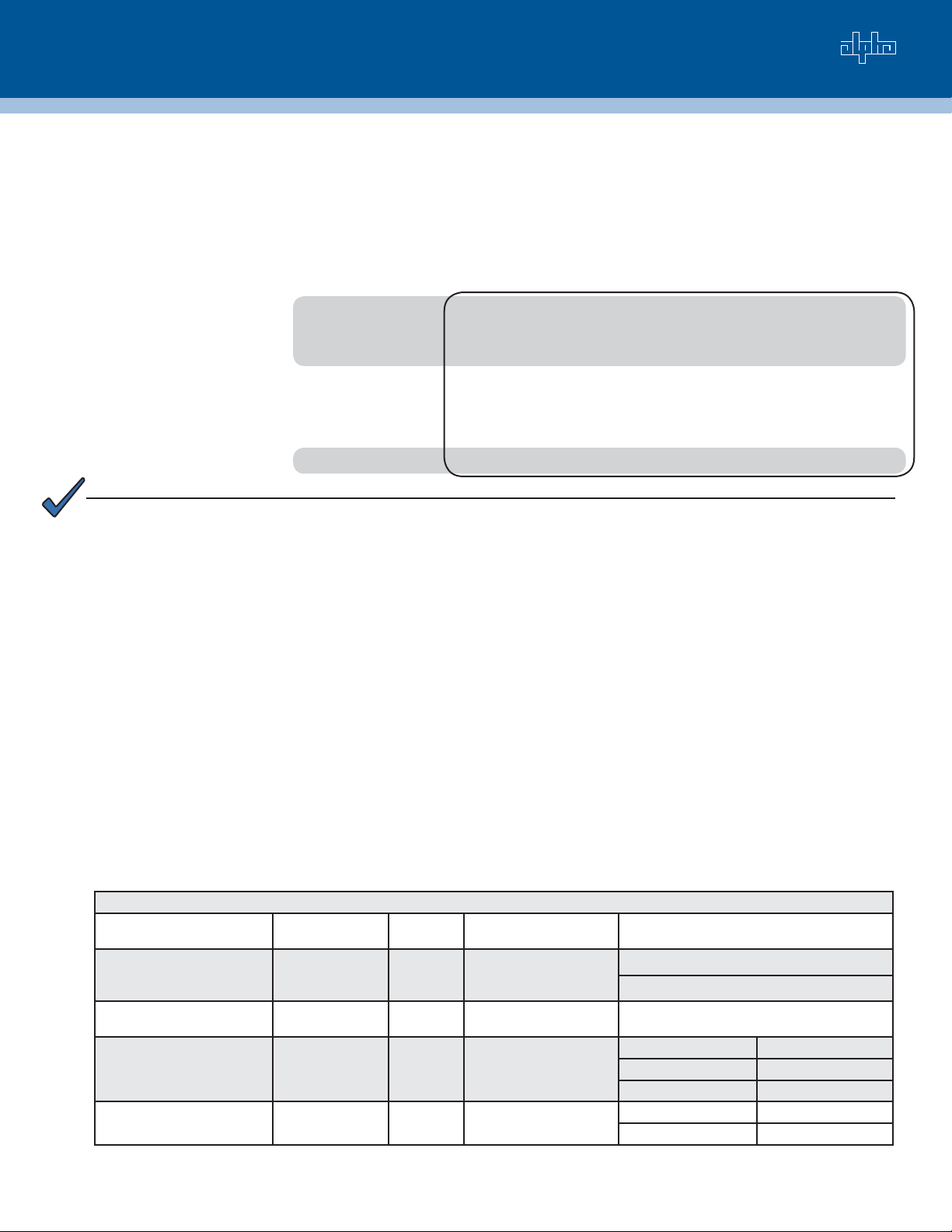
Transponder Communications Parameters
SNMP Parameter Local Port
atiCibDiscTable
1.3.6.1.4.1.926.1.2.1.1
atiMgmtSnmpTrapTable
OID: 1.3.6.1.4.1.926.1.3.1.1
atiMgmtSysHttpAccess
OID: 1.3.6.1.4.1.926.1.3.2.2.1
atiCibDiscTable
OID: 1.3.6.1.4.1.926.1.2.1.1
Parameter
[Discretes] TRAP
ON NORMAL
[Text] SNMP
TRAP T ARGET
[Discretes] HTTP
SERVER
[Discretes]
BLOCK CPE
Type Description Value
Integer Send SNMP trap when
alarmed condition returns
to normal state
IP Address SNMP Trap Table (up to
four entries)
Integer HTTP Web Server SNMP Local Port
Integer Access Mode(Single
IP/Dual IP)
0 = Disabled (default)
1 = Enabled
0.0.0.0 (default)
1 = Disable 1 = Enable (default)
2 = Enable (default) 0 = Disable
0 = Dual IP 0 = Dual IP
1 = Single IP (default) 1 = Single IP (default)
See the XP-DSM Technical Manual available at www.alpha.com for complete Alpha MIB parameter defi nitions.
page 1 of 2
Page 2
Total Power Solutions
Setting Options Locally
The local port allows a technician to monitor and set XP-DSM parameter values directly using a personal computer and
a Local Port Adapter Cable (Alpha P/N 745-826-21). Terminal emulation software is necessary (HyperTerminal is recommended). Serial communication settings are:
Baud: 19200 Data Bits: 8 Parity: None Stop Bits: 1 Flow Control: None
To change settings:
1. Launch the terminal emulation software
and hit ENTER to display the menu of
CIB tables.
2. Enter >[fi rst three letters of table] and
ENTER to display the contents of a table.
To disable the HTTP Server, which appears in the DISCRETE Table as:
SYS-1 10 HTTP SERVER 1 ENABLED YES
3. To set a parameter value, enter: >[table]
[subsystem] [Index] [Value], and hit
ENTER.
Enter: >dis sys 1 10 0 and hit ENTER. The result will be:
NOTE: Entries in the TEXT Table do not have
subsystems. Example: To set a SNMP Trap
Target to 10.20.30.40 Enter Command:
>tex 20 10.20.30.40 and hit ENTER.
SYS-1 10 HTTP SERVER 0 DISABLED YES
Setting Options with a DSM Setup File
An optional DSM Setup File, atidoc01.cfg, distributes settings automatically to XP-DSMs on a network. The XP-DSM is
programed to look for atidoc01.cfg at initialization and after every twenty-four hours of operation. If the fi le is not present
the XP-DSM will retain its settings. To build a DSM Setup File, enter SNMP parameters from the Alpha MIB and their
desired values inside a TLV fi le using a TLV editor. The entry atiMgmtSysDownloadCfgCheckProgress with the value
of 3 is the fi le marker that the XP-DSM looks for to begin reading entries and must be the fi rst entry in the fi le. Name the
fi le atidoc01.cfg and place it in the Root Directory of the TFTP Server specifi ed by the docsDevSwServer parameter in
the DOCSIS Confi guration File. See the XP-DSM Technical Manual for complete instructions on building a DSM Setup
File and for Alpha MIB parameter defi nitions.
Example Command
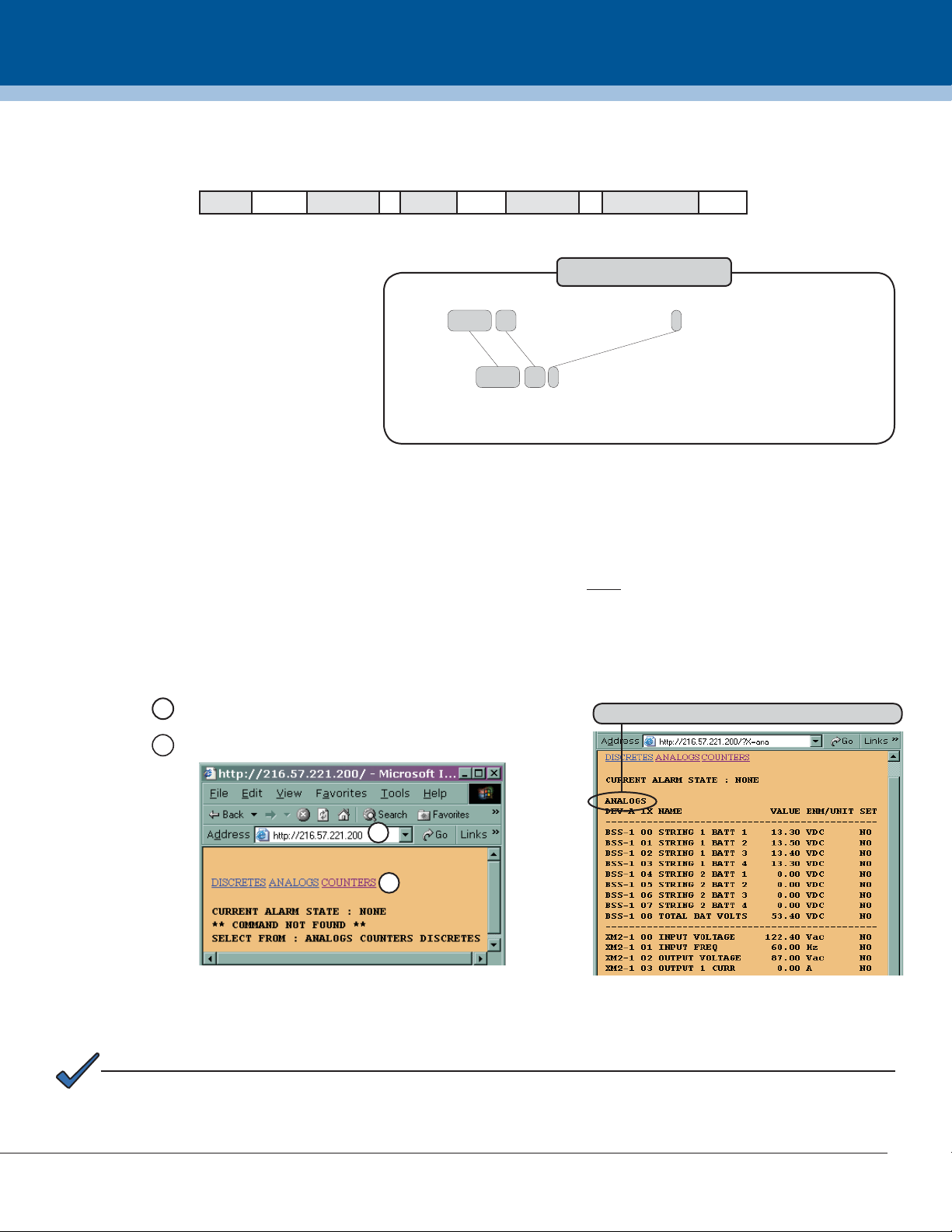
Step 6: Test the Connection
There are two methods to test whether a connection has been established:
Method One: Type the IP address of the transponder into a Web browser.
Click a link to see the associated power supply data.
1
Example of the Analogs power supply window
2
1
2
Method Two: To check connectivity and verify power supply data, the XP-DSM can be accessed with SNMP. Check
data within the psIdent MIB branch of the SCTE-HMS Tree by performing anzzz SNMP MIB walk to the SCTE-HMS-MIB
branch 1.3.6.1.4.1.5591.1. Verify that power supply data measurements are present.
NOTE:
See the XP-DSM Technical Manual available at www.alpha.com for extensive network confi guration and option
setting instructions, including MIB parameter defi nitions.
For more information visit www.alpha.com
United States Bellingham, Washington Tel: 360 647 2360 Fax: 360 671 4936
Canada Burnaby, British Columbia Tel: 604 430 1476 Fax: 604 430 8908
Alpha Technologies reserves the right to make changes to the products and information contained in this document without notice. To report errors in this document, email: techpubs@alpha.com
Copyright © 2007 Alpha Technologies. All Rights Reserved. Alpha® is a registered trademark of Alpha Technologies. member of The Alpha Group™ is a trademark of Alpha Technologies.
745-814-B1-002, Rev. B (12/2007)
page 2 of 2
 Loading...