

Page 1

Intelligent CableUPS
Technical Manual
XM3-HP Series
Effective: October 2013
®
Page 2

Alpha Technologies
Power
®
Page 3

Technical Manual
017-882-B0-001, Rev. C2
Effective Date: October 2013
Copyright 2013 Alpha Technologies, Inc.
NOTE:
Photographs contained in this manual are for illustrative purposes only. These photographs may not match your
installation.
NOTE:
Operator is cautioned to review the drawings and illustrations contained in this manual before proceeding. If there
are questions regarding the safe operation of this powering system, please contact Alpha Technologies or your
nearest Alpha representative.
NOTE:
Alpha shall not be held liable for any damage or injury involving its enclosures, power supplies, generators,
batteries or other hardware if used or operated in any manner or subject to any condition not consistent with its
intended purpose or is installed or operated in an unapproved manner or improperly maintained.
Notice of FCC Compliance
Per FCC 47 CFR 15.21:
Changes or modications not expressly approved by the party responsible for compliance could void the user’s authority to
operate the equipment.
Per FCC 47 CFR 15.105:
This equipment has been tested and found to comply with the limits for a Class A digital device, pursuant to part 15 of the
FCC Rules. These limits are designed to provide reasonable protection against harmful interference when the equipment
is operated in a commercial environment. This equipment generates, uses and can radiate radio frequency energy and, if
not installed and used in accordance with the instruction manual, may cause harmful interference to radio communications.
Operation of this equipment in a residential area is likely to cause harmful interference in which case the user will be required
to correct the interference at their own expense.
Contacting Alpha Technologies: www.alpha.com
or
For general product information and customer service (7 AM to 5 PM, Pacic Time), call
1-800-863-3930
For complete technical support, call
1-800-863-3364
7 AM to 5 PM, Pacic Time or 24/7 emergency support
Page 4

Table of Contents
Safety Notes ......................................................................................................................................................................................... 9
Safety Precautions ............................................................................................................................................................................... 9
Battery Safety Notes........................................................................................................................................................................... 10
Battery Maintenance Guidelines......................................................................................................................................................... 10
Utility Power Connection Notes ...........................................................................................................................................................11
Grounding and Earth Connection Notes............................................................................................................................................. 14
Safety Ground and Earth Connection ......................................................................................................................................... 14
Power Output Return................................................................................................................................................................... 14
Communications Grounding ........................................................................................................................................................ 15
1.0 Introduction.................................................................................................................................................................................. 16
1.1 Alpha XM3-HP Intelligent CableUPS® .................................................................................................................................. 16
1.2 Theory of Operation ............................................................................................................................................................. 17
1.2.1 AC (Line) Operation .................................................................................................................................................. 17
1.2.2 Standby Operation .................................................................................................................................................... 17
1.2.3 Charger Modes of Operation ..................................................................................................................................... 18
1.2.4 Output Voltage Modes of Operation .......................................................................................................................... 22
1.3 Alpha XM3-HP CableUPS® Layout ..................................................................................................................................... 23
1.3.1 Side Panel Connectors ............................................................................................................................................. 23
1.3.2 Front Panel Indicators ............................................................................................................................................... 24
1.3.3 AlphaDOC (PIM) ....................................................................................................................................................... 25
1.3.3.1 Installing the AlphaDOC ........................................................................................................................................ 26
1.3.3.2 Programming the AlphaDOC ................................................................................................................................ 27
1.3.4 Smart AlphaGuard ..................................................................................................................................................... 28
1.3.4.1 Theory of Operation .............................................................................................................................................. 28
1.3.4.2 Connections .......................................................................................................................................................... 29
Table of Contents
1.3.4.3 Alarms ................................................................................................................................................................... 31
1.3.4.4 LEDs ..................................................................................................................................................................... 32
1.3.4.5 Troubleshooting .................................................................................................................................................... 33
1.3.5 Inverter Module Overview ......................................................................................................................................... 34
1.3.6 Optional DOCSIS Status Monitoring Modules........................................................................................................... 35
2.0 Installation ................................................................................................................................................................................... 37
2.1 Installation Procedure .......................................................................................................................................................... 37
2.1.1 Pre-installation Inspection ......................................................................................................................................... 37
2.1.2 Internal Security Screw Kit Installation ...................................................................................................................... 37
2.2 XM3-HP Start-Up Procedure ................................................................................................................................................ 39
2.2.1 Parts and Connections .............................................................................................................................................. 39
2.2.2 Battery Installation Options and Wiring Diagram....................................................................................................... 40
2.2.2.1 Threaded Insert Terminals .................................................................................................................................... 41
2.2.3 120/240V Conguration Procedure ........................................................................................................................... 41
2.2.4 63/89VAC Output Voltage Reconguration Procedure .............................................................................................. 42
2.2.5 Optional AlphaDOC, Smart AlphaGuard, and Alpha APPS Installation ..................................................................... 43
2.2.6 Optional N+1 Congurations ..................................................................................................................................... 44
2.2.7 Communications DOCSIS Status Monitoring ............................................................................................................ 46
2.2.7.1 DOCSIS Status Monitor Front Panel Connections ............................................................................................... 46
2.2.7.2 LED Status Verication ......................................................................................................................................... 47
2.2.8 Power Module Conguration and Installation Procedure .......................................................................................... 48
4
017-882-B0-001 Rev. C2 (10/2013)
Page 5

Table of Contents
2.2.9 Local Verication of DOCSIS Transponder ............................................................................................................... 51
2.2.10 Web Interface ............................................................................................................................................................ 52
2.2.10.1 Local Web Server Access ................................................................................................................................... 52
2.2.11 Remote Web Server Access ..................................................................................................................................... 55
2.2.12 Navigating the Web Page .......................................................................................................................................... 56
2.2.12.1 Web Interface Security Levels ............................................................................................................................ 57
2.2.13 Verifying Communication Parameters ....................................................................................................................... 58
2.2.14 Verifying Power Supply and Battery Parameters ...................................................................................................... 59
2.2.15 Remote Self Tests via the Web Page ........................................................................................................................ 59
3.0 Operation..................................................................................................................................................................................... 60
3.1 Start-Up and Test ................................................................................................................................................................. 60
3.1.1 Self Test Operation .................................................................................................................................................... 60
3.2 Using the Smart Display....................................................................................................................................................... 61
3.3 Smart Display Menus ........................................................................................................................................................... 62
3.3.1 Power Information and Conguration ........................................................................................................................ 63
3.3.2 Battery Information and Conguration....................................................................................................................... 64
3.3.3 Communication Information and Conguration ......................................................................................................... 65
3.3.4 Alpha Applications Information and Conguration..................................................................................................... 68
3.4 AlphaAPPs Overview ........................................................................................................................................................... 69
3.4.1 Display Structure ....................................................................................................................................................... 69
3.4.2 Applications ............................................................................................................................................................... 71
3.5 Active Alarms ....................................................................................................................................................................... 80
3.5.1 Menu Structure/Navigation (from Active Alarms Screen) .......................................................................................... 81
3.5.2 PWR Alarms .............................................................................................................................................................. 82
3.5.3 BATT Alarms ............................................................................................................................................................. 83
3.5.4 COMM Alarms ........................................................................................................................................................... 84
3.5.5 APP Alarms ............................................................................................................................................................... 84
3.6 Smart Display Glossary ........................................................................................................................................................ 84
3.7 Automatic Performance Test ................................................................................................................................................ 88
3.8 Providing Power via Portable Generator or Inverter ............................................................................................................ 89
3.8.1 DC Powering ............................................................................................................................................................. 89
3.8.2 AC Powering ............................................................................................................................................................. 89
3.8.3 Using a Truck-mounted Inverter or Generator........................................................................................................... 90
3.9 Resumption of Utility Power ................................................................................................................................................. 91
Table of Contents
4.0 Maintenance ................................................................................................................................................................................ 92
4.1 Safety Precautions ............................................................................................................................................................... 92
4.2 Required Tools and Equipment ............................................................................................................................................ 92
4.3 Power Supply System Maintenance .................................................................................................................................... 93
4.3.1 Preparing for Maintenance ........................................................................................................................................ 93
4.3.2 Periodic Maintenance Tasks ......................................................................................................................................93
4.3.2.1 Remote Status Monitoring of Power Supply Self Test .......................................................................................... 93
4.3.2.2 On-Site Power Supply Preventive Maintenance ................................................................................................... 93
4.4 Battery Maintenance ............................................................................................................................................................ 96
4.4.1 Battery Notes............................................................................................................................................................. 96
4.4.2 Battery Maintenance Guidelines ............................................................................................................................... 97
4.4.3 Disposal, Recycling and Storage Instructions ........................................................................................................... 98
4.4.4 Capacity .................................................................................................................................................................... 99
4.4.5 Preparing for Maintenance ........................................................................................................................................ 99
017-882-B0-001 Rev. C2 (10/2013)
5
Page 6

Table of Contents
4.4.6 Periodic Maintenance Tasks ....................................................................................................................................100
4.4.6.1 Remote Status Monitoring .................................................................................................................................. 100
4.4.6.2 On-Site Battery Preventive Maintenance ............................................................................................................ 101
4.4.7 Battery Refurbishment Plan .................................................................................................................................... 104
4.4.8 Battery Evaluation Procedures for AlphaCell Batteries ........................................................................................... 105
4.5 XM3-HP System Preventive Maintenance Log .................................................................................................................. 106
5.0 Shut Down ................................................................................................................................................................................. 107
Appendix ........................................................................................................................................................................................ 108
Specications ............................................................................................................................................................................ 108
Safety and EMC Compliance .....................................................................................................................................................110
Simplied Block Diagram ...........................................................................................................................................................111
Battery Spacer Clips...................................................................................................................................................................112
System Options ..........................................................................................................................................................................113
Return and Repair Information ...................................................................................................................................................113
Figures
Fig. 1-1, Alpha XM3-HP Intelligent CableUPS ......................................................................................................................... 16
Fig. 1-2, 3-Stage Charger Modes............................................................................................................................................. 19
Fig. 1-3, 4-Stage Charger Modes............................................................................................................................................. 20
Fig. 1-4, 5-Stage Charger Modes............................................................................................................................................. 21
Fig. 1-5, Front Panel, XM3-HP Power Supply .......................................................................................................................... 23
Fig. 1-6, Side Panel, XM3-HP Power Supply ........................................................................................................................... 23
Fig. 1-7, Detail View, Front Panel Connections and Indicators ................................................................................................ 24
Table of Contents
Fig. 1-8, Output Voltage Terminal Block ................................................................................................................................... 26
Fig. 1-9, AlphaDOC Standoff and Screw Locations ................................................................................................................. 26
Fig. 1-10, 5-Position Output Voltage Terminal Block ............................................................................................................... 27
Fig. 1-11, Single Battery String Wiring Diagram (w/ embedded SAG Harness depicted) ........................................................ 29
Fig. 1-12, Multiple Battery String Wiring Diagram (w/ embedded SAG Harness depicted) ..................................................... 30
Fig. 1-13, SAG Front Panel ...................................................................................................................................................... 32
Fig. 1-14, Inverter Module Connections ................................................................................................................................... 34
Fig. 1-15, AlphaNet Series Communication Modules............................................................................................................... 36
Fig. 2-1, Required Materials ..................................................................................................................................................... 38
Fig. 2-2, Security Screw Mounting Location............................................................................................................................. 38
Fig. 2-3, Power Supply/Enclosure Shelf Security Screw Stack Up .......................................................................................... 38
Fig. 2-4, Installation of XM3-HP ............................................................................................................................................... 39
Fig. 2-5, Battery Wiring Diagram (w/ embedded SAG option depicted) ................................................................................... 40
Fig. 2-6, Precision Temperature Sensor (PTS), p/n 746-331-20 .............................................................................................. 40
Fig. 2-7, Battery Terminal Bolt Stack-up ................................................................................................................................... 41
Fig. 2-8, Fuse Bolt Stack-up..................................................................................................................................................... 41
Fig. 2-9, Transformer Harness ................................................................................................................................................. 41
Fig. 2-10, 120/240V Connector ................................................................................................................................................ 41
Fig. 2-11, Line Cord Plugs ........................................................................................................................................................ 42
Fig. 2-12, Input Voltage Setting Screen ................................................................................................................................... 42
6
017-882-B0-001 Rev. C2 (10/2013)
Page 7

Figures
Fig. 2-13, Removing Inverter Module and Output Voltage Terminal Location .......................................................................... 42
Fig. 2-14, Voltage Wire Position .............................................................................................................................................. 42
Fig. 2-15, Front Panel Fastener Locations .............................................................................................................................. 43
Fig. 2-16, APPS Card Standoff, Screw and Ribbon Cable Locations ..................................................................................... 43
Fig. 2-17, SAG Card Standoffs, Screws and Ribbon Cable Locations ................................................................................... 43
Fig. 2-18, SPI, AlphaDOC and SAG Harness Connections .................................................................................................... 44
Fig. 2-19, N+1 Conguration .................................................................................................................................................... 44
Fig. 2-20, Dual Redundancy N+1 Conguration ...................................................................................................................... 45
Fig. 2-21, Active Alarm Screen ................................................................................................................................................. 45
Fig. 2-22, N+1 In Use Alarm Screen ........................................................................................................................................ 45
Fig. 2-23, DOCSIS Status Monitor Front Panel Connections .................................................................................................. 46
Fig. 2-24, Active Alarm Table .................................................................................................................................................... 49
Fig. 2-25, Enter Battery Date Code .......................................................................................................................................... 49
Fig. 2-26, Enter Battery MHOs Reading .................................................................................................................................. 49
Fig. 2-27, Select Language in PWR CNFG Menu.................................................................................................................... 50
Fig. 2-28, COMM Menu Options .............................................................................................................................................. 51
Fig. 2-29, DSM3 Series Web Page .......................................................................................................................................... 52
Fig. 2-30, Local Area Connection Properties Screen, Windows XP ......................................................................................... 53
Fig. 2-31, Internet Protocol (TCP/IP) Properties Screen, Windows XP ................................................................................... 53
Fig. 2-32, Local Area Connection Properties Screen, Windows 7 ........................................................................................... 54
Fig. 2-33, Internet Protocol (TCP/IP) Properties Screen, Windows 7 ...................................................................................... 54
Fig. 2-34, Web Server Home Page .......................................................................................................................................... 55
Fig. 2-35, DSM3 Series Navigation Bar Items ......................................................................................................................... 56
Fig. 2-36, Communication Parameters .................................................................................................................................... 58
Fig. 2-37, Advanced Communication Parameters.................................................................................................................... 58
Fig. 2-38, Power Supply and Battery Parameters .................................................................................................................... 59
Fig. 2-39, Location of "Start" Button for Self Test ..................................................................................................................... 59
Fig. 3-1, Operation Normal Display Screen ............................................................................................................................. 61
Fig. 3-2, Navigating Through Menu Screens ........................................................................................................................... 61
Fig. 3-3, Input Voltage Settings Screen.................................................................................................................................... 62
Fig. 3-4, Active Alarm Table ...................................................................................................................................................... 80
Fig. 3-5, Sample Active Alarm Display, PWR Menu ................................................................................................................. 81
Fig. 3-6, Sample Active Alarm Display, BATT Menu................................................................................................................. 81
Fig. 3-7, Sample Active Alarm Display, COMM Menu .............................................................................................................. 81
Fig. 4-1, XM3-HP System Components ................................................................................................................................... 94
Fig. 4-2, Capacity vs. Storage Time for AlphaCell GXL ........................................................................................................... 98
Fig. 4-3, Capacity vs. Storage Time for AlphaCell HP .............................................................................................................. 98
Fig. 4-4, Available Capacity vs. Ambient Temperature ............................................................................................................. 99
Fig. 4-5, Flow Chart for Remote Status Monitoring .................................................................................................................. 100
Fig. 4-6, Flow Chart for Preventive Maintenance ..................................................................................................................... 101
Fig. 4-7, Flow Chart for Battery Refurbishment Plan ............................................................................................................... 104
Fig. 5-1, Emergency Shutdown ................................................................................................................................................ 107
Fig. A-1, Block Diagram ........................................................................................................................................................... 111
Fig. A-2, Placement of Battery Spacer Clips (for domestic and international 36V battery strings) .......................................... 112
Table of Contents
017-882-B0-001 Rev. C2 (10/2013)
7
Page 8

Tables
Table 1-1, Low Battery Cutoff (EOD) ........................................................................................................................................ 18
Table 1-2, Charger Modes of Operation ................................................................................................................................... 18
Table 1-3, Duration of Load ...................................................................................................................................................... 25
Table 1-4, Smart AlphaGuard LED Alarm States ..................................................................................................................... 32
Table 1-5, Comparative Features, AlphaNet Series Communications Modules ...................................................................... 36
Table 2-1, DSM3 LEDs Behavior ............................................................................................................................................. 47
Table 2-2, DSM3 Series Transponder Security Levels............................................................................................................. 57
Table 3-1, AC Output ................................................................................................................................................................ 60
Table 3-2, Main Menu Functions .............................................................................................................................................. 61
Table 3-3, Logged Events and Alarms ..................................................................................................................................... 72
Table 3-4, PWR Alarms: Classications, Causes and Corrections .......................................................................................... 82
Table 3-5, BATT Alarms: Classications, Causes and Corrections .......................................................................................... 83
Table 3-6, COMMs Alarms: Classications, Causes and Corrections...................................................................................... 84
Table 3-7, APP Alarms: Classications, Causes and Corrections ............................................................................................ 84
Table 4-1, On-Site Battery Preventive Maintenance ................................................................................................................ 103
Table 4-2, AlphaCell Conductance Values, Healthy vs. Suspect Batteries .............................................................................. 105
Table A-1, Product Certications Regarding Safety, EMC Compliance ................................................................................... 110
2.0 Installation
8
017-882-B0-001 Rev. C2 (10/2013)
Page 9

Safety Notes
Review the drawings and illustrations contained in this manual before proceeding. If there are any questions regarding
the safe installation or operation of the system, contact Alpha Technologies or the nearest Alpha representative. Save this
document for future reference.
To reduce the risk of injury or death and to ensure the continued safe operation of this product, the following symbols have
been placed throughout this manual. Where these symbols appear, use extra care and attention.
WARNING!
WARNING presents safety information to PREVENT INJURY OR DEATH to the technician or
user.
CAUTION!
The use of CAUTION indicates safety information intended to PREVENT DAMAGE to material or
equipment.
NOTE:
A NOTE provides additional information to help complete a specic task or procedure.
ATTENTION:
The use of ATTENTION indicates specic regulatory/code requirements that may affect the placement of equipment
and/or installation procedures.
Safety Precautions
• Only qualied personnel should service the Power Supply.
• Verify the voltage requirements of the equipment to be protected (load), the AC input voltage to the Power Supply
(line) and the output voltage of the system prior to installation.
• Equip the utility service panel with a properly rated circuit breaker for use with this Power Supply.
• When connecting the load, DO NOT exceed the output rating of the Power Supply.
• Always use proper lifting techniques whenever handling units, modules or batteries.
• The Power Supply contains more than one live circuit! Even though AC voltage is not present at the input, voltage
may still be present at the output.
• The battery string, which provides backup power, contains dangerous voltages. Only qualied personnel should
inspect or replace batteries.
• In the event of a short-circuit, batteries present a risk of electrical shock and burns from high current. Observe
proper safety precautions.
• Do not allow live battery wires to contact the enclosure chassis. Shorting battery wires can result in a re or
possible explosion.
• This Power Supply has been investigated by regulatory authorities for use in various Alpha enclosures. If you
are using a non-Alpha enclosure, it is your responsibility to ensure your combination conforms to your local
regulatory requirements and the Power Supply remains within its environmental specications.
9017-882-B0-001 Rev. C2 (10/2013)
Page 10

Battery Safety Notes
Any gelled or liquid emissions from a valve-regulated lead-acid (VRLA) battery contains diluted sulfuric acid, which is
harmful to the skin and eyes. Emissions are electrolytic and are electrically conductive and corrosive.
To avoid injury:
• Always wear eye protection, rubber gloves, and a protective vest when working near batteries. To avoid
battery contact, remove all metallic objects, (such as rings or watches), from your person.
• Batteries produce explosive gases. Keep all open ames and sparks away from batteries.
• Use tools with insulated handles, do not rest any tools on top of batteries.
• If any battery emission contacts the skin, wash immediately and thoroughly with water. Follow your company’s
approved chemical exposure procedures.
• Neutralize any spilled battery emission with the special solution contained in an approved spill kit or with
a solution of one pound bicarbonate of soda to one gallon of water. Report a chemical spill using your
company’s spill reporting structure and seek medical attention if necessary.
• Prior to handling the batteries, touch a grounded metal object to dissipate any static charge that may have
developed on your body.
• Use special caution when connecting or adjusting battery cabling. An improperly or unconnected battery cable
can make contact with an unintended surface that can result in arcing, re, or a possible explosion.
• A battery showing signs of cracking, leaking, or swelling should be replaced immediately by authorized
personnel using a battery of identical type and rating.
Battery Maintenance Guidelines
• During maintenance visits, inspect batteries for the following:
• Signsofbatterycracking,leakingorswelling. The battery should be replaced immediately by
authorized personnel using a battery of the identical type and rating.
• Signsofbatterycabledamage. Battery cable should be replaced immediately by authorized
personnel using replacement parts specied by vendor.
• Loosebatteryconnectionhardware. Refer to documentation for the correct torque and connection
hardware for the application.
• Always replace batteries with those of an identical type and rating. Match conductance, voltage and date codes.
• Do not attempt to remove the vents (valves) from the AlphaCell broadband battery or add water. This is a safety
hazard and voids the warranty.
• Apply NO-OX grease on all exposed connections.
• When necessary, clean up any spilled electrolyte in accordance with all federal, state, and local regulations or codes.
• Follow approved storage instructions.
• Always replace batteries with those of an identical type and rating. Never install untested batteries.
• Do not charge batteries in a sealed container. Each individual battery should have at least 1/2 inch of space between
it and all surrounding surfaces to allow for convection cooling.
• All battery compartments must have adequate ventilation to prevent an accumulation of potentially dangerous gas.
Never place batteries in a sealed enclosure. Extreme caution should be used when maintaining and collecting data on
the battery system. Ensure all enclosure vents and lters are clean and free of debris.
• Spent or damaged batteries are environmentally unsafe. Always recycle used batteries. Refer to local codes for
proper disposal of batteries.
10 017-882-B0-001 Rev. C2 (10/2013)
Page 11

Utility Power Connection Notes
NOTE:
Alpha enclosures are engineered to properly vent the Power Supply. The Power Supplies have been investigated by
regulatory authorities for use in various Alpha enclosures. If you are using a non-Alpha enclosure, it is your responsibility
to ensure your combination conforms to your local regulatory requirements and the Power Supply remains within its
environmental specications.
ATTENTION:
Connecting to the utility should be performed only by qualied service personnel and in compliance with local electrical
codes. Connection to utility power must be approved by the local utility before installing the Power Supply.
Local regulatory authorities may require the use of an approved service entrance and/or service disconnect switch when
the Power Supply is installed in an outdoor enclosure. Alpha enclosures have switch options. The installer may need to
provide these if using a non-Alpha enclosure.
NOTE:
In order to accommodate the high-inrush currents normally associated with the start-up of ferroresonant
transformers (400 Amp, no-trip, rst-half cycle), either a “high-magnetic” or an HACR (Heating, Air Conditioning,
Refrigeration) trip breaker must be used. Do not replace these breakers with a conventional service entrance
breaker. Alpha recommends ONLY Square D breakers because of the increased reliability required in this powering
application. High-magnetic Square D circuit breakers and a BBX option (UL Listed service entrance) are available
from Alpha Technologies.
Description Alpha Part Number Square D Part Number
240V Installation - HACR (15A) 470-224-10 QO215
120V Installation - High-magnetic (20A) 470-017-10 QO120HM
BBX - External Service Disconnect 020-085-10 QO2 -4L70RB
BBX - External Service Disconnect 020-141-10 QO8-16L100RB
ATTENTION:
In most cases, the following congurations qualify for service entrance use when wiring a duplex receptacle to a service
disconnect. Other codes may also apply. Always contact your local utility to verify the wiring conforms to applicable codes.
XM3-HP Connections
Proper 120VAC 20A service requires the installation site be:
• Equipped with a 120VAC duplex receptacle which provides power to the Power Supply and peripheral
equipment.
• Have a NEMA 5-20R receptacle protected by a single-pole, 20 Amp High Magnetic (HM) circuit breaker inside
the service entrance.
• Checked to NEC/CEC Code or with your local regulatory authority to verify proper wire AWG (suggested wire
gauge is 12AWG).
• Equipped with a grounding clamp on the enclosure to facilitate dedicated grounding.
NOTE:
When it is required to bond the box to a neutral plate, use the long green bonding screw provided (Alpha P/N
523-011-10, Square D P/N 40283-371-50).
11017-882-B0-001 Rev. C2 (10/2013)
Page 12
Utility Power Connection Notes, continued
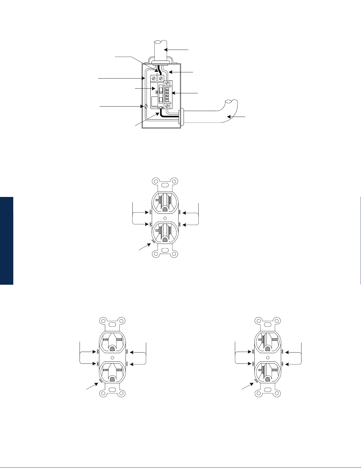
LI (Black)
To Utility
Copper Ground Wire
#8 AWG (Minimum)
Grounding Point Made
to Enclosure Wall
Neutral (White)
Breaker
Neutral Bus
LI (Black)
Typical 120VAC Service Entrance Wiring
Neutral
(White)
LI
(Black)
To Enclosure
Receptacle
Ground
(Green)
Typical 120 VAC 20A Receptacle Wiring, 5-20R
(P/N 531-006-19)
LI
(Black)
L2
(Red)
Ground
(Green)
Typical 240 VAC 20A Receptacle Wiring, 6-15R
(P/N 531-004-19)
LI
(Black)
L2
(Red)
Ground
(Green)
Typical 240 VAC 20A Receptacle Wiring, 6-20R
(P/N 531-008-19)
12 017-882-B0-001 Rev. C2 (10/2013)
Page 13
Utility Power Connection Notes, continued
Proper 240VAC 15A service requires the installation site be:
• Equipped with a 240VAC duplex receptacle to provide power to the Power Supply and peripheral equipment.
• Have a NEMA 6-15R receptacle that is protected by a single, 2-pole, common trip 15A circuit breaker inside
the service entrance.
• Checked to NEC/CEC Code or with your local regulatory authority to verify proper wire AWG (suggested wire
gauge is 14AWG).
• Equipped with a grounding clamp on the enclosure to facilitate dedicated grounding.
NOTE:
When it is required to bond the box to a neutral plate, use the long green bonding screw provided (Alpha P/N
523-011-10, Square D P/N 40283-371-50).
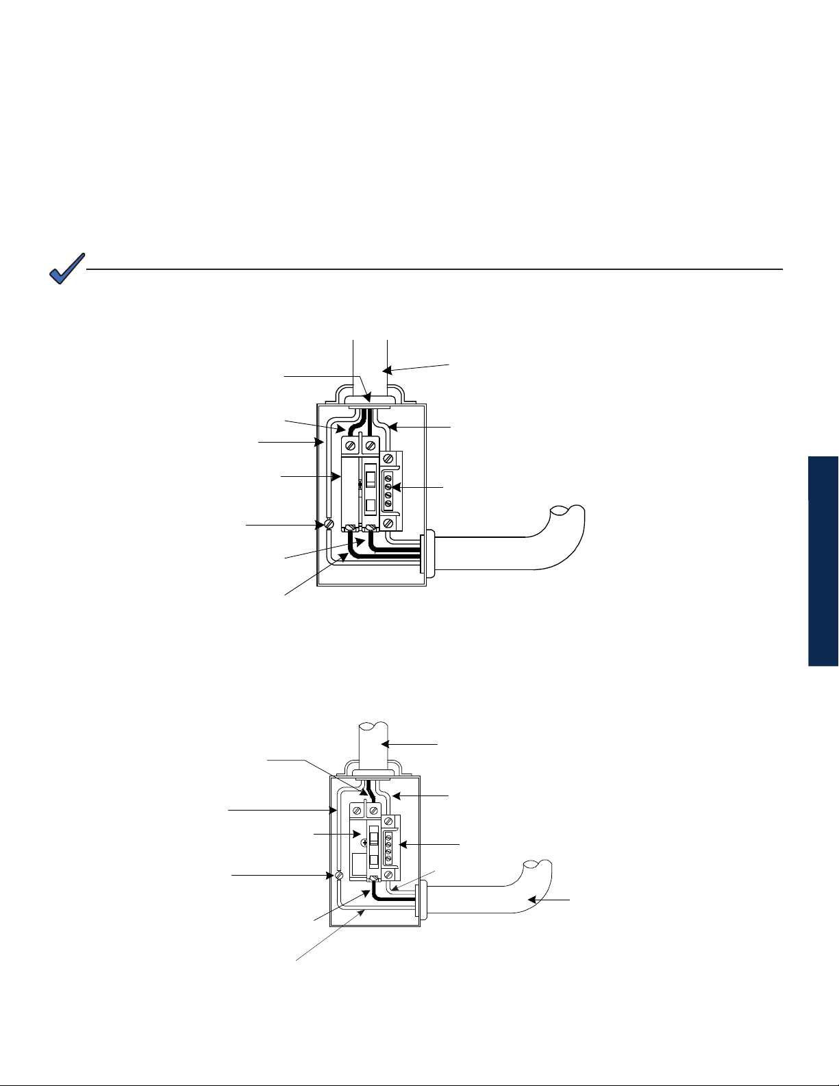
LI (Black)
L2 (Red)
Copper Ground Wire
#8 AWG (Minimum)
Breaker
Grounding Point Made
to Enclosure Wall
LI (Black)
L2 (Red)
LI (Brown)
To Utility
Neutral (White)
Neutral Bus
Typical 240VAC 60 Hz Service Entrance Wiring
To Utility
Copper Ground Wire
10mm2 or #8 AWG
(Minimum) (Yellow/Green)
Grounding Point Made
to Enclosure Wall
Copper Ground Wire
(Yellow/Green)
Neutral (Blue)
Breaker
Neutral Bus
Blue
LI (Brown)
Typical 230VAC 50Hz Service Entrance Wiring
To Enclosure
Receptacle
13017-882-B0-001 Rev. C2 (10/2013)
Page 14

Grounding and Earth Connection Notes
In order to provide a ready, reliable source of backup power, it is necessary to connect the Power Supply to an effective grounding
and Earthing system. This not only provides for the safety of the service personnel responsible for its operation and maintenance, but
also facilitates the proper operation and protection of the equipment within the network. Such a grounding system provides protection
with respect to operator safety, system communication and equipment protection.
Lightning strikes, grid switching or other aberrations on the power line and/or communications cable have the potential to cause highenergy transients that can damage the powering or communications systems. The most viable method available to protect the system
from damage is to divert these unwanted high-energy transients along a low-impedance path to earth. A low-impedance path to earth
prevents these currents from reaching high voltage levels and posing a threat to equipment.
The key to the success of lightning protection is single-point grounding so the components of the grounding system appear as a
single point of uniform impedance. Two places recommended by Alpha for single-point grounding are connections in the enclosure
and connections to earth. Single-point grounding in the enclosure is achieved by bonding all electrical connections to the enclosure,
including the connection to earth, as close together on the enclosure as possible. Single-point grounding for the connection to earth
is achieved, for example by the proper bonding of the ground rods.
Safety Ground and Earth Connection
The safety ground and earth is a two-part system, comprised of the utility service and the Alpha system.
1. The utility service;
As a minimum requirement for the protection of Alpha equipment, the local utility service must provide a low-
impedance path for fault current return. In addition, there must be a low impedance bonded path between the
Power Supply ground pin and the enclosure.
2. The Alpha grounding system;
The Alpha grounding system consists of a low-impedance connection between the enclosure and an Earth
Ground (located at least 6’ away from the Utility Earth connection).
This impedance between the enclosure and Earth must be 25 Ohms or less at 60 Hertz as measured by AMPROBE
Model DGC-1000 or equivalent. The measurement should be made on the wire or ground rod after it exits the
enclosure.
Local soil conditions will determine the complexity of the grounding system required to meet the 25 Ohm (maximum)
resistance specied above. For example, a single 8’ ground rod may be sufcient to meet the requirement. In
some cases, a more elaborate system may be required such as multiple ground rods connected by a #6AWG
solid copper cable buried 8-12” below the surface. Where this is not possible, contact a local grounding system
expert for alternate methods that will meet the 25 Ohm (maximum) specication.
All ground rod connections must be made by means of a listed grounding clamp suitable for direct burial or
exothermic welding.
Power Output Return
For proper operation, the Service Power Inserter (SPI) must be securely bonded to the enclosure.
SPI
14 017-882-B0-001 Rev. C2 (10/2013)
Page 15
Grounding and Earth Connection Notes, continued
Communications Grounding
For systems using an embedded transponder, the grounding connection is typically made either through a separate chassis ground
block bonded to the enclosure or by means of the internal mounting hardware which bonds the transponder through the CableUPS.
Please refer to the appropriate communications product manual for installation procedures.
For communication cables, Alpha strongly recommends the use of a surge arresting device electrically bonded to the Alpha Enclosure.
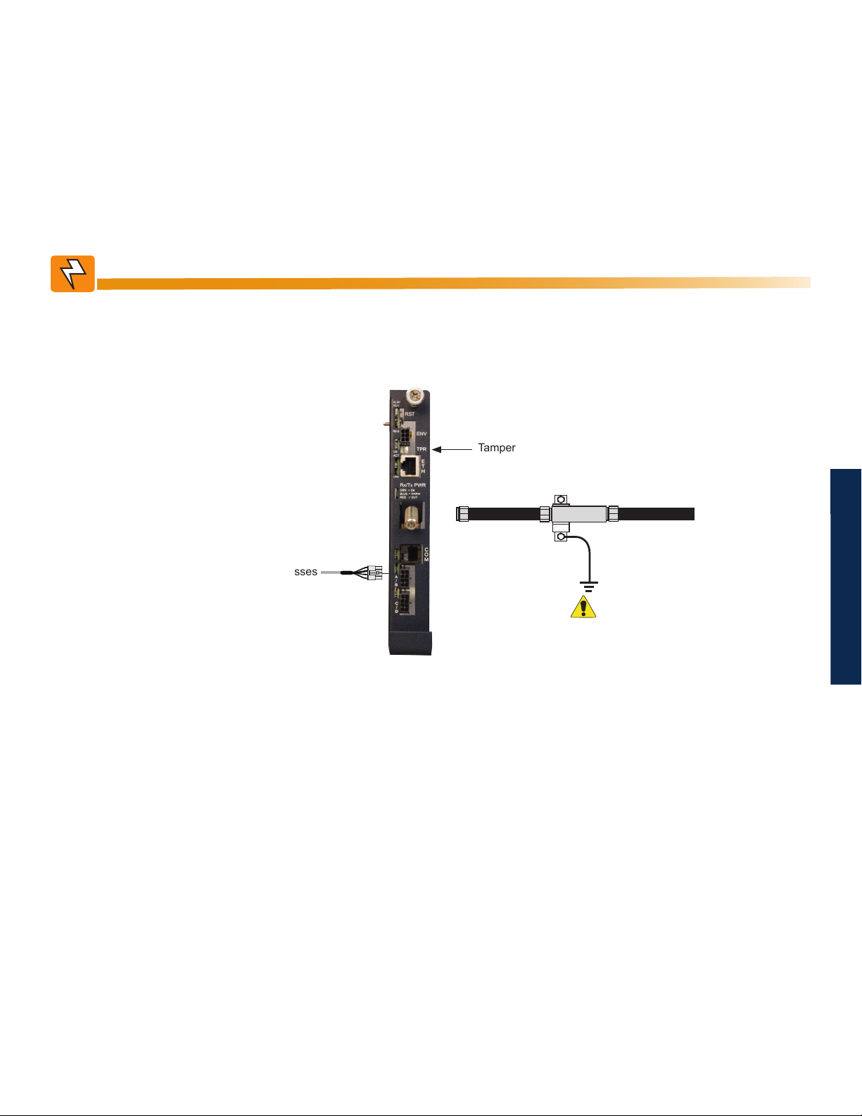
WARNING!
Low impedance grounding is mandatory for personnel safety and critical for the proper
operation of the cable system.
Tamper Switch Connector
To Battery Sense Wire Harnesses
RF Cable to Headend
Required
Grounded Surge Protector
(Alpha p/n 162-028-10 or equivalent)
15017-882-B0-001 Rev. C2 (10/2013)
Page 16
1.0 Introduction
1.0 Introduction
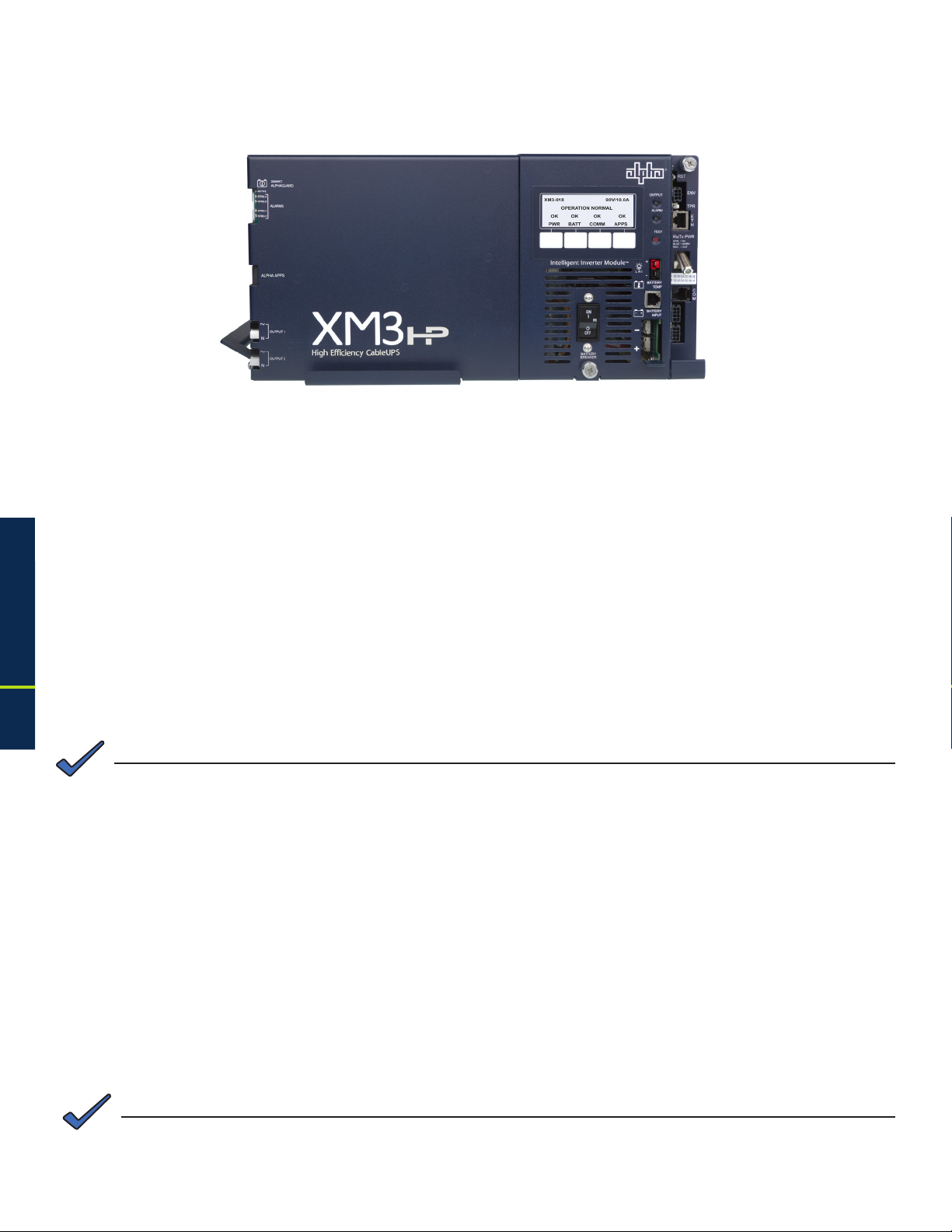
1.1 Alpha XM3-HP Intelligent CableUPS
Fig. 1-1, Alpha XM3-HP Intelligent CableUPS
The Intelligent CableUPS® powers signal processing equipment in cable television and broadband LAN
distribution systems. The transformer module provides a critical load with current-limited regulated AC power
that is free of spikes, surges, sags and noise.
During AC line operation, AC power entering the Power Supply is converted into a quasi square wave and is
regulated by a ferroresonant transformer at the required output voltage. The regulated voltage is connected
to the load via the output connectors and some power is directed to the battery charger to maintain a oat
charge on the batteries.
When the incoming AC line voltage signicantly deviates from normal, the Inverter Module automatically
switches to standby operation and maintains power to the load. During the switch to standby operation,
energy in the module’s ferroresonant transformer continues to supply power to the load. In standby mode,
the Power Supply powers the load until the battery voltage reaches a low-battery cutoff point.
When utility power returns, the transformer module waits a short time (approximately 10 to 20 seconds) for the
utility voltage and frequency to stabilize and then initiates a smooth, in phase transfer back to AC line power.
Once the transfer is complete, the battery charger recharges the batteries in preparation for the next event.
NOTE:
®
16
The duration of battery-backed standby operation depends upon the type and number of batteries and the load on
the Power Supply.
The Alpha XM3-HP CableUPS contains the following:
• Smart Display
• Hot-swappable Inverter Module
• Built-in Self Test
• Wide Input voltage range
• High efciency transformer
• Communications menu with DOCSIS®
parameters (only with optional DSM3 or IDH4
installed)
• Optional factory-installed AlphaDOC (PIM)
allows the XM3-HP to provide programmable
current limits for two output channels.
NOTE:
During a no-load start-up, the Power Supply may reduce output voltage to 75-80% of rated output voltage until a
load of greater than 1.5A is applied.
• Optional Smart AlphaGuard (SAG)
• Optional AlphaAPPs (APPS) card
• Via the Smart Display, the operator can
view all of the Power Supply’s operating
parameters.
• Troubleshooting tips automatically display
in the Alarm menu screen.
• Built-in metering circuits measure voltage
and current, without the need for external
test equipment.
017-882-B0-001 Rev. C2 (10/2013)
Page 17

1.0 Introduction, continued
1.2 Theory of Operation
1.2.1 AC (Line) Operation
During AC Line operation, utility power is routed into the primary winding of the ferroresonant
transformer through the contacts of the transfer isolation relay. Simultaneously, in the inverter, power
is directed to the rectier circuitry providing power for the control circuitry. The bidirectional inverter
also serves as a battery charger during line operation. The ferroresonant transformer and an AC
capacitor form the resonant tank circuit, which provides excellent noise and spike attenuation, output
short-circuit current-limiting, and output voltage regulation. The ferroresonant transformer produces
a quasi square wave output which resembles a rounded square wave.
NOTE:
When measuring the output voltage of ferroresonant transformers, use only a true RMS AC voltmeter. NonRMS reading meters are calibrated to respond to pure sine waves and do not provide an accurate reading when
measuring quasi square wave output.
1.2.2 Standby Operation
When the incoming AC line voltage drops or rises signicantly or a complete power outage occurs,
the control logic’s line monitor activates standby operation. During the transfer from AC line to standby
operation, the battery powered inverter comes online as the isolation relay switches to prevent AC
power from back-feeding to the utility. The following changes also occur within the Power Supply:
• The isolation relay opens to disconnect the AC line from the primary winding of the ferroresonant
transformer.
• The control logic switches the inverter FETs on and off. This switching action converts the DC
battery current into AC current in the inverter windings of the ferroresonant transformer, providing
regulated power to the load.
• The control logic, which includes a microprocessor and other circuits to protect the inverter
FETs from overcurrent damage, monitors the condition of the batteries and the inverter during
standby operation. Since a prolonged AC line outage could severely discharge the batteries,
resulting in permanent damage, the control logic disables the inverter when the batteries drop
to a predetermined cutoff voltage.
• The XM3-HP offers two user-selectable EOD options based on either overall string voltage or
individual battery voltage. See Table 1-1 for battery specic EOD settings. Operation is dened
as follows:
• Battery String Voltage Mode which shuts off the inverter when the 36V bus voltage reaches
Low Battery Cutoff Voltage as seen at the inverter.
• Individual Battery Voltage Mode which shuts off the inverter when any battery in any string
(1-4) reaches Low Battery Cutoff Voltage.
• All units will factory default to Battery String Voltage Mode.
• Individual battery EOD will only be available (user-selectable) if individual battery voltages
are being sensed and present at logic card via the Smart AlphaGuard, DSM3 or other
approved status monitor card with individual battery voltage sensing.
1.0 Introduction
• When set to Battery String Voltage Mode the “Low Battery Cutoff” (EOD) is not user adjustable
from the default. See Table 1-1 for more information.
• When set to individual Battery Voltage Mode the “Low Battery Cutoff” (EOD) will automatically
set to default values based on battery type (see Table 1-1). A secondary option is then
offered to the user for manually programming the “Low Battery Cutoff” (EOD), regardless
of battery type, within the range 1.65 to 1.80 V/C.
17017-882-B0-001 Rev. C2 (10/2013)
Page 18

1.0 Introduction, continued
1.2 Theory of Operation, continued
1.2.2 Standby Operation, continued
• When set to Individual Battery Voltage Mode, if individual battery voltage is lost, the unit automatically
reverts back to Battery String Voltage Mode and "Low Battery Cutoff” (EOD) will revert back to default
value based on battery type.
String Low Battery
Cutoff (EOD)
Individual Low
Battery Cutoff
HP Batteries
OTHER Batteries
(EOD)
HP Batteries GXL Batteries OTHER Batteries
Fixed Fixed Fixed
30.6 VDC
(1.70 V/C)
Default Minimum Maximum
10.2 VDC
(1.70 V/C)
10.5 VDC
(1.75 V/C)
10.5 VDC
(1.75 V/C)
31.5 VDC
(1.75 V/C)
9.9 VDC
(1.65 V/C)
31.5 VDC
(1.75 V/C)
10.8 VDC
(1.80 V/C)GXL Batteries
Table 1-1, Low Battery Cutoff (EOD)
1.0 Introduction
• When acceptable AC line voltage returns, the Power Supply returns to AC line operation after a 10
to 20 second lag. This delay lets the AC line voltage and frequency stabilize before the control logic
phase-locks the inverter’s output to the utility input. The control logic then de-energizes the isolation
relay, reconnects the AC line to the primary of the ferroresonant transformer and disables (turns off)
the inverter. This results in a smooth, in-phase transfer back to utility power without interruption of
service to the load. The battery charging circuit then activates to recharge the batteries in preparation
for the next power outage.
1.2.3 Charger Modes of Operation
AlphaCell Batteries OTHER Batteries
HP GXL Default Minimum Maximum
Float V/C 2.25 2.27 2.27 2.10 2.35
Accept V/C 2.35 2.40 2.40 2.20 2.45
Automatic 30-Minute
Refresh On/Off
Manual 24-Hour
Refresh On/Off
Refresh V/C 2.45 2.45 2.45 2.40 2.50
Rest On/Off ON OFF
Temperature
Compensation
ON ON OFF OFF OFF
OFF
(Programmable)
-4mV / ºC / cell - 5mV / ºC / cell
OFF
(Programmable)
OFF
(Programmable)
OFF
(Programmable)
-5mV / ºC / cell
(Programmable)
OFF ON
OFF ON
0 mV / ºC / cell -5mV / ºC / cell
18
Table 1-2, Charger Modes of Operation
NOTE:
If a battery type other than an AlphaCell is installed, it is the responsibility of the technician to review the proper
charging specications for the battery used.
017-882-B0-001 Rev. C2 (10/2013)
Page 19

1.0 Introduction, continued
1.2 Theory of Operation, continued
1.2.3 Charger Modes of Operation, continued
The Alpha XM3-HP uses a three-stage (other), four-stage (AlphaCell GXL), or ve-stage
(AlphaCell HP) temperature compensated battery charger as determined by the type of
battery used in the system. During AC line operation, the inverter winding on the ferroresonant
transformer feeds the charger circuit which provides the appropriate charge voltages to the
batteries.
3-Stage Charger Modes (BULK/ACCEPT/FLOAT):
The 3-stage charger is applied when the battery type of OTHER is selected in the Smart Display
menu.
BULK charge is a “Constant Current” charge. The maximum current is 10A. As the charge is
returned to the batteries, their voltage increases to a specic threshold (2.40VDC per cell). The
charger then switches to ACCEPT mode. The BULK charger mode generally returns the battery
charge state to 80 percent of rated battery capacity.
ACCEPT charge is a “Constant Voltage” charge. This voltage, default 2.40VDC (programmable
2.20-2.45VDC) per cell, is temperature-compensated to ensure longer battery life and proper
completion of the charge cycle. This cycle is complete when the charging current into the
batteries becomes less than 0.5A or approximately six hours elapses from the time ACCEPT
mode was entered, at which time the charger switches to the FLOAT mode of operation.
FLOAT charge is a temperature-compensated charge, default 2.27VDC (programmable 2.10-
2.35VDC) per cell. During FLOAT mode, the batteries are fully charged and ready to provide
backup power. The charger provides a small maintenance charge to overcome the batteries selfdischarge characteristics and other minor DC loads within the Power Supply.
Battery Voltage
Battery Current
1.0 Introduction
BULK
Constant
Current Mode
(10A max) until
battery voltage
reaches the
ACCEPT level
(2.40V/cell)
Fig. 1-2, 3-Stage Charger Modes
ACCEPT
Constant Voltage Mode
(2.40V/cell) until battery
current demand drops
below .5A or time out
based on 4 minutes per
Ah battery capacity
FLOAT
Constant
Voltage Mode
(2.27V/cell)
19017-882-B0-001 Rev. C2 (10/2013)
Page 20

1.0 Introduction, continued
1.2 Theory of Operation, continued
1.2.3 Charger Modes of Operation, continued
4-Stage Battery Charger (BULK/ACCEPT/REFRESH/FLOAT):
This preset value is applied to AlphaCell GXL batteries when selected in the Smart Display Menu.
A 30-minute REFRESH charge is added, after BULK and ACCEPT states, before dropping down
to FLOAT state, when the batteries are discharged more than 30% and it has been more than 30
days since the last REFRESH charge.
A manual REFRESH charge mode is recommended to be applied to all new batteries upon
installation. This mode “boosts” the individual cell voltage of batteries that may have been in
storage before they were placed on permanent FLOAT. Refresh can be initiated manually via
menu selection or automatically when the battery date code is updated (See Section 3.3.2,
Battery Information and Conguration for further instructions). The REFRESH charge is a one-
time, 24-hour charge to raise individual cell voltage to 2.45VDC, and may bypass the BULK and
ACCEPT states if the batteries are fully charged. The batteries are temperature-compensated at
-0.005VDC per cell per degree C to ensure safe battery cell voltage and maximize battery life.
Battery Voltage
1.0 Introduction
Battery Current
BULK
Constant
Current Mode
(10A max) until
battery voltage
reaches the
ACCEPT level
(2.40V/cell)
ACCEPT
Constant Voltage Mode
(2.40V/cell) until battery
current demand drops
below .5A or time out
based on 4 minutes per
Ah battery capacity
REFRESH
Constant
Voltage Mode
(2.45V/cell)
for 30 minutes
Fig. 1-3, 4-Stage Charger Modes
FLOAT
Constant
Voltage
Mode
(2.27V/cell)
20
017-882-B0-001 Rev. C2 (10/2013)
Page 21
1.0 Introduction, continued
1.2 Theory of Operation, continued
1.2.3 Charger Modes of Operation, continued
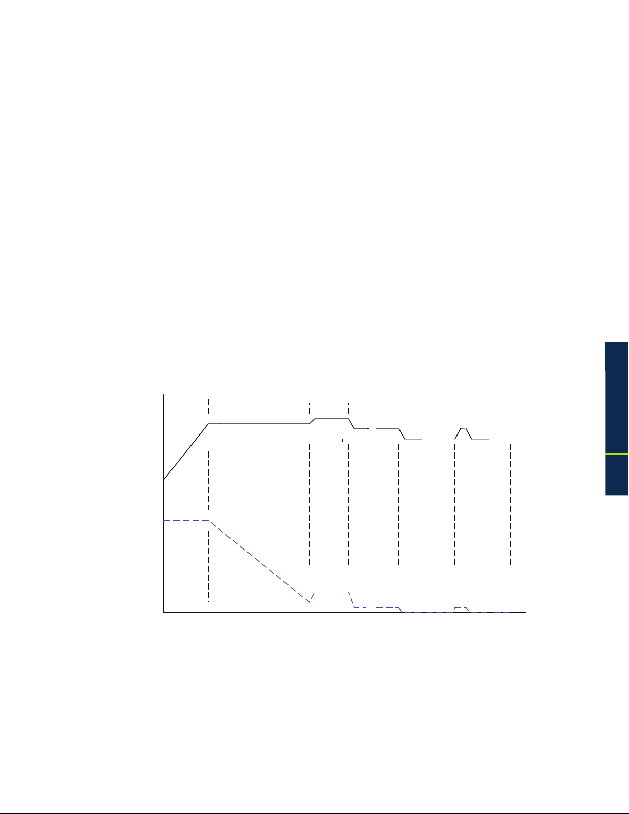
5-Stage Battery Charger (BULK/ACCEPT/REFRESH/FLOAT/REST):
This preset value is applied to AlphaCell HP batteries when selected in the Smart Display Menu.
REST: Charger is turned off (if ENABLED) and leaves the batteries without external voltage
applied on the battery. Removing charged voltage and allowing the battery to sit in an open
circuit environment maximizes the battery life by eliminating the chance of overcharging individual
cells inside the 12V battery.
If the Smart AlphaGuard (SAG) is installed and the battery harness is connected, the unit will not
go into REST mode until the SAG indicates that any batteries are less than or equal to 0.3V out of
balance, or until 4 days per string has elapsed, whichever comes rst after the 6 hour oat period.
After any discharge/recharge cycle, once the charger reaches FLOAT mode, it will wait 24 hours
in FLOAT mode before going to REST mode. On a daily basis, without any discharge cycle, the
batteries will be in FLOAT for 25% and REST (charger off) for 75% (6 hours oat, 18 hours rest).
REST mode is terminated if voltage drops to less than 2.12VPC. Upon exiting REST mode due
to a voltage below 2.12VDC, a BULK/ACCEPT cycle will be initiated.
The battery charger voltage is temperature-compensated at -0.004VDC per cell per degree C to
ensure a safe battery cell voltage and to maximize battery life.
BULK
Constant
Current Mode
(10A max) until
battery voltage
reaches the
ACCEPT level
(2.40V/cell)
Battery Voltage
Battery Current
ACCEPT
Constant Voltage
Mode (2.40V/cell)
until battery current
demand drops below
.5A or time out based
on 4 minutes per Ah
battery capacity
Fig. 1-4, 5-Stage Charger Modes
REFRESH
Constant
Voltage
Mode
(2.45V/cell)
for 30
minutes
FLOAT
Constant
Voltage
Mode
(2.27V/cell)
Initial 24
hours
REST
Charger Off
Open Circuit
Voltage
18 hours
1.0 Introduction
FLOAT
AND REST
CYCLES
Charger off for
18 hours
Float for 6
hours
21017-882-B0-001 Rev. C2 (10/2013)
Page 22

1.0 Introduction, continued
1.2 Theory of Operation, continued
1.2.4 Output Voltage Modes of Operation
The XM3-HP can be congured to Fine or Coarse Mode of operation for Output Voltage
Regulation via the Power Conguration Menu (see Section 3.3.1, Power Information and
Conguration).
Fine Mode:
In Fine Mode the power supply will maintain the tightest output voltage regulation possible,
+1/-2.5% for 89V or +1.5/-3.5% for 63V. It will automatically adjust to and from Coarse Override
Mode temporarily if:
a) The unit switches to inverter more than 2 times in a 60-day period;
b) the unit switches tap relays more than 60 times in a 60-day period.
The power supply will automatically adjust back to Fine Mode if there are less than 2 inverter
transfers and less than 15 output tap switches in a 60-day period.
Coarse Mode:
In Coarse Mode the XM3-HP will maintain a wider output voltage regulation window, +1/-5% for
89V or +1.5/-6% for 63V. In this mode the power supply switches taps as few times as possible. It
will never automatically adjust to Fine Mode once Coarse Mode is selected.
1.0 Introduction
22
017-882-B0-001 Rev. C2 (10/2013)
Page 23

1.0 Introduction, continued
1.3 Alpha XM3-HP CableUPS® Layout
The Intelligent CableUPS is comprised of the following:
Transformer module, which acts as a stand-alone line conditioner. The transformer module contains a
ferroresonant transformer, ferroresonant capacitor, line isolation relay, Power Distribution Board, EMC
Filter board and the optional AlphaDOC (PIM) board, Smart AlphaGuard (SAG) and Alpha APPS card.
NOTE:
The option cards require an Inverter Module installed in order to be functional.
Intelligent Inverter Module, which is required for standby operations and contains circuitry needed for
the three-to-ve-stage temperature-compensated battery charger, DC to AC inverter, AC line detectors
and Smart Display.
Optional DOCSIS Communications Module (interfaces to Inverter Module) provides remote status
monitoring and communications.
High Efciency
Transformer Module
Intelligent Inverter
Module
DOCSIS
Communications
Module
®
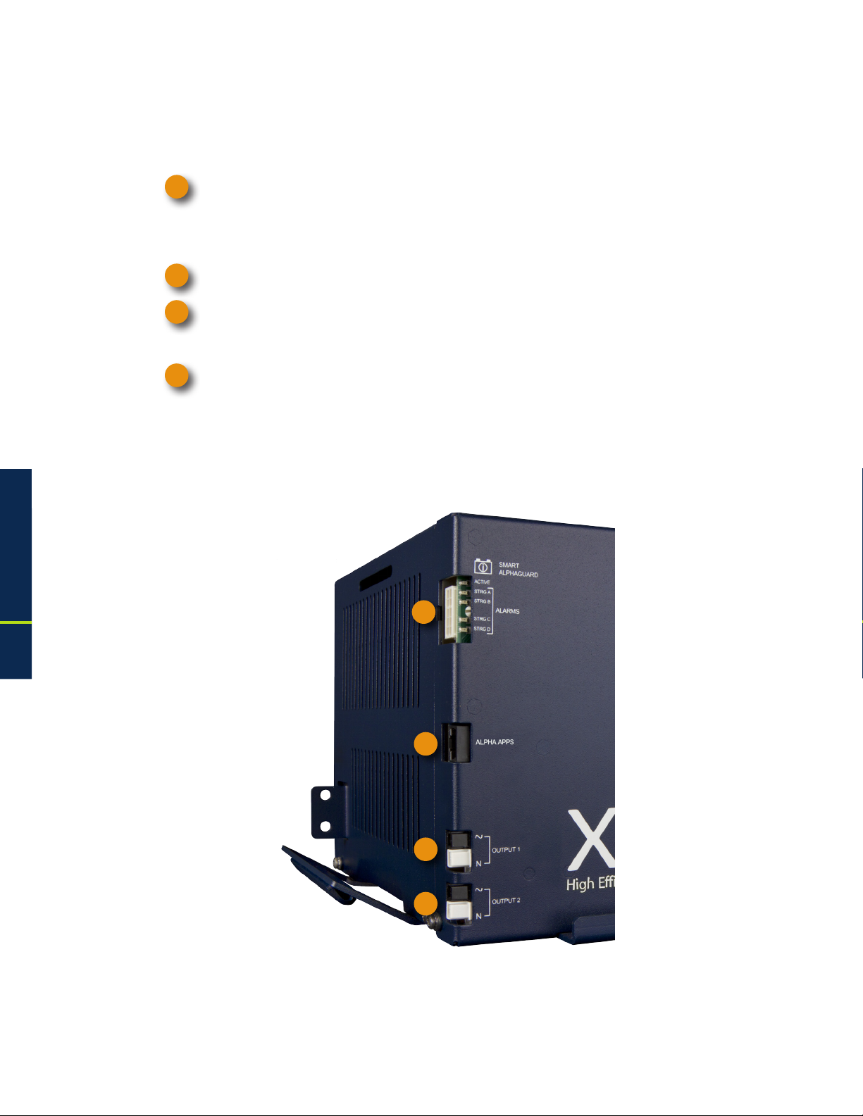
1.3.1 Side Panel Connectors
1
AC Input Line Cord Connector
Optional Smart AlphaGuard Connector
2
3
Optional APPS Card
4
Output 1 Connector
5
Output 2 Connector
Fig. 1-5, Front Panel, XM3-HP Power Supply
1
Fig. 1-6, Side Panel, XM3-HP Power Supply
1.0 Introduction
2
3
4
5
23017-882-B0-001 Rev. C2 (10/2013)
Page 24
1.0 Introduction, continued
1.3 Alpha XM3-HP CableUPS Layout, continued
1.3.2 Front Panel Indicators
Circuit boards for the optional Smart AlphaGuard (SAG), Alpha APPS card and the two-output
AlphaDOC (PIM) are located behind the removable front panel.
1
Smart AlphaGuard (SAG): Enables the XM3 to gather battery voltage data for up four battery
strings (A through D). Its Charge Management Technology applies excess charge current to
batteries as needed to maintain balanced voltages throughout the string. See Section 1.3.4,
Smart AlphaGuard for connection information and LED functionality.
Alpha APPS Card
2
Output 1 (White = Neutral, Black = Line): The AC output connector is clearly marked and color-
3
coded for easy identication. The Service Power Inserter (SPI) connects directly into the Output 1
connector.
4
Output 2 (White = Neutral, Black = Line): When no AlphaDOC is installed, this output is wired in
parallel to Output 1 and is often used for auxiliary loads. If the AlphaDOC is installed, Output 2
can be isolated from Output 1.
1.0 Introduction
1
2
3
4
Fig. 1-7, Detail View, Front Panel Connections and
Indicators
24
017-882-B0-001 Rev. C2 (10/2013)
Page 25

1.0 Introduction, continued
1.3 Alpha XM3-HP CableUPS Layout, continued
1.3.3 AlphaDOC (PIM)
The optional AlphaDOC adds a second isolated output to the Power Supply. It provides programmable
current limits for two output channels and protects system components by shutting down the load
during overcurrent and short circuit conditions.
The AlphaDOC has a programmable overcurrent threshold (3A-25A) and overcurrent tolerance period
that species the time (20-9900ms) an overcurrent condition is permitted before shutting down.
The programmable retry limit can be programmed to select how many times (0-40) after a
programmable delay (5-301 seconds) the AlphaDOC will attempt to reconnect an output once it
has been shut down. When the limit is reached, the XM3 Power Supply automatically retries once
every 30 minutes until the fault clears.
Adding the AlphaDOC to the Power Supply provides these advantages:
A second isolated output: The main purpose of the AlphaDOC is to limit the impact of a
fault condition in one output channel. If a fault condition occurs in a Power Supply (without
the optional AlphaDOC installed) the entire customer network can be affected. The AlphaDOC
option affords protection to one output should a fault condition exist on the other. This gives
you exibility to isolate Output 1 from Output 2.
A current for critical loads: With the AlphaDOC option, you can designate one output
as the primary connection and the other output as the secondary connection. Commonly,
critical loads are connected to Output 1 as the primary feeder. Using the overcurrent limit
settings, you can ensure the primary output always provides the necessary power. For
example, on a 15 Amp Power Supply, if a customer needs 10 Amps available on Output 1,
the overcurrent limit for Output 2 is set at 5 Amps, so regardless of Output 2, 10 Amps will
remain available for the primary Output 1.
Additional current protection: The standard Power Supply current limit protection is
provided by the fold-back characteristics of the transformer (150% of rated output). The
150% current limit may exceed the ratings of active devices in the cable network and
cause failures. You can lower the maximum current provided at each output by lowering the
overcurrent limit of each respective output. Therefore, to minimize failures due to excess
current supply, set the overcurrent limit to a value below the maximum current the active
components can tolerate.
NOTE:
The table below depicts a condition in which no DOC is installed, or no individual output is above
its trip setting.
Power Supply Load
918
All Other Models
Permitted Duration of Load
>125% >150% 30 seconds
113% to 125% 125% to 150% 10 minutes
108% to 113% 115% to 125% 30 minutes
<108% <115% Several months
Table 1-3, Duration of Load
For example, on a 18A Power Supply, where both outputs are programmed to 10A maximum
and both outputs are supplying 10A, neither output is “in violation” but the total system at 18A
is operating at 111% of its rated output. In this example, after 30 minutes, the Power Supply
will begin a “load shedding” algorithm. The rst action is to disconnect Output 2. If this does not
correct the system overload, the next action is to disconnect Output 1.
1.0 Introduction
25017-882-B0-001 Rev. C2 (10/2013)
Page 26

1.0 Introduction, continued
1.3 Alpha XM3-HP CableUPS Layout, continued
1.3.3 AlphaDOC (PIM), continued
NOTE:
Only qualied personnel should install the AlphaDOC. To install the AlphaDOC you must completely shut
down the Power Supply. To maintain output to the load, consider using either the APP9015S or APP9022S
Service Power Supply during installation.
WARNING!
To avoid exposing the technician to potentially lethal voltages, before you proceed you
must remove all power from the Power Supply; unplug the Power Supply from the AC
power source, remove all front panel connections and disconnect the battery connector.
Tools Required:
3mm slotted screwdriver
#2 Phillips-head screwdriver
To install the AlphaDOC
1. Completely shut down the Power Supply; verify all power is removed. Ensure utility power is off and
battery power is safely secured (or not installed) in the enclosure assembly. All connections and
cables must be removed from the Power Supply. To maintain output to the load, consider using the
APP9015S or APP9022S Service Power Supply when installing the AlphaDOC.
2. To remove the transformer module’s front panel, remove the three front panel screws.
3. Remove the output voltage wires from the terminal block, see Fig. 1-8.
4. Remove the ribbon cable.
5. Lift the front panel up and away from the chassis.
6. Remove the 6-32 KEPS nut securing the single-output wire harness and output connector bracket.
7. Replace with the AlphaDOC board and dual output wire harness assembly.
1.0 Introduction
8. Attach the nomex to the back of the PCB using the two 3/8" circuit board supports
9. Install the output connector bracket using the 6-32 KEPS nut that was removed in Step 6 on the PEM
stud that is farthest from the connectors.
10. Install the PCB using two 6-32 screws, routing the wires under the PCB and nomex as shown.
11. Connect the dual output voltage wires to the output voltage terminal block as shown, see Fig. 1-8.
Torque terminal block screws to 7in-lbs (0.79N-m).
12. Replace the front panel.
13. Replace connections and return the unit to service.
1.3.3.1 Installing the AlphaDOC
26
Fig. 1-8, Output Voltage
Terminal Block
O
O
O
O
Output Voltage
Fig. 1-9, AlphaDOC Standoff and Screw Locations
O
Wires
017-882-B0-001 Rev. C2 (10/2013)
Page 27

1.0 Introduction, continued
1.3 Alpha XM3-HP CableUPS Layout, continued
1.3.3 AlphaDOC (PIM), continued
1.3.3.1 Installing the AlphaDOC, continued
NOTE:
For XM3-910HP and XM3-615CE-HP models, a 5-position terminal
block is included, see Fig. 1-10.
1.3.3.2 Programming the AlphaDOC
Programmable parameters (with AlphaDOC installed) are:
Channel 1 Overcurrent Limit: The RMS current level that causes the Output 1 protection relay
to trip after a specied delay (overcurrent tolerance period).
Channel 2 Overcurrent Limit: The RMS current level that causes the Output 2 protection relay
to trip after a specied delay (overcurrent tolerance period).
Retry Delay: The time between each attempt to restart an output in the event of an overcurrent
event.
Retry Limit: The number of times the Power Supply attempts to restart an output connection.
Once the RETRY LIMIT is exceeded, standard models attempt to restart the output connection
every 30 minutes. Set this parameter to “zero” to disable the “automatic retry” function.
Overcurrent Tolerance Period (20-9900ms): In the event of an overcurrent episode, the amount
of time an output overcurrent condition is permitted on either output connection. Once this time
expires, the output protection relay disables its output feeder.
Output 1 Reset/Output 2 Reset: This manually resets corresponding tripped output. These are
not displayed if the corresponding output is not tripped.
NOTE:
Programming any of the above parameters will reset the “trip/retry” counters.
Fig. 1-10, 5-Position Output
Voltage Terminal Block
1.0 Introduction
Read Only AlphaDOC Menu Items:
AlphaDOC Option: Automatically senses and indicates whether the AlphaDOC is installed.
AlphaDOC FW: Firmware version installed in the AlphaDOC.
DOC ##########: Serial number of the AlphaDOC.
NOTE:
If the optional AlphaDOC is not installed, the values shown under the “AlphaDOC OPTION” line of the
Smart Display are hidden.
27017-882-B0-001 Rev. C2 (10/2013)
Page 28

1.0 Introduction, continued
1.3 Alpha XM3-HP CableUPS Layout, continued
1.3.4 Smart AlphaGuard
The Smart AlphaGuard (SAG) is an optional device that maximizes battery life.
The SAG enables the XM3-HP system to gather individual battery voltages and balance the
batteries. A description of the SAG's operation and features follows.
1.3.4.1 Theory of Operation
The Smart AlphaGuard (SAG) communicates directly with the XM3. The SAG sends
battery data, unit states and alarms to the XM3 and the XM3 sends control messages
back to the SAG.
The SAG is a battery balancer with multiple string capability and integrated intelligent
functions. It minimizes differences in individual battery voltages during the charging of
the batteries (all modes except REST) by transferring charge from a battery with a higher
voltage to the batteries with lower voltages within a string. The SAG's balancer circuit
switches between strings enabling a single SAG to service up to four strings of batteries.
To accomplish this the SAG periodically measures all the battery voltages. These
measurements are sent to the system master XM3. Voltage measurements are used
to determine the level of balance of the batteries and determine if there is one or more
batteries that need to be balanced. The level of balance will determine which string the
SAG will focus on. The SAG selects the string with the highest delta mean (Vbat-Vmean)
to balance rst.
1.0 Introduction
There are two SAG models available, one model for 1–2 strings, and one model for 1–4
strings.
28
017-882-B0-001 Rev. C2 (10/2013)
Page 29
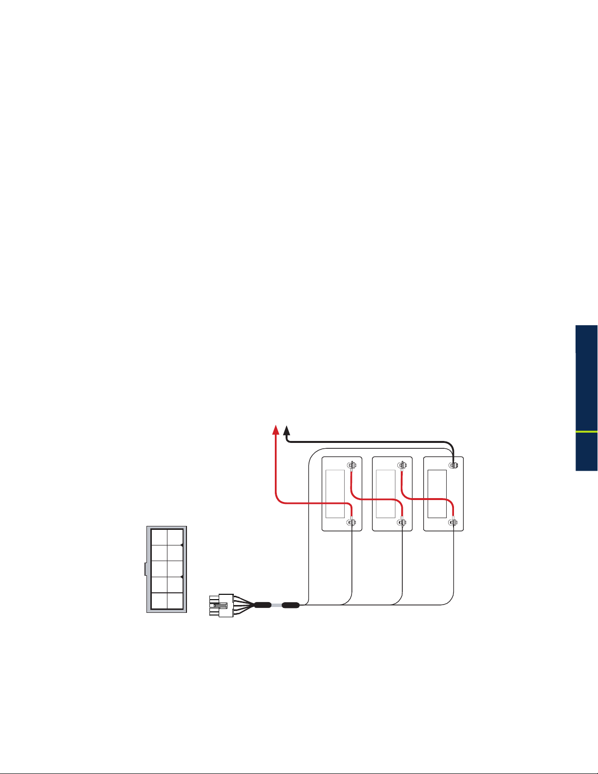
1.0 Introduction, continued
1.3 Alpha XM3-HP CableUPS Layout, continued
1.3.4 Smart AlphaGuard, continued
1.3.4.2 Connections
The connection from the embedded SAG to the battery strings are made with one of the
orderable wire kits. Kits for one, two, three, or four stings are available. Kits are also
available that mate to the external AlphaGuard wire kit. The SAG wire kit consists of a
string 36V positive and a string negative that are common for all strings. For each string
(A, B, C and D), there are two additional wires that must be connected.
Wire kits
New install with embedded SAG
1 string Battery harness p/n 875-848-20
2 string Battery harness p/n 875-848-21
3 string Battery harness p/n 875-848-22
4 string Battery harness p/n 875-848-23
Upgrade with external AlphaGuard wire kits in place
1 string Battery harness p/n 875-910-20
2 string Battery harness p/n 875-910-21
3 string Battery harness p/n 875-910-22
4 string Battery harness p/n 875-910-23
1
6
2
7
8
3
4
9
10
5
Back of Plug
Adaptor Cable
SAG to Status Monitor p/n 876-003-20
(please contact Alpha Technologies Inc. for full details).
Single battery string
A single string system must use String A on the wire harness.
(String -) 0V
Red
Black
NEG(-) NEG(-) NEG(-)
3A 2A 1A
POS(+)
Black, Pin 5
A/B/C/D NEG
Red, Pin 9
Vbatt 3A 36V
POS(+) POS(+)
Vbatt 2A 24V
Orange, Pin 4
Vbatt 1A 12V
Brown, Pin 10
1.0 Introduction
Fig. 1-11, Single Battery String Wiring Diagram (w/ embedded SAG Harness depicted)
29017-882-B0-001 Rev. C2 (10/2013)
Page 30
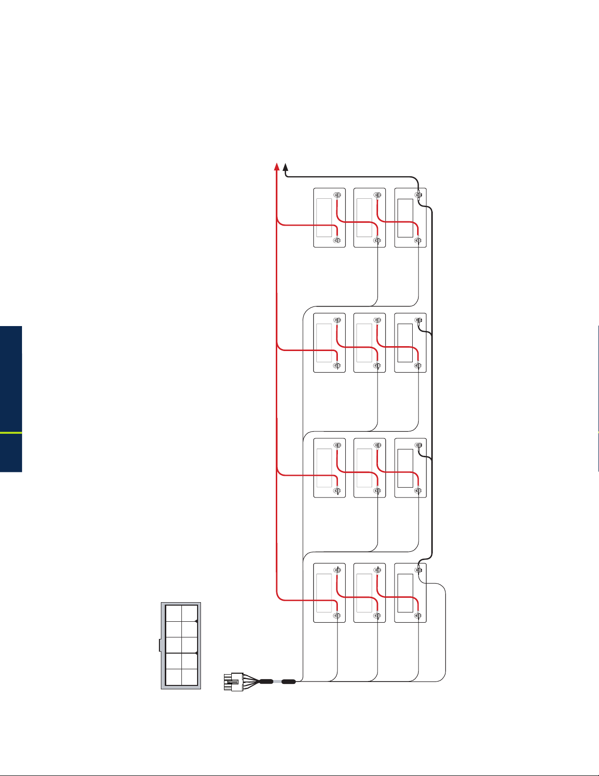
1.0 Introduction, continued
1.3 Alpha XM3-HP CableUPS Layout, continued
1.3.4 Smart AlphaGuard, continued
1.3.4.2 Connections, continued
Multiple battery strings
A system with multiple strings must use String A as the rst string, B as the second, C
as the third and D as the fourth.
To XM3
Black
Red
NEG(-) NEG(-) NEG(-)
3D 2D 1D
1.0 Introduction
POS(+)
NEG(-) NEG(-) NEG(-)
3C 2C 1C
POS(+)
NEG(-) NEG(-) NEG(-)
3B 2B 1B
POS(+)
POS(+) POS(+)
White, Pin 6
Vbatt 2D 24V
POS(+) POS(+)
Violet, Pin 7
Vbatt 2C 24V
POS(+) POS(+)
Gray, Pin 1
Vbatt 1D 12V
Blue, Pin 2
Vbatt 1C 12V
30
Green, Pin 8
1
6
2
7
8
3
4
9
10
5
Back of Plug
Vbatt 2B 24V
NEG(-) NEG(-) NEG(-)
3A 2A 1A
POS(+)
Vbatt 3A 36V
POS(+) POS(+)
Red, Pin 9
Vbatt 2A 24V
Orange, Pin 4
Vbatt 1B 12V
Yellow, Pin 3
Vbatt 1A 12V
Brown, Pin 10
Black, Pin 5
A/B/C/D NEG
Fig. 1-12, Multiple Battery String Wiring Diagram (w/ embedded SAG Harness depicted)
017-882-B0-001 Rev. C2 (10/2013)
Page 31

1.0 Introduction, continued
1.3 Alpha XM3-HP CableUPS Layout, continued
1.3.4 Smart AlphaGuard, continued
1.3.4.3 Alarms
The alarms are available through the LEDs and through the status monitoring card.
Denitions – SAG Alarms via Class Information Base (CIB)
Miswired – PS Minor
The SAG will verify a string is correctly wired before it will add it to the list of battery
strings to balance. If it detects the wires are reversed or only one battery is connected,
the alarm will activate. This alarm may also activate if a battery is outside the valid
voltage range of 9.9V to 15.7V.
High delta mean – PS Minor
The SAG compares all measured voltages to a calculated mean voltage. This is the ideal
voltage of the battery based on the total string voltage divided by the total number of
batteries in the string. The alarm activates immediately if a battery in the string gets more
than 500mV from the calculated mean voltage.
Check battery – PS Minor
The SAG keeps track of the balancing duration of all valid strings. If a string has a
battery that will not balance to within 150mV of the calculated ideal battery mean with
three weeks of balancing, then the alarm will be set. The suspect battery will be agged
in the status monitor information. The whole string should be checked as two suspect
batteries can cause an alarm on a good battery.
Stuck relay – PS Minor
Relays isolate the battery strings. The SAG provides a safety measure by verifying that
the relays have opened before it turns on a new string. The SAG will activate the alarm
and discontinue balancing until the alarm has cleared if the relays do not open properly.
No Harness – PS Minor
The SAG will verify that there is a harness connected before evaluating any other alarms.
Not Calibrated – PS Minor
The SAG checks the calibration data stored in memory to ensure the voltage readings
are accurate. If the data is not present, the alarm is activated.
1.0 Introduction
31017-882-B0-001 Rev. C2 (10/2013)
Page 32

1.0 Introduction, continued
1.3 Alpha XM3-HP CableUPS Layout, continued
1.3.4 Smart AlphaGuard, continued
1.3.4.4 LEDs
The LEDs provide visual indications of the current state of the SAG and any alarms that
are present.
LED ALARM STATES
LED
name
Color State Function
Off No power to SAG
Unit is on and communicating
Solid
with Power Supply or in Rest
mode
Active Green
Flash (90% on / 10% off)
Unit is on and not communicating
with Power Supply
Flash (50% on / 50% off) Actively balancing
Flash (10% on / 90% off) Powersave mode
Normal operation
No string wires connected
High delta mean
Check battery alarm
String A missing
STRG A
STRG B
STRG C
STRG D
(ALARMS)
Red
Off
Flash (50% on / 50% off)
Flash (10% on / 90% off) Stuck relay alarm
String miswired
Solid
ALL STRG
Battery outside valid range
No harness connected or all
strings are miswired
1.0 Introduction
Table 1-4, Smart AlphaGuard LED Alarm States
SAG front panel
Fig. 1-13, SAG Front Panel
32
017-882-B0-001 Rev. C2 (10/2013)
Page 33

1.0 Introduction, continued
1.3 Alpha XM3-HP CableUPS Layout, continued
1.3.4 Smart AlphaGuard, continued
1.3.4.5 Troubleshooting
High delta mean alarm during charging
A high delta mean alarm during charging is usually seen when one battery has either
higher or lower capacity than the other two batteries. This may be seen on initial install
of unbalanced batteries. Verify that the alarm clears within 7 days. Otherwise, investigate
the batteries.
High delta mean during discharging
A high delta mean alarm during discharging is usually seen when one battery has either
higher or lower capacity than the other two batteries. The SAG cannot compensate
for reduced capacity batteries in discharge mode to maintain balance. Investigate the
batteries.
Miswired string alarm during discharging/charging
A miswired string alarm occurs when a battery voltage is not within the specied valid
battery range of 9.9V to 15.7V, but the other batteries are in valid ranges. During
discharge, a battery with a much lower capacity will have a voltage that is much lower
than the others in the string. This can cause the low capacity battery voltage to fall
outside the limits of a valid battery, and the SAG may identify the string as miswired.
Investigate the batteries.
Maintenance required and stuck relay alarm at the same time
This is normal alarm operation. A stuck relay alarm will trigger an alarm in the SAG and
the XM3 will trigger a maintenance required alarm. Replace the unit if the alarm does not
clear itself.
Preventive maintenance required and high delta mean alarm at the same time
This is normal alarm operation. A high delta mean alarm will trigger an alarm in the SAG
and the XM3 will trigger a preventive maintenance required alarm. Investigate the battery
condition if the alarm persists.
1.0 Introduction
33017-882-B0-001 Rev. C2 (10/2013)
Page 34

1.0 Introduction, continued
1.3 Alpha XM3-HP CableUPS Layout, continued
1.3.5 Inverter Module Overview
The removable Inverter Module provides uninterrupted power to the ferroresonant transformer
(via the batteries) during utility failures. During normal operation, the inverter charges the
batteries using a three-, four- or ve-stage (Bulk, Accept, Refresh, Rest and Float) charging
protocol determined by the charger setting and battery type.
1
Smart Display: All operational functions, system testing, programmable items and alarms are
available via the Smart Display panel on the front of the Power Supply.
2
Softkeys: Provide access to the various menus and submenus within the Alpha XM3-HP.
3
Output LED: Indicates output state of the Alpha XM3-HP.
4
Alarm LED: Indicates Alarm condition.
Self Test button: Initiates Self Test.
5
6
Local/Remote Indicator Connector: Indicates alarm condition to exterior lamp.
The Precision Temperature Sensor (PTS): Plugs directly into the Temperature Probe (RJ-11C
7
type) Connector.
1.0 Introduction
Battery Circuit Breaker: Controls battery DC power to the inverter.
8
9
Battery Cable Input Connector: The battery cable connector plugs directly into the Inverter
Module’s battery input connector. The connector is polarized and ts in one direction only.
1
3
4
2
5
6
7
8
34
9
Fig. 1-14, Inverter Module Connections
017-882-B0-001 Rev. C2 (10/2013)
Page 35

1.0 Introduction, continued
1.3 Alpha XM3-HP CableUPS Layout, continued
1.3.6 Optional DOCSIS Status Monitoring Modules
The Power Supply supports several Alpha communication modules which may be ordered
factory-installed or as a user-installed eld upgrade (for full installation instructions refer to the
communication module technical manual). The AlphaNet DSM3 and IDH4 Series Embedded
DOCSIS Transponders allow monitoring of Alpha power supplies through existing cable network
infrastructure. Advanced networking services provide quick reporting and access to critical
powering information.
The communications modules utilize Simple Network Management Protocol (SNMP) and
standard Management Information Bases (MIBs) to provide network status monitoring and
diagnostics. A Web interface enables authorized personnel direct access to advanced diagnostics
using a common Web browser. This manual addresses all models and is based on the DSM3x,
which has the complete feature set. Table 1-5 compares the differences between the transponder
models.
1.0 Introduction
35017-882-B0-001 Rev. C2 (10/2013)
Page 36

1.0 Introduction, continued
1.3 Alpha XM3-HP CableUPS Layout, continued
1.3.6 Optional DOCSIS Status Monitoring Modules, continued
1.0 Introduction
Status Monitoring Features
AlphaNet DPM or IDH4L
AlphaNet DSM3 or IDH4
AlphaNet DSM3x or IDH4x
Fig. 1-15, AlphaNet Series Communications Modules
AlphaNet DSM Series AlphaNet IDH4 Series
DPM DSM3 DSM3x IDH4L IDH4 IDH4x
DOCSIS 2.0, ANSI/SCTE HMS Compatible x x x x x x
SNMP, Web and Ethernet Craft Access x x x x x x
Single Image Firmware x x x x x x
Supports XM3-HP x x x x x x
Single Processor Design 1-IP, 2-IP x x x x x x
Harness Installation and RF Level Indicators x x x x x x
Max. Number of Battery Strings Monitored 4, Requires SAG-4 option 2 4 4, Requires SAG-4 option 2 4
External Equipment Monitoring and Control x x x x
Multiple PS and Generator (AlphaBus) x x
Supports IPv6 Addressing x x x
Table 1-5, Comparative Features, AlphaNet Series Communications Modules
36
017-882-B0-001 Rev. C2 (10/2013)
Page 37

2.0 Installation
2.1 Installation Procedure
The Alpha XM3-HP CableUPS can be shelf-mounted within a variety of Alpha enclosures and secured with an
internal tamper-resistant security screw kit. The installer must read and follow all safety instructions starting
on page 9 and the preliminary inspection below prior to installation of the Power Supply.
CAUTION!
Read the Safety Precautions, Utility Power Connection Notes and Grounding Connection Notes (pages
9-15) before installing the Power Supply.
2.1.1 Pre-installation Inspection
1. Remove the Power Supply from the shipping container. Conrm the Power Supply, including
2. During shipping, components might shift. Carefully inspect the Power Supply and other contents
3. Do not attempt to install a Power Supply without rst passing a complete pre-installation
the Precision Temperature Sensor and all other ordered options, are included.
for possible shipping-related failures, such as loosened or damaged connectors. If any items
are damaged or missing, contact Alpha Technologies or the shipping company immediately.
Most shipping companies have a short claim period.
inspection.
NOTE:
Use the original shipping container if the Power Supply needs to be returned for service. If the original container is
not available, make sure the unit is well packed with at least three inches of shock-absorbing material to prevent
shipping damage.
CAUTION!
Do not use popcorn-type material. Alpha Technologies is not responsible for damage caused by
improper packaging of returned units.
2.1.2 Internal Security Screw Kit Installation
The security screw kit included with the XM3-HP Power Supply provides the hardware for
securing the power supply to its enclosure. The security key for the included security screw is
NOT in the installation kit and must be purchased separately from Alpha. The customer may
supply their own tamper resistant/security fastener if desired.
WARNING!
• Only qualied service personnel should perform this procedure.
• Use EXTREME CAUTION when drilling into the enclosure. Clear all equipment, wiring, and
batteries from the area into which you are drilling.
• Lead-acid batteries contain dangerous voltages, currents and corrosive material.
2.0 Installation
NOTE:
• This security enhancement is available on the XM3-HP with a manufacturing code of 2013 and newer.
• Enclosure and Power Supply unit may differ slightly from the gures. Use as reference only.
Required Materials:
• Security Screw Kit, p/n 746-316-20
• Alpha-01 Security Key, p/n 647-188-10
017-882-B0-001 Rev. C2 (10/2013)
• 3/8" Hand Drill
• 13/32" (#Y) Drill Bit
• Center Punch
• 3/8" Socket and Torque Wrench
37
Page 38

2.0 Installation, continued
2.1 Installation Procedure, continued
2.1.2 Internal Security Screw Kit Installation, continued
Kit Includes:
A. 3/4" x 1/4" Aluminum Spacer, p/n 640-174-10
B. 1-1/2" SS Flat Washer, p/n 633-015-12
C. 5/16-18 X 1" SS Security Screw, p/n 647-189-12
(*) – Customer may supply their own tamper resistant/
security fastener. If so, do not use kit supplied screw.
A
B C
2.0 Installation
Not Included:
D. Alpha 01 Security Screw Key, p/n 647-188-10
Installation Procedure:
1. Locate the security screw mounting location on the XM3-HP Power Supply (see Fig. 2-2).
2. Mark the location of the XM3-HP security screw hole on the enclosure shelf.
3. Using the 13/32" drill bit, drill the hole for the security screw. Remove all metal shavings from
the enclosures.
4. Position the 1/4" aluminum space over the hole (use the center punch to locate the spacer
directly over the hole).
5. Position the XM3-HP Power Supply with the security hole over the drilled hole and spacer (use
the center punch to hold the spacer in place while situating the power supply) (see Fig. 2-3).
6. Install the 5/16-18 X 1" SS Security Screw and 1-1/2" SS Flat Washer from the underside
of the shelf. If installing the supplied 5/16-18 X 1" SS Security Screw, torque to 26 ft-lbs
(35.2 Nm). If installing a different security screw, follow the manufacturer’s recommendations
for torque.
Power Supply Bottom View
D
Figure 2-1, Required Materials
38
Figure 2-2, Security Screw Mounting Location
Security Screw
Mounting Location
1/4" Spacer
SS Washer
Security Screw
Figure 2-3, Power Supply/Enclosure Shelf Security Screw Stack Up
017-882-B0-001 Rev. C2 (10/2013)
Page 39

2.0 Installation, continued
2.2 XM3-HP Start-Up Procedure
2.2.1 Parts and Connections
11
16
17
5
8
10
9
13
18
19
20
15
12
2
4
14
1
3
7
6
Fig. 2-4, Installation of XM3-HP
Battery Connector to Inverter
1
Precision Temperature Sensor (PTS)
2
Negative Terminal to Center Battery
3
and PTS
Battery Breaker
4
Smart AlphaGuard Harness
5
Positive Battery Terminals to Smart
6
AlphaGuard (3, Red)
Negative Battery Terminal (1, Black)
7
8
APPS Card
6
11
Local Remote Indicator (LRI)
LRI Interface to Inverter
12
13
Smart Display
Transponder Battery Sense Harness connection
14
point
15
RF Connector to Transponder
16
Service Power Inserter (SPI)
17
Alarm Intrusion Tamper Switch
18
Transponder Tamper Switch Connector
6
2.0 Installation
9
Grounded Surge Protector
10
AlphaDOC Dual Output Connectors
19
Ethernet (Web Page Interface)
20
Tri-color LED Tx/Rx Power Levels
WARNING!
Verify battery voltage, cable color, connection and polarity are correct before proceeding.
017-882-B0-001 Rev. C2 (10/2013)
39
Page 40

2.0 Installation, continued
2.2 XM3-HP Start-Up Procedure, continued
2.2.2 Battery Installation Options and Wiring Diagram
Load batteries into cabinet with the positive terminals (+) facing forward. Battery strings are
lettered A through D; batteries are numbered 1 through 3, from right to left.
To Power Supply
1
Red
Black
PTS
2
(String -) 0V
3
NEG(-) NEG(-) NEG(-)
7
2.0 Installation
A3
POS(+)
5
Black, Pin 5
A/B/C/D NEG
Red, Pin 9
Vbatt 3A 36V
A2
POS(+) POS(+)
Vbatt 2A 24V
Orange, Pin 4
A1
66
6
Vbatt 1A 12V
Brown, Pin 10
Fig. 2-6, Precision Temperature
Sensor (PTS), p/n 746-331-20
Fig. 2-5, Battery Wiring Diagram
(w/ embedded SAG option depicted)
Smart AlphaGuard (Embedded) — use Battery Harness, p/n:
875-848-20 for one string
875-848-21 for two strings
875-848-22 for three strings
875-848-23 for four strings.
AlphaGuard (external) — use Battery Harness, p/n 875-090-32.
Upgrade existing external AlphaGuard to Smart AlphaGuard — use Retrot Cable, p/n:
875-910-20 for one string
875-910-21 for two strings
875-910-22 for three strings
875-910-23 for four strings.
Adapt Smart AlphaGuard harness to legacy DSM3/DSM3x connector — use Adaptor Cable, p/n 876-003-20.
40
DSM3 (1 battery string) — use Battery Sense Harness, p/n 874-842-21 (Not required if Smart AlphaGuard is installed with
its sense harness).
DSM3 (2 battery strings) — use Battery Sense Harness, p/n 874-842-28 (Not required if Smart AlphaGuard is installed with
its sense harness).
DSM3x (3 battery strings) — use Battery Sense Harnesses, p/n 874-842-21 and 874-842-28 (Not required if Smart
AlphaGuard is installed with its sense harness).
DSM3x (4 battery strings) — use Battery Sense Harness, p/n 874-842-20 and 874-842-28 (Not required if Smart
AlphaGuard is installed with its sense harness).
NOTE:
A NOTE provide additional information to help complete a specic task or procedure.
017-882-B0-001 Rev. C2 (10/2013)
Page 41

2.0 Installation, continued
2.2 XM3-HP Start-Up Procedure, continued
2.2.2 Battery Installation Options and Wiring Diagram, continued
2.2.2.1 Threaded Insert Terminals
CAUTION!
Threaded insert terminals require the use of 3/4" (19mm) bolts. The use of 1" (25.4mm) bolts will seriously
damage the battery. The only exception is the terminal with the large spacer for the in-line fuse link. Apply
NO-OX grease on all exposed connections.
Torque all nuts and bolts to 110in-lbs (12.43N-m).
3/4" (19mm) x 1/4-20 Bolt
Split Washer
Flat Washer
Battery Cable
Battery Sense
Cable or PTS
Spacer
Battery Terminal
Fig. 2-7, Battery Terminal Bolt Stack-up Fig. 2-8, Fuse Bolt Stack-up
2.2.3 120/240V Conguration Procedure
NOTE:
This procedure is for the XM3-918D-HP only.
1/4-20 Nut
Split Washer
Flat Washer
Battery Cable
Flat Washer
3/4" (19mm) x 1/4-20 Bolt
Fuse
2.0 Installation
Procedure:
1. Remove the Inverter Module to access the Transformer Harness (see Fig. 2-9).
2. Connect the appropriate connector to the Transformer Harness. For the 120V
Fig. 2-9, Transformer Harness
017-882-B0-001 Rev. C2 (10/2013)
conguration, connect the end with two wires. For the 240V conguration, connect the end
with only one wire (see Fig. 2-10).
120V
p/n 744-281-20
240V
p/n 744-281-21
Fig. 2-10, 120/240V Connector
41
Page 42

2.0 Installation, continued
2.2 XM3-HP Start-Up Procedure, continued
2.2.3 120/240V Conguration Procedure, continued
3. Connect the correct power cord to the Power Supply (see Fig. 2-11)
4. Upon start up, the Input Voltage Setting screen will appear. Select correct voltage to proceed
(see Section 3.3, Smart Display Menus). The Input Voltage Setting screen displays for ve
minutes before reverting to the previous settings.
CAUTION!
• If 240V is connected to the Power Supply input when the transformer has the 120V plug installed, the
input circuit breaker will trip.
• If the 120V setting is selected when the input is 240V, the Input Failure alarm will activate and the
Power Supply will transfer to inverter if batteries are connected.
• If the incorrect voltage setting is selected, change the settings by either cycling the power again or
accessing the Input Voltage Setting in the Power Conguration menu.
XM3-918D-HP 90V/0.4A
INP V SETTING 120V
ENTR
h i
ESC
2.0 Installation
120V 240V
Fig. 2-11, Line Cord Plugs
Fig. 2-12, Input Voltage Setting Screen
2.2.4 63/89VAC Output Voltage Reconguration Procedure
WARNING!
Remove all sources of power to unit before performing the following procedure.
Tools Required:
Small at-blade screwdriver
Procedure:
1. To access Output Voltage Terminal, remove the
Inverter Module (see Fig. 2-13).
2. Loosen the terminal screw and move the Output
Voltage Wire to the desired output voltage position
on the Output Voltage Terminal (see Fig. 2-14).
Output
Voltage
Terminal
Fig. 2-13, Removing Inverter Module
and Output Voltage Terminal Location
63V
89V
42
3. Torque the terminal screw to 7in-lbs (0.79N-m) to
secure the Output Voltage Wire.
4. Replace the Inverter Module.
Output
Voltage
Wire
Fig. 2-14, Voltage Wire Position
017-882-B0-001 Rev. C2 (10/2013)
Page 43

2.0 Installation, continued
2.2 XM3-HP Start-Up Procedure, continued
2.2.5 Optional Smart AlphaGuard and Alpha APPS Installation
WARNING!
Remove all sources of power to unit before performing the following procedure.
Tools required:
#2 Phillips screwdriver
Procedure:
1. Remove the three fasteners securing
the front panel (see Fig. 2-15).
2. With the front panel open, install the
APPS card by pressing it rmly onto
the standoff (A) and fastening the
6-32 screw (B) (see Fig. 2-16).
3. Connect the ribbon cable (C) and
ensure the locking clips are closed.
4. Install the SAG card by pressing it
rmly onto the two standoffs (D) and
fastening the two 6-32 screws (E)
(see Fig. 2-17).
5. Connect the ribbon cable (F) and
ensure the locking clips are closed.
6. Reinstall the front panel and secure
with the fasteners removed in Step 1.
Fig. 2-15, Front Panel Fastener Locations
A
Fig. 2-16, APPS Card Standoff, Screw and
Ribbon Cable Locations
D
D
B
2.0 Installation
C
E
E
F
017-882-B0-001 Rev. C2 (10/2013)
Fig. 2-17, SAG Card Standoffs, Screws and
Ribbon Cable Locations
43
Page 44

2.0 Installation, continued
90V
75V
60V
ALM/
RDY
RST
FLASH = MIN ALM
~
N
SOLID = MAJ ALM
STRG A
STRG B
STRG C
STRG D
TPR
Rx/Tx PWR
E
T
H
A
/
B
C
/
D
C
O
M
REG
DS
ACT
LNK
BLUE = WARN
RED = OUT
GRN = OK
ON
OFF
O
I
i
~
N
~
N
ALM/
RDY
RST
FLASH = MIN ALM
OUTPUT 2
~
N
N + 1
SOLID = MAJ ALM
STRG A
STRG B
STRG C
STRG D
TPR
Rx/Tx PWR
E
T
H
A
/
B
C
/
D
C
O
M
REG
DS
ACT
LNK
BLUE = WARN
RED = OUT
GRN = OK
ON
OFF
O
I
i
~
N
OUTPUT 1
~
N
SPI #1
SPI #1
OUTPUT 2
N + 1
OUTPUT 1
1
2.2 XM3-HP Start-Up Procedure, continued
2.2.5 Optional Smart AlphaGuard and Alpha APPS Installation, continued
Procedure:
7. Connect the SPI (16) to the AlphaDOC Dual Output
Connector (10) (see Fig. 2-18).
16
5
8. Connect the SAG Harness to the SAG Connection
(5) (see Fig. 2-18).
10
Fig. 2-18, SPI, AlphaDOC and SAG Harness
Connections
2.2.6 Optional N+1 Congurations
Because the N+1 option provides a second output, the Intelligent CableUPS can function as an N+1
redundant supply system. The N+1 option also provides programmable current limits for two output
channels, which protects system components by shutting down the load during overcurrent and short
circuit conditions. Adding a DOC with N+1 to a secondary power supply enables both power supplies to
be connected in a “dual redundancy” conguration to protect two critical loads.
2.0 Installation
44
Wire Kit (Alpha P/N: 875-994-20)
1
Fig. 2-19, N+1 Conguration
017-882-B0-001 Rev. C2 (10/2013)
Page 45

2.0 Installation, continued
75V
60V
SPI #1SPI #1
SPI #1
~
N
ALM/
RDY
RST
FLASH = MIN ALM
~
N
SOLID = MAJ ALM
STRG A
STRG B
STRG C
STRG D
TPR
Rx/Tx PWR
E
T
H
A
/
B
C
/
D
C
O
M
REG
DS
ACT
LNK
BLUE = WARN
RED = OUT
GRN = OK
ON
OFF
O
I
i
~
N
OUTPUT
ALARM
TEST
BATTERY
TEMP
LRI
BATTERY
INPUT
BATTERY
BREAKER
N + 1
~
N
ALM/
RDY
RST
FLASH = MIN ALM
OUTPUT 1
~
N
OUTPUT 2
SOLID = MAJ ALM
STRG A
STRG B
STRG C
STRG D
TPR
Rx/Tx PWR
E
T
H
A
/
B
C
/
D
C
O
M
REG
DS
ACT
LNK
BLUE = WARN
RED = OUT
GRN = OK
ON
OFF
O
I
i
~
N
OUTPUT
ALARM
TEST
BATTERY
TEMP
LRI
BATTERY
INPUT
BATTERY
BREAKER
N + 1
OUTPUT 1
OUTPUT 2
SPI #2
1
1
90V
2.2.6 Optional N+1 Congurations, continued
The N+1 ports are used in redundant system congurations where multiple power supplies are housed
in a single enclosure. In the event of a power supply failure, a redundant power supply (with an optional
DOC with N+1 board installed) is automatically switched into service with approximately a 8ms delay. This
feature is part of the DOC with N+1 option.
This provision also protects system components by shutting down the load during overcurrent and short
circuit conditions. Adding a DOC with N+1 in the secondary power supply enables both power supplies to be
connected in a “dual redundant” conguration so the system can protect two critical loads (see Fig. 2-20).
NOTE:
The N+1 unit and the primary unit cannot be loaded over 50% of rated capacity when congured as shown below.
When the power supply is in N+1 operation, the active alarm menu screen will display (see Figure 2-21).
Additionally, the Output Voltage and Output Current display in the upper right hand corner of the Smart
Display will show 0 Volts and a value for the Output Current Amperage (e.g. 0V/10.8A). This Output
Current Amperage is the sum of output terminals. By pressing the softkey below the PWR menu the
Active Alarms menu will display (see Figure 2-22).
NOTE:
When N+1 is in use, the displayed Output Current will not agree with the Output Current CIB on the remote status
monitoring web-page, which will show 0 Volts for Output Voltage and 0 Amps for the Output Current. However, the
017-882-B0-001 Rev. C2 (10/2013)
Output Current displayed on the Smart Display will be correct for the output terminals.
Wire Kit (Alpha P/N: 875-994-20)
1
2.0 Installation
Fig. 2-20, Dual Redundancy N+1 Conguration
XM3 0V/10.8A
Fig. 2-21, Active Alarm Screen Fig. 2-22, N+1 In Use Alarm Screen
ACTIVE ALARMS
**
ALM OK OK OK
**
PWR BATT COMM APPS
ACTIVE ALARMS
**
INPUT FAILURE
N+1 IN USE
**
ESC
45
Page 46

2.0 Installation, continued
2.2 XM3-HP Start-Up Procedure, continued
2.2.7 Communications DOCSIS Status Monitoring, continued
2.2.7.1 DOCSIS Status Monitor Front Panel Connections
1. Connect Battery Sense Wire Harness to the A/B, C/D connection points (14) on the
transponder. The connection (14) is not required for individual battery monitoring if
the Smart AlphaGuard option is deployed. For XM3 units with the Smart AlphaGuard
option, connect the Battery Harness (5) to the AlphaGuard connection located on the
left side of the XM3 Power Supply.
2. Connect Tamper Switch Wire Harness to the TPR Connector (18).
3. Connect the RF drop (15) and make front panel connections as shown below for
the DSM3. The DOCSIS specication for downstream power level is +/-15 dBmV.
However, for optimal performance, set the level as close to 0 dBmV as possible.
To Battery Sense Wire
2.0 Installation
Ethernet Connector
Green/Blue/Red
LED Indicators
Harnesses
18
Tamper Switch Connector
19
20
15
RF Cable to Headend
9
14
Required
Grounded Surge Protector
(Alpha p/n 162-028-10 or equivalent)
Fig. 2-23, DOCSIS Status Monitor Front Panel Connections
46
017-882-B0-001 Rev. C2 (10/2013)
Page 47

2.0 Installation, continued
2.2 XM3-HP Start-Up Procedure, continued
2.2.7 Communications DOCSIS Status Monitoring, continued
2.2.7.2 LED Status Verication
Step Communications State ALM/RDY Downstream (DS) Registration (REG) Rx/Tx Power Communications (COM)
Transponder Initializing/Searching
1
for Downstream DOCSIS channel
DOCSIS Channel locked Completing upstream and network
2
registration
Online - Registration Complete
3
Verify the DSM3 LEDs behavior is as follows:
LEDs and Indications (20)
Flashing
(Green)
Flashing
(Green)
Flashing
(Green)
Flashing OFF OFF Flashing
ON Flashing ON (Green) Flashing
ON ON ON (Green) Flashing
DSM3 Series fully functional
4
Flashing
(Green)
ON ON ON (Green) Bursts when Communicating
Refer to Step 4 in the above table for normal LED behavior when the DSM3 is fully functional.
• Blue Rx/Tx Power LED indicates Rx/Tx Power at a warning level. Make the necessary RF level
adjustments.
• Red Rx/Tx Power LED indicates Rx/Tx Power at an alert level. Make the necessary RF level
adjustments.
LED Color Rx Range (dBmV) Tx Range (dBmV)
Green +10 to -10 0 to +50
Blue +15 to +10 and -10 to -15 +50 to +55
Red >+15 and <-15 >+55
Table 2-1, DSM3 LEDs Behavior
2.0 Installation
017-882-B0-001 Rev. C2 (10/2013)
47
Page 48

2.0 Installation, continued
2.2 XM3-HP Start-Up Procedure, continued
2.2.8 Power Module Conguration and Installation Procedure
NOTE:
Before applying power, verify Power Supply rating is matched to AC input utility. Verify a low-resistance
ground is installed in accordance with your local electrical regulatory authority.
CAUTION!
Batteries are an important part of the Power Supply. Properly install and test all batteries, battery
connections and battery cables before you connect them to the Power Supply.
1. Route the Local/Remote Indicator cable down through the opening in the left side of the shelf and
back up through the opening in the right side of the shelf and connect.
NOTE:
Note: For existing LRI installations, use LRI adapter kit, p/n 875-952-20.
2. After wiring battery cable kit, battery sense cables and PTS as shown in Section 2.2.2, Battery
Installation Options and Wiring Diagram, verify DC breaker is OFF, then connect battery cable to
Inverter Module.
2.0 Installation
3. Connect the Smart AlphaGuard wire harness to Smart AlphaGuard port.
4. Connect Precision Temperature Sensor to Inverter Module.
5. Connect transponder, RF Input cable, and the tamper switch (if installed). Refer to Section 2.2.7.1,
DOCSIS Status Monitor Front Panel Connections for communication module connections.
6. For new installations, skip to step 10.
7. For upgrading existing sites, install Service Power Supply (see Service Power Supply documents)
and remove existing Power Supply.
8. Thoroughly inspect output connectors for abnormal heating or damaged housing; replace if
necessary.
9. Verify SPI (16) switch is in “ALT” position.
10. Connect the SPI (network load) to the Output 1 connector.
11. Connect the second isolated load / auxiliary load (i.e., fan) to the Output 2 connector.
12. Turn on AC breaker (located on enclosure) and verify correct (per unit’s nameplate voltage) utility
voltage at outlet; if correct, plug in line cord to the utility outlet. For XM3-918D-HP models, the utility
voltage may not match the nameplate voltage when switching between 120V and 240V.
13. Turn battery breaker ON. For XM3-918D-HP models, select the Input Voltage Setting by pressing
ENTR.
48
14. Toggle SPI switch to ON.
15. Verify no alarms are present after power up initiation (it may take up to 60 seconds for alarms to clear;
APPs alarms may take longer). Alarms may be veried on the LCD display or Alarm LED.
017-882-B0-001 Rev. C2 (10/2013)
Page 49

2.0 Installation, continued
2.2 XM3-HP Start-Up Procedure, continued
2.2.8 Power Module Conguration and Installation Procedure, continued
ALARM LED (red)
XM3-918-HP 90V/0.4A
**ACTIVE ALARM**
OK
PWR
PM
BATT
ALM
COMM
OK
APPS
OUTPUT LED (green)
1 2
1
2
Condition Output Alarm
Normal On Off
Minor Flash Off
Major Flash Flash
Output Off Off Flash
Fig. 2-24, Active Alarm Table
16. If alarms do not clear after 60 seconds, press the menu key with ALM indicated above it to see the
ACTIVE ALARM list for the selected key.
17. Press UP or DOWN to select the alarm of interest.
18. Press ENTR to select the alarm and display diagnostic information. Press ESC to return to the alarm
list.
19. Enter Battery Type (or parameters) and number of battery strings. Battery type entries can be made
on the LCD.
20. Enter the battery DATE code and the MHOs (conductance) readings. Battery date and MHOs entries
can be made on the LCD (see Figs. 2-25 and 2-26).
BATT A1 DATE 1/10
↑↓
ENTR to shift eld
ENTR
Adjust Value
↑ ↓
ESC
Fig. 2-25, Enter Battery Date Code
BATT A1 MHOs 1000M
↑↓
ENTR to save
ENTR
Adjust Value
↑ ↑
ESC
Fig. 2-26, Enter Battery MHOs Reading
NOTE:
Battery MHOs and Date Code can only be set after DOCSIS transponder has registered with CMTS.
Please wait 3 minutes after power up to enter Battery MHOs measurements.
2.0 Installation
017-882-B0-001 Rev. C2 (10/2013)
49
Page 50

2.0 Installation, continued
2.2 XM3-HP Start-Up Procedure, continued
2.2.8 Power Module Conguration and Installation Procedure, continued
21. Once the unit is running on line voltage, perform a Self Test by pressing and holding the test
button for 1-2 seconds with a pen (or similar object). Wait for Self Test completion before
proceeding (see Section 3.1.1, Self Test Operation).
NOTE:
If the unit is operating from batteries, the Self Test will not initiate. Check input breaker and input line cord.
22. Perform standby test by shutting off utility breaker and verifying unit goes into standby and
supports the load.
23. Re-apply AC power and verify unit goes to Line Mode.
NOTE:
Two output connectors will be present on the side of the front panel whether or not the optional AlphaDOC
is installed. If an AlphaDOC is not installed, the output voltage (Output 1) will be present on both
connectors as the connectors are wired in parallel by means of a split ("Y") wiring harness. If an optional
AlphaDOC is installed, the split wiring harness is replaced with individiual wiring for Output 1 and Output 2
(SecondaryloadstobeconnectedtoOutput2).
2.0 Installation
NOTE:
The default language is set to English. Unless the XM3 is ordered preset to another language, the
language can be changed through the PWR CNFG (Power Conguration) menu. Pressing the PWR
(Power) softkey while in the OPERATION NORMAL screen opens the Power Info Menu display (the rst
letter of the top line will blink indicating it is the active line; shown in orange). Pressing ENTR from this
screen opens the PWR CNFG Menu. Scroll down to the SELECT LANGUAGE menu to set to the desired
language, see Figure 2-27.
PWR CNFG <ENTR>
OUTPUT VOLTS
OUTPUT CURR
ENTR ESC
50
Power Info Menu Default Range
PWR CNFG <ENTR>
Fig. 2-27, Select Language in PWR CNFG Menu
Power Cong Menu Default Range
SELECT LANGUAGE English Spanish
French
Portuguese
German
017-882-B0-001 Rev. C2 (10/2013)
Page 51

2.0 Installation, continued
2.2 XM3-HP Start-Up Procedure, continued
2.2.9 Local Verication of DOCSIS Transponder
To conrm successful hardware installation before leaving the installation site, verify network
connectivity and correct hardware interconnection.
The DS and REG LEDs on the front of the DSM3 Series should be ON solid green. This indicates
successful registration with the headend. In addition, the RF LED should also be ON solid green indicating proper RF power levels and the ALM/RDY LED should be blinking green for normal operation.
With the DSM3 Series used in conjunction with the XM3-HP Power Supply, network connectivity can
be veried via the COMM menu on the XM3 Smart Display. Figure 2-28 provides a list of parameters
available on the XM3 Smart Display populated with sample values.
COMM - GENERAL
COMM - EXTENDED
COMM - DIAGNOSITCS
ENTR ESC
i
i
COMM - FAULT
RF POWER LEVEL FAULT
SEE GENERAL MENU
ESC
NOTE: COMM-FAULT Menu
appears only if there is no RF
connection or RF interruption
occurs.
COMM - GENERAL
CM MAC ADDRESS
00:90:EA:A0:04:99
COMM GENERAL
CM MAC ADDRESS
00:90:EA:A0:04:99
CM IP ADDRESS
192.196.203.101
CM IPV6 ADR PREFIX*
2001:123:456:789
CM IPV6 ADR POSTFIX*
111:22 2: 33 3: 3 43 4
CPE MAC ADDRESS**
00:90:EA:A0:04:9A
CPE IP ADDRESS**
192.168.200.100
CM RECEIVE POWER
CM TRANSMIT POWER
DOWNSTREAM SNR
* Menu item available if
ESC
-12.9dBmV
34.5dBmV
33.8dB
DSM3 is provisioned in
IPv6 mode
** Menu item available if
DSM3 is provisioned in
Dual-IP mode
Fig. 2-28, COMM Menu Options
COMM - EXTENDED
COMM-EXTENDED
DSM MODEL/CONFIG
DSM MODEL/CONFIG
COMM - EXTENDED
DSM MODEL/CONFIG
DSM FIRMWARE VERSION
SYSTEM NAME
SYSTEM CONTACT
SYSTEM LOCATION
COMMON LOGICAL ID
DOCSIS CONFIG FILE
DSM SERIAL NUMBER
SYSTEM DEVICES 3-7*
SYSTEM DEVICES 6-7*
SYSTEM DEVICES 7-7*
CABLEWARE SERVER IP
* Menu item will populate
DSM3x CW - 8B
DSM3X CW-BB
i ii
i
ESC
ESC
DSM3X CW-8B
4.4.9.0_03.02_NA
ABC123 CABLE
JOHN DOE
123 BAKERVIEW
12345-3767 ALPHAWAY
ALPHA_DSM3.CM
A00499
IPU-1 SAG-1 DOC-1
XM3-1 APP-1 BTQ-1
UTL-1
192.168.200.151
for only Cableware
congured units
COMM-DIAGNOSTICS
COMM - DIAGNOSTICS
CABLE MODEM STATUS
CABLE MODEM STATUS
COMM - DIAGNOSTICS
CABLE MODEM STATUS
SYSTEM UPTIME
DOWNSTREAM FREQUENCY
DOWN MODULATION TYPE
UPSTREAM FREQUENCY
T3 TIMEOUTS
T4 TIMEOUTS
CODEWORD ERROR RATIO
MICROREFLECTIONS
CM RESETS
CM LOST SYNCS
LAST SNMP QUERY
OPERATIONAL
Operational
ii
ESC
ESC
OPERATIONAL
3 DAYS 05H:16M:59S
300.000 MHZ
256 QAM
15.000 MHZ
80360
8.20%
-5 DBC
Date/Time
51
10
5
NOTE: System Device menu items
are internal Alpha diagnostic codes.
The System Devices menu items will
populate based on the option cards
(SAG, APP, DOC) installed and the
number of external devices added to a
power system such as multiple XM3s
and/or AlphaGen.
2.0 Installation
017-882-B0-001 Rev. C2 (10/2013)
51
Page 52

2.0 Installation, continued
2.2 XM3-HP Start-Up Procedure, continued
2.2.10 Web Interface
Overview
The DSM3 Series Power Supply transponder provides an embedded Web server interface to
allow operations personnel the ability to connect locally or remotely via TCP/IP over Ethernet with
a laptop/computer to verify the status of common data points and to congure various operating
parameters.
2.2.10.1 Local Web Server Access
The DSM3 Series transponder’s Ethernet port (comparable to the Craft port on some
transponder models) will typically be used as a local connection point allowing the user
to connect directly to the DSM3 Series Web server interface to verify/congure common
communication parameters and view Power Supply status and battery values. The
Ethernet port on the DSM3 Series is a fully functional standard Ethernet port, capable of
providing all the functionality of any standard Ethernet connection.
To access the DSM3 Series transponder Web server locally utilizing a Web browser, use
the following procedure:
NOTE:
2.0 Installation
Fig. 2-29, DSM3 Series Web Page
(data values shown for illustration purposes only)
The following Web Browser settings should be
‘enabled’ for proper rendering/download of the
web pages:
• Java Script
• Cookies
• Activex Controls
• Downloads
• Active Scripting
• Show Pictures
These settings are typically enabled in the Web
Browser by default.
1. Connect a standard Ethernet cable (CAT5)
between the DSM3 Series transponder Ethernet
port (ETH) and a laptop or computer’s network
interface port.
2. Launch a Web browser.
3. Enter the transponder's default IP address
(192.168.100.1) into the Web browser’s address
eld.
4. The transponder’s Web server home page will
appear (Fig. 2-29). Note:FortheDSM3Series,
thismaytakeupto45secondswhenthe
transponderisinitiallypoweredupwithno
RFconnection.
5. Click the Language menu to select a desired
language for the text information on the Web
page. The language choices are English
(default), Spanish, Portuguese, French &
German.
52
017-882-B0-001 Rev. C2 (10/2013)
Page 53

2.0 Installation, continued
2.2 XM3-HP Start-Up Procedure, continued
2.2.10 Web Interface, continued
2.2.10.1 Local Web Server Access, continued
NOTE:
If you are unable to view the home page of the DSM3 Series using IP address 192.168.100.1, the
network conguration on the computer that is being used to connect to the DSM3 Series transponder may
require a temporary static IP address to be congured.
Use the following procedure to congure a static IP
address on a laptop or computer with the Windows XP
operating system:
1. Click the Start button (lower left button on most
Windows® computers).
2. When the window pops up, click Control Panel
(usually about half the way down the second
column).
3. Click Network Connections.
Fig. 2-30, Local Area Connection
Properties Screen, Windows XP
4. Right-Click Local Area Connection link to open
menu box.
5. Click the bottom option Properties.
6. You will see a dialog box much like Fig. 2-30;
select Internet Protocol (TCP/IP) and then click
the Properties button.
7. The Internet Protocol (TCP/IP) Properties dialog
box will open (Fig. 2-31). Select "Use the following
IP address". Enter the values as shown (i.e.
IP address 192.168.100.2 and Subnet mask
255.255.255.0). Record the existing IP address
and Subnet mask in order to later return the
computer to its original state.
8. Click the OK button and try to connect to the
DSM3 Series transponder once again using
192.168.100.1 in your Web browser.
9. To restore network settings, repeat Steps 1
through 6.
2.0 Installation
Fig. 2-31, Internet Protocol (TCP/IP)
Properties Screen, Windows XP
017-882-B0-001 Rev. C2 (10/2013)
53
Page 54

2.0 Installation, continued
2.2 XM3-HP Start-Up Procedure, continued
2.2.10 Web Interface, continued
2.2.10.1 Local Web Server Access, continued
Use the following procedure to congure a static IP
address on a laptop or computer with the Windows 7
operating system:
1. Click the Start button (lower left button on most
Windows® computers).
2. When the window pops up, click Control Panel
(usually about half the way down the second
column).
3. Click Network and Sharing Center.
4. Click Local Area Connection.
5. Click the Properties button.
6. You will see a dialog box much like Fig. 2-32; click
Internet Protocol (TCP/IPv4) and then click the
Properties button.
2.0 Installation
Fig. 2-32, Local Area Connection
Properties Screen, Windows 7
7. The Internet Protocol (TCP/IP) Properties
dialog box will open (Fig. 2-33). Select "Use
the following IP address". Enter the values
as shown (i.e. IP address 192.168.100.2
and Subnet mask 255.255.255.0). Record
the existing IP address and Subnet mask
in order to later return the computer to its
original state.
8. Click the OK button and try to connect to the
DSM3 Series transponder once again using
192.168.100.1 in the Web browser.
9. To restore network settings, repeat Steps 1
through 6.
54
Fig. 2-33, Internet Protocol (TCP/IP)
Properties Screen, Windows 7
017-882-B0-001 Rev. C2 (10/2013)
Page 55

2.0 Installation, continued
2.2 XM3-HP Start-Up Procedure, continued
2.2.11 Remote Web Server Access
To remotely access the DSM3 Series transponder Web server utilizing a Web browser, use the
following procedure:
NOTE:
For Web server (HTTP) access, port 80 must not be blocked.
1. Connect the laptop or computer’s network interface port to the company’s Ethernet network.
2. Open a Web browser.
3. Enter the DSM3 Series' DHCP designated IP address (e.g., 192.168.1.124) into the Web
browser’s address eld. Use square brackets when entering IPV6 IP addresses (e.g.
[FC00:168:40::124]) into the Web browser's address eld.
4. The DSM3 Series transponder’s Web server home page will appear (Fig. 2-34).
5. The Web page language will default to the language set on the XM3-HP. To change the
language, click on the Language menu to select a desired language for the text information
on the Web page. English, Spanish, Portuguese, French and German are the options.
Fig. 2-34, Web Server Home Page
(data values shown for illustration purposes only)
2.0 Installation
017-882-B0-001 Rev. C2 (10/2013)
55
Page 56

2.0 Installation, continued
2.2 XM3-HP Start-Up Procedure, continued
2.2.12 Navigating the Web Page
Commonly used
parameters for
quick diagnostics
of Power Supply,
Communications,
Batteries and
Generator.
Communications: Comprehensive
communications diagnostic parameters.
Power Supply: Comprehensive Power
Supply conguration and congurable
parameters
Generator: Comprehensive Generator
conguration and diagnostic parameters
IO - Environment: Status and conguration
of Tamper polarity and external I/O devices
HMS Alarms: Status of SCTE-HMS active
alarms, alarm history and alarm threshold
settings.
2.0 Installation
Once the Web page has been successfully accessed, the operator is able to select a link on the
header bar and the page specic to the topic will open enabling real-time data to be observed.
See Fig. 2-35 for DSM3 Series navigation bar items.
TM
AlphaNet
DOCSIS Status Monitor
General Conguration
General Advanced Conguration Apps History Language Print
The Web page content
will be displayed in the
selected language
System Logs (requires AlphaApp card): Log
overview page provides snapshot of rst 5 entries
from each of the system logs.
Power Supply Events (requires AlphaApp card):
Records daily power supply system events.
Power Supply Conguration (requires
AlphaApp card): Records power supply system
conguration events, many of which are set during
the initial installation.
Battery Events (requires AlphaApp card):
Records battery conductance measurements and
manufacturing dates.
Cable Modem Log: Web page representation of
the DOCSIS modem event log.
(RequiresAlphaAppcard)
Overview: Provides AlphaApp card
version and status, plus Utility power
health information.
Battery Management: Congure
technician ID, battery conductance
measurements, battery model and
battery manufacturing dates for
runtime and battery life calculations.
Sends the contents
of the selected
Web page to the
computer’s default
printer.
56
Fig. 2-35, DSM3 Series Navigation Bar Items
017-882-B0-001 Rev. C2 (10/2013)
Page 57

2.0 Installation, continued
2.2 XM3-HP Start-Up Procedure, continued
2.2.12 Navigating the Web Page, continued
2.2.12.1 Web Interface Security Levels
Within the DSM3 Series transponder are two levels of function-specic security.
General operations are set at Level 1 and conguration-related functions are set at
Level 2. Default User Name and Security Passwords are shown in Table 2-2.
DSM3 Series Web Page Security
OID Function Value
1.3.6.1.4.1.4413.2.2.2.1.1.3.3.0 Level 1 User Name Alpha
1.3.6.1.4.1.4413.2.2.2.1.1.3.4.0 Level 1 Security Password AlphaGet
1.3.6.1.4.1.4413.2.2.2.1.1.3.1.0 Level 2 User Name Alpha
1.3.6.1.4.1.4413.2.2.2.1.1.3.2.0 Level 2 Security Password AlphaSet
Web Page Function Security Level
System Name, System Contact, System Location,
General
Advanced Communications
Advanced Power Supply Congure/Save 2
Advanced Generator
Modem Log [Event Log] Reset Log 1
Advanced I/O
HMS Alarms Export Alarm Cloning File 2
Apps Overview Congure/Save 2
Battery Management Congure/Save 2
Common Logical ID
Power Supply Self Test 1
Generator Self Test 1
Reset Transponder 1
Provisioning Mode - Single IP or Dual IP 2
Congure Static IP Address 2
Congure Proprietary Trap Addresses 2
Power Supply Self Test 1
Reset Output 1/2 2
Generator Self Test 1
Reset Latched Alarms 1
Tamper Switch Polarity 1
Enclosure Heater/Cooler Installed 1
1
2.0 Installation
017-882-B0-001 Rev. C2 (10/2013)
Table 2-2, DSM3 Series Transponder Security Levels
57
Page 58

2.0 Installation, continued
2.2 XM3-HP Start-Up Procedure, continued
2.2.13 Verifying Communication Parameters
Click the General menu of the web page to display common communication settings and values.
The System Name, System Location, System Contact and Common Logical ID may be entered
via the General Web page, see Figure 2-36. Click the Set button to update the change once the
values have been entered. Refer to Section 2.2.12.1, Web Interface Security Levels for User
Name and Security Password. Click the Advanced Communication menu to view additional
communication parameters, see Figure 2-37.
2.0 Installation
Fig. 2-36, Communication Parameters
(data values shown for illustration purposes only)
58
Fig. 2-37, Advanced Communication Parameters
(data values shown for illustration purposes only)
017-882-B0-001 Rev. C2 (10/2013)
Page 59

2.0 Installation, continued
2.2 XM3-HP Start-Up Procedure, continued
2.2.14 Verifying Power Supply and Battery Parameters
Click the General menu to access Power Supply and individual battery voltage values. Important
parameters such as current alarm status, inverter status and tamper status can be quickly veried
on this page. Additional Power Supply parameters can be viewed and congured on the Power
Supply page located in the Advanced Conguration menu, see Figure 2-38.
Fig. 2-38, Power Supply and Battery Parameters
(data values shown for illustration purposes only)
2.2.15 Remote Self Tests via the Web Page
Remote Self Tests on power supplies may be started and stopped via the DSM3 Series Web
page. This requires a Level 1 login. Refer to Section 2.2.12.1, Web Interface Security Levels
for User Name and Security Password.
To launch a remote Self Test, click on the Start Test button, see Figure 2-39.
To stop a remote Self Test before the predened test duration, click on the Stop Test button.
2.0 Installation
017-882-B0-001 Rev. C2 (10/2013)
Fig. 2-39, Location of "Start" Button for Self Test
(data values shown for illustration purposes only)
59
Page 60

3.0 Operation
3.1 Start-Up and Test
3.1.1 Self Test Operation
1. The Power Supply should be operating correctly with no alarms present. Use the Smart Display
2. Press the Self Test button on the Inverter Module to start Self Test. The test will run for a preset
3. While in Self Test mode, use the Smart Display or a true RMS voltmeter to verify output. Output
NOTE:
Possible measurement points for output voltage are an unused output connector or the SPI coax
seizure screw.
to verify Normal and Communication Information. Verify Test Duration setting in the Power
Cong menu screen.
time (5-180 minutes, set in the Power Cong Menu). Self Test can also be entered by setting Self
Test to ON in the Power Cong Menu. Additionally, the Self Test can be congured to perform a
deep-discharge of 10%, 20%, 30%, 40% and 50% of battery capacity. When the deep discharge
is complete, it will revert back to the Timed Test.
voltages should appear within the ranges listed in Table 3-1. To cancel a Self Test in progress,
press the Self Test button a second time or change Self Test to OFF in the Power Cong Menu.
3.0 Operation
Voltage Regulation (% Range)
Voltage Setting Fine (-2.5%/+1%) Coarse (-5%/+1%)
89VAC 86.77VAC / 89.89VAC 84.6VAC / 89.89VAC
63VAC 61.43VAC / 63.63VAC 59.85VAC / 63.63VAC
Table 3-1, AC Output
60
017-882-B0-001 Rev. C2 (10/2013)
Page 61

3.0 Operation, continued
3.2 Using the Smart Display
All operational functions, system testing, menus and alarms are available via the illuminated Smart
Display. Display functions are accessible by following the indicated prompts above the four softkeys.
Descriptions of the menu functions are as follows:
Menu Function (from OPERATION NORMAL Screen)
PWR
(Power)
BATT
(Battery)
COMM
(Communications)
APPS
(Applications)
Pressing the softkey below PWR once opens the Power Infornation and Conguration
Menu. From this menu, the operator can view the current Power Supply conguration or
access the PWR CONFIG menu to adjust parameters.
Pressing the softkey below BATT once opens the Battery Information and Conguration
Menu. From this menu, the operator can view the current battery information or type and
adjust battery parameters as necessary.
Pressing the softkey below COMM once opens the Communication Information and
Conguration Menu. From this menu, the operator can access additional menus
(General/Extended/Diagnostics) to view and/or modify COMM parameters.
Pressing the softkey below APPS once opens the Application Information and Congura-
tion Menu. From this menu, the operator can view or modify parameters for the installed
APP card.
Table 3-2, Main Menu Functions
Display Backlighting: The display is normally unlit. Press any softkey once to activate backlighting and
illuminate the display.
Moving up and down the menu: Press the up or down arrow softkey to access menu items in the active
screen (see Fig. 3-2). Each press of the softkeys steps up or down through the sub-menu items. Press
the softkey beneath ENTR to access the next menu option. Press the softkey beneath ESC to return to
the previous screen.
3.0 Operation
XM3-918-HP 90V/0.4A
OPERATION NORMAL
OK
PWR
Fig. 3-1, Operation Normal Display Screen
017-882-B0-001 Rev. C2 (10/2013)
OK
BATT
OK
COMM
OK
APPS
ENTR ESC
Fig. 3-2, Navigating Through Menu Screens
61
Page 62

3.0 Operation, continued
3.3 Smart Display Menus
While in the OPERATION NORMAL display, the following menu prompts are displayed when the
respective softkey is pressed.
NOTE:
For the XM3-918D-HP, the Input Voltage Settings screen will appear. Correct voltage must be set in order
to exit this screen (see Fig. 3-3).
XM3-918-HP 90V/0.4A
OK
PWR
OPERATION NORMAL
OK
BATT
OK
COMM
OK
APPS
3.0 Operation
POWER INFO MENU
PWR CNFG <ENTR>
OUTPUT VOLTS
OUTPUT CURR
OUTPUT 1 CURR
OUTPUT 2 CURR
N+1 VA LID
1
1
2
OUTPUT POWER
PERCENT LOAD
INPUT VOLTS
INPUT CURRENT
INPUT FREQ
INPUT POWER
OPER MODE
BATTERY INFO MENU
BATT CONFIG <ENTR>
BATT VOLTS
CHARGER CURR
CHARGER MODE
IND BATT V
BATT TEMP
APPS INFO <MENU>
SAG INFO <MENU>
1
Displayed only if SAG
1
2
3
or COMM battery sense
harness is installed
2
Hot key to indicated menu
if APPS is installed
3
Menu item available if
SAG is installed
STANDBY EVENTS
CURRENT OUTAGE
LAST OUTAGE
LAST EVENT
TOTAL RUN TIME
STANDBY TOTAL
LAST STBY RESET
XM3 FW V1.02.0
TM #######
IM ########
BATT INFO <MENU>
1
Displayed only if AlphaDOC is installed
2
Displayed only if AlphaDOC with N+1 option is installed
3
Hot key to indicated menu
3
COMM INFO MENU
COMM - FAULT*
COMM - GENERAL
COMM - EXTENDED
COMM - DIAGNOSTICS
* Displayed only if no RF
connection appears or
there is an interruption.
XM3-918D-HP 90V/0.4A
INP V SETTING 120V
ENTR ESC
Fig. 3-3, Input Voltage Settings Screen
APPS TECH ID SCREEN
ENTER TECH ID:* 0
BATTERY HISTORY*
UTILITY PERFORMANCE*
EVENT HISTORY*
CONFIG HISTORY*
APPS CONFIG*
BATTERY HEALTH*
BATTERY EST RUNTIME*
* Displayed only if Apps
Card is installed
62
017-882-B0-001 Rev. C2 (10/2013)
Page 63

3.0 Operation, continued
3.3 Smart Display Menus, continued
3.3.1 Power Information and Conguration
Pressing the PWR (Power) softkey while in the OPERATION NORMAL screen opens the Power Info
Menu display (the rst letter of the top line will blink indicating it is the active line; shown in orange).
Pressing ENTR from this screen opens the PWR CNFG Menu. Cycling through each menu item
and following the prompts on the lower line will enable the user to congure the parameters shown
in the menu.
PWR CNFG <ENTR>
OUTPUT VOLTS
OUTPUT CURR
ENTR ESC
Power Info Menu Default Range
PWR CNFG <ENTR>
OUTPUT VOLTS 63 or 89 VAC 0–101 VAC
OUTPUT CURRENT 10.5A 0–40 A
OUTPUT 1 CURRENT 6.8A
OUTPUT 2 CURRENT 8.0A
N+1 VA LID * YES/NO
OUTPUT POWER 2000W
PERCENT LOAD 80% 0–255%
INPUT VOLTS 120V 0–325 VAC
INPUT CURRENT (4.5A) 0–25 A
INPUT FREQ 60HZ 42HZ–67.5HZ
INPUT POWER 2000W
OPER MODE LINE/STANDBY
STANDBY EVENTS 0–65535 EVENTS
CURRENT OUTAGE 0–65535 MIN
LAST OUTAGE 0–65535 MIN
LAST EVENT (DD:HH:MM)
TOTAL RUN TIME 0–65535 DAYS
STANDBY TOTAL 0–65535 MIN
LAST STBY RESET 0–65535 DAYS
XM3 FIRMWARE Vx,xx,x
TM ## #####
IM ## ##### #
BATT INFO <ENTR>
* Displayed only if AlphaDOC with N+1 option is installed
017-882-B0-001 Rev. C2 (10/2013)
Power Cong Menu Default Range
SELF TEST OFF ON / OFF
TEST INTERVAL 30 DAYS 0 –365 DAYS
TEST DURATION 10 MIN 5–180 MINUTES
TEST COUNTDOWN 30 DAYS 0–365 DAYS
TEST INHIBIT +7 Days=Test Inhibit
DISCHARGE LVL TIMED TIMED, 10–50%
FREQ RANGE 3.0HZ 1–6HZ
ALPHADOC OPTION AUTO NO / YES
ALPHADOC FW VX.XX.X
DOC #####
OUTPUT 1 RESET ON NO
OUTPUT 2 RESET ON NO
CURR LIMIT 1 110% RATING 3.0–25.0A
CURR LIMIT 2 110% RATING 3.0–25.0A
RETRY DELAY 60S 5–301S
RETRY LIMIT 20 0–40
OVER CURR TOL 3000MS 20–9900MS
OUTPUT VOLT REG
RMODE DISABLE ENABLE/DISABLE
PS PRIORITY NORMAL
INPUT LIMIT
INP V SETTING
SET DEFAULTS NO NO / YES
RESET STANDBY NO NO / YES
DEVICE ADDRESS 1 0–5
SELECT LANGUAGE English Spanish, French,
1
Output 1 & 2 Reset will be hidden if the corresponding output is not tripped.
2
Ablity to select available if Optional AlphaDOC installed
3
Hidden for XM3-918D-HP models
4
Displayed only for XM3-918D-HP models
3
4
0=OFF
1
1
2
2
2
2
2
FINE/COARSE
120V/240V
Portuguese, German
3.0 Operation
Hidden if no
AlphaDOC is
installed
63
Page 64

3.0 Operation, continued
3.3 Smart Display Menus, continued
3.3.2 Battery Information and Conguration
BATTERY INFO MENU
BATT CONFIG <ENTR> Pressing enter goes to the Battery Conguration menu shown below
BATT VOLTS Displays combined string voltage
CHARGER CURR Displays Batt Current for Inverter Mode
CHARGER MODE Displays current Charger Mode: OFF/FLOAT/REFRESH
IND BATT V Not displayed if no DSM3 or SAG installed
BATT TEMP Displays battery temperatures (°C)
APPS INFO <ENTR> Pressing enter goes to the APPS/INFO menu on APPS Tab*
SAG INFO <ENTR> Pressing enter goes to the SAG INFO menu shown at right
3.0 Operation
BATTERY CONFIG MENU
BATT MHOS 0 0-2550
BATT DATES User programmable
BATT MODEL OTHER AlphaCell models listed at right
BATT STR DETECT AUTO AUTO / MANUAL
NUM BATT STRINGS 1 1-4
BATT CAPACITY 100AH 0*, 1–1000
FLOAT 2.27V/C 2.10-2.35
ACCEPT 2.40V/C 2.20-2.45
REFRESH 2.45V/C 2.40-2.50
REST ENABLE OFF ON/OFF
TEMP COMP 5.0MV 0-5.0MV per cell
EOD TYPE STRING IND or STRING
EOD VOLT 1.75V/C Hidden if EOD TYPE = STRING
REFESH ENABLE ON ON/OFF Pressing Enter goes to adjust screen
SAG OPTION
SAG FW V1.00.0 Hidden if no SAG connected
SAG ##### Hidden if no SAG connected
HEATER MAT NO YES/NO Pressing Enter goes to adjust screen
64
* BATT CAPACITY should only be set to "0" when no batteries are present to disable NO BATT Alarm.
The top line of the display is affected by pressing a softkey. In this case, pressing Enter <ENTR>
will open the BATTERY INFO/BATTERYCONFIG Menu enabling the operator to set values for the
following parameters.
Individual Battery
Volts Menu
XM3-918-HP 90V/0.4A
OPERATION NORMAL
OK
PWR
NOTE
* Displays only if Apps Card is installed
Default Range Note
AUTO
OK
BATT
OK
COMM
Hidden if no APPS card is installed
Automatically set when AlphaCell model is selected.
Individual Battery EOD only if sense harness is connected
Will display STR OVER for STRING override mode
Auto-recognize Smart AlphaGuard (SAG)
OK
APPS
BATT A1 VOLTS*
BATT A2 VOLTS*
BATT A3 VOLTS*
BATT B1 VOLTS*
BATT B2 VOLTS*
BATT B3 VOLTS*
BATT C1 VOLTS*
BATT C2 VOLTS*
BATT C3 VOLTS*
BATT D1 VOLTS*
BATT D2 VOLTS*
BATT D3 VOLTS*
NO BATTERIES**
* Displays only if
battery is present
** Displays if no
batteries are
present
SAG INFO
BALANCING STR*
DUR REMAIN ###### M**
A MAX DELTA #### mV**
B MAX DELTA #### mV**
C MAX DELTA #### mV**
D MAX DELTA #### mV**
A BAL STAGE MODERATE**
B BAL STAGE MODERATE**
C BAL STAGE MODERATE**
D BAL STAGE MODERATE**
A SEVERE DUR ##### M**
B SEVERE DUR ##### M**
C SEVERE DUR ##### M**
D SEVERE DUR ##### M**
BALANCER DIS YES/NO
POWERSAVE MODE YES/NO
NUM OF STRINGS ##
SAG HARDWARE ID
* Displays NONE if no strings
are being balanced
** Displays only if string is
present
AlphaCell Batteries
4.0HP
3.5HP
220GOLD
220HPL
220GXL
210GXL
195GXL
195GOLD
180GXL
165GXL
115HPL
85GXL
70HPL
OTHER
170X LT
017-882-B0-001 Rev. C2 (10/2013)
Page 65

3.0 Operation, continued
3.3 Smart Display Menus, continued
3.3.3 Communication Information and Conguration
Pressing the COMM softkey while in the OPERATION NORMAL screen opens the following
display (the rst letter of the top line will blink indicating it is the active line).
COMM-FAULT
The top line of the display is affected by pressing
a softkey. Pressing Enter <ENTR> will open the
COMM-FAULT Menu. The COMM-FAULT Menu
will appear if there is no RF connection or the RF
connection is interrupted.
COMM - FAULT
COMM - GENERAL
COMM - EXTENDED
ENTR ESC
COMM-FAULT
RF POWER LEVEL FAULT
SEE GENERAL MENU
ESC
COMM-GENERAL
In this case, pressing Enter <ENTR> will open the
COMM-GENERAL Menu enabling the operator to
view values for the following parameters. Pressing
the up or down arrow softkeys will show two lines of
information for each submenu item.
017-882-B0-001 Rev. C2 (10/2013)
COMM-GENERAL
CM MAC ADDRESS
00:90:EA:A0:04:99
ESC
Press "Down" arrow softkey to
view next item(s) in menu.
COMM GENERAL
CM MAC ADDRESS
00:90:EA.A0:04:99
CM IP ADDRESS
192.168.1.121
CM IPV6 ADR PREFIX*
2001:123:456:789
CM IPV6 ADR POSTFIX*
111:22 2: 333 :3 434
CPE MAC ADDRESS**
00:90:EA:A0:04:9A
CPE IP ADDRESS**
192.168.1.122
CM RECEIVE POWER
-2.1dBmV
CM TRANSMIT POWER
48.5dBmV
DOWNSTREAM SNR
40.5dB
* Menu item available if DSM3 is provisioned
in IPv6 mode
** Menu item available if DSM3 is provisioned
in Dual-IP mode
3.0 Operation
65
Page 66

3.0 Operation, continued
3.3 Smart Display Menus, continued
3.3.3 COMM Menus, continued
Pressing the down arrow softkey to move COMM-EXTENDED (the rst letter of the top line
will blink indicating it is the active line) to the top line and press ENTR to open the COMM-
EXTENDED menu.
COMM - EXTENDED
COMM - DIAGNOSTICS
COMM - GENERAL
ENTR ESC
3.0 Operation
66
COMM-EXTENDED
Pressing Enter <ENTR> opens the COMM-EXTENDED menu enabling the operator to
view values for the following parameters. Pressing the up or down arrow softkeys will show
two lines of information for each submenu item.
COMM - EXTENDED
DSM MODEL/CONFIG
COMM-EXTENDED
DSM MODEL/CONFIG
DSM3X CW-8B
ESC
Press "Down" arrow softkey to
view next item(s) in menu.
DSM FIRMWARE VERSION
SYSTEM NAME*
SYSTEM CONTACT*
SYSTEM LOCATION*
COMMON LOGICAL ID
DOCSIS CONFIG FILE
DSM SERIAL NUMBER
SYSTEM DEVICES 3/7
SYSTEM DEVICES 6/7
SYSTEM DEVICES 7/7
CABLEWARE SERVER IP**
* User Input values are
examples only.
** Menu item will only
populate for Cableware
congured units
017-882-B0-001 Rev. C2 (10/2013)
DSM3X CW-8B
4.4.9.0_03.02_NA
ABC123 CABLE
JOHN DOE
123 BAKERVIEW
12345-3767 ALPHAWAY
ALPHA_DSM3.CM
A00499
IPU-1 SAG-1 DOC-1
XM3-1 APP-1 BTQ-1
UTL-1
192.168.200.151
Page 67

3.0 Operation, continued
3.3 Smart Display Menus, continued
3.3.3 COMM Menus, continued
Pressing the down arrow softkey to move COMM-DIAGNOSTICS (the rst letter of the top
line will blink indicating it is the active line) to the top line and press ENTR to open the COMM-
DIAGNOSTICS menu.
COMM - DIAGNOSTICS
COMM - GENERAL
COMM - EXTENDED
ENTR ESC
COMM-DIAGNOSTICS
Pressing Enter <ENTR> opens the COMM-DIAGNOSTICS menu enabling the operator to
view values for the following parameters. Pressing the up or down arrow softkeys will show
two lines of information for each submenu item.
COMM - DIAGNOSTICS
COMM-DIAGNOSTICS
CABLE MODEM STATUS
OPERATIONAL
ESC
Press "Down" arrow softkey to
view next item(s) in menu.
CABLE MODEM STATUS
OPERATIONAL
SYSTEM UPTIME
3 DAYS 05H:16M:59S
DOWNSTREAM FREQUENCY
300.000 MHZ
DOWN MODULATION TYPE
QAM 256
UPSTREAM FREQUENCY
33.000 MHZ
T3 TIMEOUTS
80360
T4 TIMEOUTS
CODEWORD ERROR RATIO
0.0%
MICROREFLECTIONS
-5 DBC
CM RESETS
CM LOST SYNCS
LAST SN MP QUERY
Date/Time
3.0 Operation
51
10
5
017-882-B0-001 Rev. C2 (10/2013)
67
Page 68

3.0 Operation, continued
3.3 Smart Display Menus, continued
3.3.4 Alpha Applications Information and Conguration
NOTE:
If the optional APPS card is not installed, NO APPS will appear on the Smart Display, and the values
shown under the “APPS OPTION” line of the Smart Display are hidden.
Pressing the OK APPS softkey while in OPERATION NORMAL screen opens the APPS TECH
ID screen. The technician may bypass this screen by pressing ENTR with a number 0 on the
display, or the technician may enter a number using the up and down arrow keys and then
pressing ENTR. If a technician ID is entered, a conrmation screen will appear. Press ENTR
again to commit the value and the APPS menu list will appear.
3.0 Operation
XM3-915HP 90V/0.4A
OPERATION NORMAL
OK
PWR
OK
BATT
AlphaAPP* V1.05.0*
BATTERY HISTORY*
UTILITY PERFORMANCE*
ENTR ESC
*Displayed only if Apps Card is installed
Press ENTR to congure APPS functions
APPS TECH ID SCREEN
ENTER TECH ID: 0
BATTERY HISTORY
UTILITY PERFORMANCE
EVENT HISTORY
CONFIG HISTORY
APPS CONFIG
BATTERY HEALTH
BATTERY EST RUNTIME
OK
COMM
OK*
APPS
Press ENTR softkey to bypass TECH ID
entry and open the APPS main menu.
AlphaAPP* V1.05.0
ENTER TECH ID: 606
ADJUST VALUE
ENTR ESC
UTILITY PERFORMANCE
OUTAGES <ENTR>
OUTAGE 24 HOUR HISTORY
EVENTS 0, AVG 0
MIN 0, MAX 0
OUTAGE TOTAL HISTORY
EVENTS 0 = 0M
MIN 0M, MAX 0M
SAGS <ENTR>
SAG 24 HOUR HISTORY
EVENTS 0, AVG 0
MIN 0, MAX 0
SAG TOTAL HISTO RY
EVENTS 0 = 0M
MIN 0M, MAX 0M
SURGES <ENTR>
SURGE 24 HOUR HISTORY
EVENTS 0, AVG 0
MIN 0, MA X 0
SURGE TOTAL HISTORY
EVENTS 0 = 0M
MIN 0M, MAX 0M
FREQ <ENTR>
FREQ 24 HOUR HISTORY
EVENTS 0, AVG 0
MIN 0, MAX 0
FREQ TOTAL HISTORY
EVENTS 0 = 0M
MIN 0M, MAX 0M
68
SET DATE & TIME
017-882-B0-001 Rev. C2 (10/2013)
Page 69

3.0 Operation, continued
3.4 AlphaAPPs Overview
The AlphaAPPs (applications) card is an optional coprocessor card for the XM3 Power Supply. It
operates as an independent computing system gathering telemetry from the Power Supply, batteries
and the environment. The embedded Alpha APP Operating System and Flash File System provides
the customer with an expandable platform for future software applications. As new applications are
developed, they can be downloaded over the Power Supply cable modem interface.
3.4.1 Display Structure
Technician ID Screen:
To access the APPS screens press the APPS
softkey on the main XM3 menu. The rst APP
screen displayed will be the Technician ID
screen (orange denotes a ashing character in
this document).
AlphaAPP V1.05.0
ENTER TECH ID: 0
ADJUST VALUE
ENTR ESC
If the technician wishes to have their visit logged,
they may enter their ID number (up to 999) by
pressing the up and down arrow softkeys and
then press the ENTR softkey. The technician ID
may be bypassed by pressing the ENTR softkey
with an ID of zero.
If a non-zero ID is entered, a conrmation screen
will appear. It shows the ID and the time stamp.
Press ENTR once again to conrm the entry.
The APP main menu screen will appear.
AlphaAPP
TECH ID: 606
12/29/11 23:59:00
ENTR ESC
AlphaAPP V1.05.0
BATTERY HISTORY
UTILITY PERFORMANCE
ENTR ESC
V1.05.0
3.0 Operation
017-882-B0-001 Rev. C2 (10/2013)
69
Page 70

3.0 Operation, continued
3.4 AlphaAPPs Overview, continued
3.4.1 Display Structure, continued
Main APP Menu Screen:
The main menu screen can scroll up or down using the arrow softkeys. The ashing character
(shown in orange) denotes which sub-menu will be selected when ENTR is pressed.
3.0 Operation
XM3-915-HP 90V/0.4A
OPERATION NORMAL
OK
PWR
OK
BATT
Press ENTR softkey to bypass TECH ID
entry and open the APPS main menu.
AlphaAPP V1.05.0
BATTERY HISTORY
UTILITY PERFORMANCE
ENTR ESC
Press ENTR to congure APPS functions
APPS TECH ID SCREEN
ENTER TECH ID: 0
BATTERY HISTORY
UTILITY PERFORMANCE
EVENT HISTORY
CONFIG HISTORY
APPS CONFIG
BATTERY HEALTH
BATTERY EST RUNTIME
OK
COMM
OK
APPS
SET DATE & TIME
AlphaAPP V1.05.0
ENTER TECH ID: 0
ADJUST VALUE
ENTR ESC
UTILITY PERFORMANCE
OUTAGES <ENTR>
OUTAGE 24 HOUR HISTORY
EVENTS 0, AVG 0
MIN 0, MAX 0
OUTAGE TOTAL HISTORY
EVENTS 0 = 0M
MIN 0M, MAX 0M
SAGS <ENTR>
SAG 24 HOUR HISTORY
EVENTS 0, AVG 0
MIN 0, MAX 0
SAG TOTAL HISTO RY
EVENTS 0 = 0M
MIN 0M, MAX 0M
SURGES <ENTR>
SURGE 24 HOUR HISTORY
EVENTS 0, AVG 0
MIN 0, MA X 0
SURGE TOTAL HISTORY
EVENTS 0 = 0M
MIN 0M, MAX 0M
FREQ <ENTR>
FREQ 24 HOUR HISTORY
EVENTS 0, AVG 0
MIN 0, MAX 0
FREQ TOTAL HISTORY
EVENTS 0 = 0M
MIN 0M, MAX 0M
70
The date and time can be set in the APPS CONFIG menu. The date and time are normally set by
a time server at the headend. In the event no time server is present, the APPS card will nd the
last event log time stamp and use that date and time as clock initial value.
If the date and time needs to be manually entered, use the arrow softkeys to select the digit and
use the ENTR to shift elds.
When the “OK” is ashing, press ENTR one more time to save the value. Press ESC if no
changes to the date or time are desired.
017-882-B0-001 Rev. C2 (10/2013)
Page 71

3.0 Operation, continued
3.4 AlphaAPPs Overview, continued
3.4.2 Applications
There are currently six applications:
1. Conguration Logging
2. Alarm Event Logging
3. Battery Information Logging
4. Utility Performance
5. Battery Health
6. Battery Run Time
Conguration Log Screen:
To enter the Conguration History screen, scroll
up or down until the CONFIG HISTORY is at
the top of the scroll area.
AlphaAPP V1.05.0
CONFIG HISTORY
APPS CONFIG
ENTR ESC
Press ENTR to access the CONFIG HISTORY
screen. The “CL” indicates that this is a
Conguration Log record, and the time stamp
shows when the record was created. Lines
two and three on the display contain the record
contents. In this example, the APP rmware
version record is shown.
The screen will begin with the most recent
record created. Press the down(↓) softkey to
view earlier records, or press the up(↑) softkey
to view more recent records.
CL 03/19/11 03:21:22
AlphaAPP V1.00.0
3.0 Operation
ESC
017-882-B0-001 Rev. C2 (10/2013)
71
Page 72

3.0 Operation, continued
3.4 AlphaAPPs Overview, continued
3.4.2 Applications, continued
ALPHADOC OPTION DNSTRM POWER FAULT OUTPUT 1 TRIPPED ALARM
APP CARD CODE DOWNLOADED EVENT LOG CLEARED OUTPUT 2 ENABLE
APP CARD HARDWARE STATUS HIGH BATT VOLTS OUTPUT 2 TRIPPED
APP CARD REAL TIME CLOCK SET HIGH BATTERY ALARM OUTPUT FAILED ALARM
APP CARD RESET CAUSE HW COMPATIBILITY OUTPUT FAILURE
APP CARD TECHNICIAN CODE ENTERED INPUT FAILURE OUTPUT OVERLOAD
APP OPTION INPUT FAILURE ALARM OUTPUT OVERLOAD ALARM
BATT TEMP PROBE INPUT OVER CURR PDB EEPROM ERROR
BATTERY EOD INV EEPROM ERROR POWER SUPPLY INPUT CURRENT LIMIT ALARM
BATTERY FAIL INVERTER ALARM REFRESH
BATTERY LOG CLEARED INVERTER ALARM SAG DELTA MEAN
BATT. TEMPERATURE PROBE STATUS ALARM INVERTER ENABLE SAG NO HARNESS
CHARGER ENABLE INVERTER TEMP SAG NOT CALIBRATED
CHARGER FAIL ALARM LINE ISOLATION SAG OPTION
CHARGER FAILURE LINE ISOLATION ALARM SAG RELAY STUCK
CLOCK NOT SET LOW BATT VOLTS SELF TEST ALARM
CM IP ADDRESS LOW BATTERY SHUTDOWN ALARM SELF TEST FAIL
CM MAC ADDRESS MAJOR APPLICATION ALARM SELF TEST FAIL ALARM
CONFIG ERROR MINOR APPLICATION ALARM STR X MISWIRED
CONFIGURATION LOG CLEARED NO BATTERIES SURGE MOV FAIL
CPE IP ADDRESS OUTPUT 1 ENABLE X BAL STAGE
3.0 Operation
CPE MAC ADDRESS OUTPUT 1 TRIPPED
Event Logging App:
The APP card has a 768 record event log. This log does roll-over when the maximum size has
been reached. When the roll-over occurs, the oldest 64 records are erased to make room for
new records. Once a roll-over has occurred, the number of records available will be between 704
and 768. See Table 3-3 for a list of Events and Alarms that are logged.
TABLE OF EVENTS/ALARMS LOGGED
72
Table 3-3, Logged Events and Alarms
This is an example event log screen shot. The
“EL” denotes the event log, and the record was
time stamped on February 6, 2012 at 8:38:33 in
the morning.
The up and down arrow keys step through the
log records forward and backward in time.
EL 02/06/12 08:38:33.00
MINOR ALARM: XM3-1
INPUT FAILURE=ALARM
ESC
017-882-B0-001 Rev. C2 (10/2013)
Page 73

3.0 Operation, continued
3.4 AlphaAPPs Overview, continued
3.4.2 Applications, continued
Battery Logging App:
This application allows the operator to manually enter the battery manufacture dates and their
conductance (Mhos) values.
1. To enter the battery manufacture dates,
press the BATT softkey on the XM3 main
menu.
2. Next select the BATT CONFIG sub-menu.
3. Scroll the screen using the arrow keys until
BATT DATES appears at the top of the
screen.
4. Press the ENTR softkey. The APP card will
now take over control of the display and
show a list of installed batteries.
BATT A1 DATE /
BATT A2 DATE /
BATT A3 DATE /
ENTR ESC
5. If the dates have never been entered, they
will appear blank as shown. Use the arrow
softkeys to select the appropriate battery.
6. To enter the manufacture date, press the
ENTR softkey. The following screen will
appear.
7. Use the up and down arrow softkeys to set
the month.
8. Press the ENTR softkey to select the year
adjustment.
9. Press the ENTR softkey when nished.
Note: The APP card will not allow a
manufactured date set to a time after the
current APP card date.
As a time saving feature, if battery dates have
never been entered into the APP card, it will
copy the entry for battery A1 to all batteries if A1
is done rst.
When a battery date has been saved, the APP
card will create a battery log record recording
the date and time of the entry and the battery
manufactured date for this battery.
BATT A1 DATE 0/0
ADJUST VALUE
ENTER TO SHIFT FIELD
ENTR ESC
3.0 Operation
017-882-B0-001 Rev. C2 (10/2013)
73
Page 74

3.0 Operation, continued
3.4 AlphaAPPs Overview, continued
3.4.2 Applications, continued
Entering Battery Mhos:
To enter the battery MHOS reading, press the
BATT softkey on the XM3 main menu. Next
select the BATT CONFIG sub-menu. Scroll the
screen using the arrow keys until BATT MHOS
appears at the top of the screen. Press the
ENTR softkey. The APP card will now take over
control of the display and show a list of installed
batteries.
Use the softkeys to select the appropriate
battery.
To enter the MHOS value, press the ENTR
softkey. The following screen will appear.
BATT A1 MHOS
BATT A2 MHOS 0M
BATT A3 MHOS 0M
ENTR ESC
BATT A1 MHOS
ADJUST VALUE
ENTR TO SHIFT FIELD
ENTR ESC
0M
0000M
3.0 Operation
Use the arrow keys to select the ashing digit
value. Press the ENTR softkey to move to
the next digit, and so on. When all digits have
been entered, the units will ash. The display
will show the entered mhos value and the
temperature compensated value. The PTS
probe temperature is used for temperature
compensation.
Press the ENTR softkey one more time to save
the value.
Only the temperature compensated value will be
logged or displayed from this point forward.
BATT A1 MHOS
@ 75F / 24C = 1209
ENTR ESC
1200M
74
017-882-B0-001 Rev. C2 (10/2013)
Page 75

3.0 Operation, continued
3.4 AlphaAPPs Overview, continued
3.4.2 Applications, continued
Battery Log Screen:
To enter the Battery History screen, select
the APPS menu from the main XM3 screen.
Bypass the Technician ID screen if needed and
scroll up or down until BATTERY HISTORY is at
the top of the scroll area.
Press ENTR to access the BATTERY HISTORY
screen:
The top three lines of the display scroll up and
down using the arrow softkeys.
The “BL” in line one indicates the Battery Log.
Also in line one is the date and time the record
was created.
Line two has the battery name and the
manufactured date stored.
AlphaAPP V1.05.0
BATTERY HISTORY
UTILITY PERFORMANCE
ENTR ESC
BL 02/06/12 08:38:33
BATT A1 MFG 1/12
02/06/12 08:38:33
ESC
There are also battery MHOS records stored in
the battery log.
The format of the record matches the battery
dates record.
3.0 Operation
BL 02/06/12 08:38:33
BATT A1 MHOS 1350
ESC
017-882-B0-001 Rev. C2 (10/2013)
75
Page 76

3.0 Operation, continued
3.4 AlphaAPPs Overview, continued
3.4.2 Applications, continued
Utility Performance App:
This application monitors the AC line input to the XM3 Power Supply. It detects, displays and
logs four types of AC fault conditions:
1. Outage – If the AC input is below a factory set threshold, an outage condition is recorded.
2. Sag – If the AC input exists but is below a factory set threshold, a line sag condition is
3. Surge – If the AC input exceeds a factory set threshold, a line overvoltage or surge
4. Frequency – If the AC line frequency exceeds the normally dened operating range, a
Each condition is measured with one second resolution and will not be permanently logged until
the event has ended.
To enter the Utility Performance sub-menu, scroll up or down until UTILITY PERFORMANCE is at
the top of the scroll area.
recorded.
condition is recorded.
frequency event is recorded.
3.0 Operation
AlphaAPP V1.05.0
UTILITY PERFORMANCE
EVENT HISTORY
ENTR ESC
Press ENTR to access the
UTILITY PERFORMANCE
sub-menu
APPS TECH ID SCREEN
ENTER TECH ID: 0
BATTERY HISTORY
UTILITY PERFORMANCE
EVENT HISTORY
CONFIG HISTORY
APPS CONFIG
BATTERY HEALTH
BATTERY EST RUNTIME
UTILITY PERFORMANCE
OUTAGES
OUTAGE 24 HOUR HISTORY
EVENTS 0, AVG 0
MIN 0, MAX 0
SAGS
SAG 24 HOUR HISTORY
EVENTS 0, AVG 0
MIN 0, MAX 0
SURGES
SURGE 24 HOUR HISTORY
EVENTS 0, AVG 0
MIN 0, MA X 0
FREQ
FREQ 24 HOUR HISTORY
EVENTS 0, AVG 0
MIN 0, MAX 0
OUTAGE IN PROGRESS
START TIME 23:52
DURATION 12M 13S
ENTR ESC
OUTAGE 24 HR HISTORY
EVENTS 2, AVG 2M
MIN 1M , MAX 3M
OUTAGE TOTAL HISTORY
EVENTS 5 = 35 M
MIN 1M, MA X 10M
OUTAGE LOG
DATE/TIME/DURATION
03/19/11 22:35 99M
ESC
76
017-882-B0-001 Rev. C2 (10/2013)
Page 77

3.0 Operation, continued
3.4 AlphaAPPs Overview, continued
3.4.2 Applications, continued
OUTAGE IN PROGRESS
START TIME 23:52
DURATION 12M 13S
ESC
If no Outage
is in Progress
OUTAGE LOG
DATE/TIME/DURATION
03/19/11 22:35 99M
If Outage is in Progress
ESC
OUTAGE 24 HR HISTORY
EVENTS 2 AVG 2M
MIN 1M MAX 3M
ESC
OUTAGE TOTAL HISTORY
EVENTS 2 = 2
MIN 1M MAX 3M
ENTR ESC
The top line of the Utility Performance sub-menu does not scroll. It indicates “OK” if there are
no utility events active or “EVT” if there are.
Pressing the down arrow scrolls the sub-menu to show SAGS, SURGES and FREQUENCY
sub-menu selections. Each of these sub-menus has the same structure as the OUTAGES
sub-menu, so only OUTAGES will be shown here.
Press ENTR to select OUTAGES sub-menu (top left). This screen will appear if an Outage is
in progress (top right), otherwise the screen below it will appear.
If any previous outages have been logged, the ENTR key will appear and the rst character
in OUTAGE will ash. Pressing ENTR displays the Outage Log.
Pressing the up and down arrows displays the various log entries. The last complete Outage
logged will be displayed rst. Press the down arrow to review earlier log entries.
3.0 Operation
017-882-B0-001 Rev. C2 (10/2013)
77
Page 78

3.0 Operation, continued
3.4 AlphaAPPs Overview, continued
3.4.2 Applications, continued
Battery Health App:
The battery health application uses several
factors in determining the remaining life of the
batteries. Battery Manufacture date, install
date, battery type, and other environmental
conditions are key inputs to this algorithm.
To enter the Battery Health sub-menu, scroll up
or down until BATTERY HEALTH is at the top of
the scroll area.
Press ENTR to access the
BATTERY HEALTH sub-menu.
AlphaAPP V1.05.0
BATTERY HEALTH
BATTERY EST RUNTIME
ENTR ESC
BATTERY HEALTH >5Y
A1=10/11 HEALTH 0.2Y
1350M
ENTR ESC
>5Y
3-4Y
2-3Y
<2Y
3.0 Operation
The top line of the BATTERY HEALTH submenu does not scroll. It indicates the remaining
expected life of the battery set.
The second and third lines scroll together using
the up and down arrow keys.
Line two contains the battery number (String A,
B, C) and number (1, 2, 3). Battery A1 is the
12V battery on string A. Line two also contains
the battery manufactured date and the calendar
age of the battery.
Line three contains the date and the
temperature compensated MHOS value. The
temperature compensated value is computed
using the PTS.
78
017-882-B0-001 Rev. C2 (10/2013)
Page 79

3.0 Operation, continued
3.4 AlphaAPPs Overview, continued
3.4.2 Applications, continued
Battery Run Time App:
The battery run time app dynamically computes
the amount of standby time remaining in the
batteries. It uses the existing capacity of the
batteries, the AC load, the power factor and
other environmental parameters.
The computed value is sent to the headend
automatically. When a Power Supply is rst
installed, the display will indicate calculating to
the headend until the rst Self Test is run.
To enter the Battery Runtime sub-menu, scroll
up or down until BATTERY EST RUNTIME is at
the top of the scroll area.
Press ENTR to access the
BATTERY RUNTIME sub-menu.
AlphaAPP V1.05.0
BATTERY EST RUNTIME
BATTERY HISTORY
ENTR ESC
BATTERY EST RUNTIME
RUNTIME 2-3 H
ESC
>3 H
2-3 H
1-2 H
<1 H
3.0 Operation
017-882-B0-001 Rev. C2 (10/2013)
79
Page 80

3.0 Operation, continued
3.5 Active Alarms
Two LEDs on the Inverter Module indicate the condition and status of the Intelligent CableUPS.
1
The green Output LED, when lit, indicates the Power Supply is functioning normally and supplying output
AC to the load. A ashing output LED indicates that an alarm has been detected. If the Output LED is off, the
output is off.
2
The red Alarm LED ashes to indicate a major alarm has been detected. This state clears when the alarm is
no longer present. Under typical operating situations, the red Alarm LED is off. This indicates normal Power
Supply operation.
In the event of a failure, the Active Alarm displays which alarms are active and how to correct the alarm condition.
• Press the menu key with ALM indicated above it to see the ACTIVE ALARM list for the selected key.
• Press UP or DOWN to select the alarm of interest.
• Press ENTR to select the alarm and display diagnostic information. Press ESC to return to the alarm list.
3.0 Operation
XM3-918HP 90V/0.4A
**ACTIVE ALARM**
OK
PWR
OUTPUT LED (green)
1 2
PM
BATT
Condition Output Alarm
Normal On Off
Minor Flash Off
Major Flash Flash
Output Off Off Flash
ALM
COMM
OK
APPS
ALARM LED (red)
1
2
Fig. 3-3, Active Alarm Table
(Alarm Conditions exist in the Battery and Communications subsystems)
A Help sub-menu provides possible remedies relating to the active alarm. To access the Active Alarm Help
sub-menu, scroll to the alarm of interest and press ENTR. Press either UP or DOWN to scroll through the list
of remedies.
80
Alarms are classied in two categories:
MAJOR Alarms are indications of a serious failure within the Power Supply, such as a loss of output voltage or a
failed battery charger. Any situation that causes output failure is considered a Major Alarm. Major Alarms require
immediate action to correct the failure. To correct Major Alarms, follow the Smart Display on-screen instructions.
MINOR Alarms indicate a less serious failure, such as defective PTS or loss of utility power. Corrective action
can be delayed for a short time. To correct, follow the Smart Display on-screen instructions.
The alarm matrices on the following pages indicate the MAJOR/MINOR active alarms, the probable cause,
troubleshooting items to check to correct the alarm condition, and whether or not Standby is disabled for that
alarm type.
017-882-B0-001 Rev. C2 (10/2013)
Page 81

3.0 Operation, continued
3.5 Active Alarms, continued
3.5.1 Menu Structure/Navigation (from Active Alarms Screen)
Sample alarm screens are shown for PWR, BATT, and COMM menus. Pressing the ENTR softkey in any of these screens will open the diagnostics screen for the alarm condition shown on the
3rd line of the screen.
The alarm condition will advance to the top of the screen and the second line will scroll through a
listing of probable causes. Pressing ENTR will open a diagnostic screen of the suggested xes.
**ACTIVE ALARM**
OUTPUT FAIL
PWR MENU <ENTR>
ENTR ESC
Fig. 3-5, Sample Active Alarm Display, PWR Menu
**ACTIVE ALARM**
NO BATTERIES
BATT MENU <ENTR>
ENTR ESC
Fig. 3-6, Sample Active Alarm Display, BATT Menu
**ACTIVE ALARM**
CM RX PWR LEVEL HIHI
COMM MENU <ENTR>
ENTR ESC
3.0 Operation
017-882-B0-001 Rev. C2 (10/2013)
Fig. 3-7, Sample Active Alarm Display, COMM Menu
81
Page 82

3.0 Operation, continued
3.5 Active Alarms, continued
3.5.2 PWR Alarms
The Alpha XM3-HP CableUPS detects alarms and displays the type of active alarm in the Smart
Display screen and the severity of alarm (e.g., Major/Minor) by means of the Inverter Module
LEDs (see Table 3-4).
Active Alarm Alarm type
SELF TEST FAIL Major PWR
Alarm
Category
Probable Cause of Alarm Corrective action
Output voltage failed or batteries less than
1.85V/C during Self Test.
1. Check Batteries
2. Check Inverter
Standby
Disabled
NO
3.0 Operation
LINE ISOLATION Major PWR
OUTPUT FAILURE Major PWR
OUTPUT OVERLOAD Major PWR The output is overloaded or shorted.
OUTPUT 1 TRIPPED Major PWR
OUTPUT 2 TRIPPED Major PWR
CHARGER FAILURE Major PWR
INVERTER TEMP Major PWR
CONFIG ERROR Major PWR
INVERTER ALARM/
INVERTER FAILED
N+1 IN USE Major PWR Redundant in use
Major PWR
Line isolation has failed and Inverter operations
are suspended.
The AC output has failed due to a bad Inverter
or transformer, or an unstable transformer.
Output 1 AlphaDOC hardware protection mode
is engaged and overloaded.
Output 2 AlphaDOC hardware protection mode
is engaged and overloaded.
Charger has failed to shut down; possible
battery over temperature condition exists.
Inverter heat sink has exceeded set
temperature. (Stand-by operations suspended
until temperature drops to a safe level.)
The Power Supply is improperly
congured and operation is
suspended until error is corrected.
No output detected with good batteries for 30
seconds OR inverter is disconnected from
PDB.
1. Replace Power Supply as soon
as possible
1. Apply load >1.5A
2. Output Overloaded
3. Check Inverter
4. Check Battery String
1. Output Short Circuit
2. Check Output Current
1. Over Current
2. Check Settings
1. Over Current
2. Check Settings
1. Re-seat Inverter
2. Perform Self Test
1. Check Inverter
2. Check PDB
3. Check Enclosure Ventilation
1. Wrong Input Voltage or
Frequency
2. Wrong Battery String
1. Re-seat Inverter
2. Replace Inverter
1. Check Output
2. Check Connections
YES
NO
NO
NO
NO
NO
NO
NO
YES
NO
82
INPUT FAILURE Minor PWR Utility AC input has failed.
INPUT OVER CURR /
INPUT CURRENT LIMIT
SURGE MOV FAIL Minor PWR
ALPHADOC OPTION Minor PWR I2C has failed between XM3 and DOC.
INVERTER ENABLE Minor PWR System controller has disabled the Inverter 1. Check Inverter YES
CHARGER ENABLE Minor PWR System controller has disabled the charger 1. Check Charger NO
APP OPTION Minor PWR I2C has failed between XM3 and APP.
INV EEPROM ERROR Minor PWR
HW COMPATIBILITY Minor PWR
PDB EEPROM ERROR Minor PWR
Minor PWR AC Input current exceeds threshold setting.
The MOV board surge protection has failed
and needs to be replaced.
There has been an error reading the EEProm
on the inverter board.
There is a hardware incompatiblity between
the Main micro board and the inverter board.
There has been an error reading the EEProm
on the PDB.
Table 3-4, PWR Alarms: Classications, Causes and Corrections
1. Utility Failure
2. Check Input Breaker
3. Input Connections
1. Reduce Output Load
2. Check Input Current Limit Setting
1. Replace MOV board NO
1. Check Ribbon Cable
2.Replace DOC
1. Check Ribbon Cable
2. Replace APP
1. Replace Inverter NO
1. Check Micro Board
2. Check Inverter Brd
1. Replace Power Supply NO
NO
NO
NO
NO
NO
017-882-B0-001 Rev. C2 (10/2013)
Page 83

3.0 Operation, continued
3.5 Active Alarms, continued
3.5.3 BATT Alarms
The Alpha XM3-HP CableUPS detects battery alarms and displays the type of active alarm in
the Smart Display screen and the severity of alarm (e.g., Major/Minor) by means of the Inverter
Module LEDs.
Active Alarm Alarm type Alarm
NO BATTERIES Major BATT
LOW BATT VOLTS Major BATT Battery voltages below 1.833V/cell.
HIGH BATT VOLTS Major BATT
BAT TERY EOD Major BAT T
BATTERY FAIL Major BAT T
BATT TEMP PROBE Minor BATT
REFRESH/BATT REFRESH
ALARM
SAG OPTION Minor BATT I2C has failed bet ween XM3 and SAG.
SAG DELTA MEAN Minor BATT
SAG RELAY STUCK Minor BAT T
STR X MISWIRED Minor B ATT
SAG NOT CALIBRAT Minor BAT T
X BAL STAGE Minor BAT T
SAG NO HARNESS Minor BAT T Battery wires are not connected properly.
Category
Probable Cause of Alarm Corrective action Standby
Detected the absence of batteries (alarm
inactive when battery capacity or number of
battery strings is set to 0).
Battery voltages above 4.5V over target
charger voltage.
Batteries dropped below the low voltage
shutdown level.
Charge current > 5.0A for 7 days while in oat
mode.
Precision Temperature Sensor (PTS) failed or
is not installed.
Minor BATT Battery Temperature Exceeded 60°C.
Batter y voltage is either too high or low from
mean.
Relay has stuck or 36V or 0V wire is no
longer connected.
Batter y wires are not connected properly or
batter y voltage is outside valid range of 9.9V
to 15. 7V.
Calibration data is not or is no longer
available.
Stage 0 and 1 are normal. Stage 2 shows
that the batteries are not of similar c apacity.
Stage 3 -5 trigger check battery alarm to show
that there is a major capacity imbalance.
Disabled
1. Check Batt Breaker
2. Check Connections
3. Check Battery Fuse
1. Check AC Input
2. Restore AC Input
3. Connect Generator
4. Check Battery String
1. Check Batteries
2. Replace Inverter
1. Low Batter y Disconnect YES
1. Check Batteries
2. Replace Batteries
1. Check Connection
2. Replace Sensor
1. Check Charger Settings
2. Check Batteries
3. Check Battery
Temperature
1. Check Ribbon Cable
2. Replace SAG
1. Check Batteries
2. Replace Batteries
1. Check SAG Wires Batter y
2. Check SAG Wires Unit
3. Replace SAG
1. Check SAG Wires Batter y
2. Check SAG Wires Unit
3. Replace SAG Wires
1. Replace SAG NO
1. Check Batteries
2. Replace Batteries
1. Check SAG Wires Batter y
2. Check SAG Wires Unit
3. Replace SAG Wires
YES
NO
NO
NO
NO
NO
NO
NO
NO
NO
NO
NO
3.0 Operation
If desired, the No Battery alarm can be disabled by changing the Number of Battery Strings or Battery
Capacity to “0” in the BATT CONFIG menu.
NOTE:
Setting the number of strings or capacity to zero will disable the inverter, and the unit will no longer have
backup capability. At the time batteries are installed, set the number of batteries and the battery type or battery
capacity to enable battery charger and allow the XM3 to go into Self Test and Standby.
017-882-B0-001 Rev. C2 (10/2013)
Table 3-5, BATT Alarms: Classications, Causes and Corrections
83
Page 84

3.0 Operation, continued
3.5 Active Alarms, continued
3.5.4 COMM Alarms
The Alpha XM3-HP CableUPS detects communication alarms and displays the type of active
alarm in the Smart Display screen and the severity of alarm (e.g., Major/Minor) by means of the
Inverter Module LEDs.
Active Alarm Alarm type Alarm Category Probable Cause of Alarm Corrective action Standby Disabled
RF POWER LVL FAULT
SEE GENERAL MENU
3.5.5 APP Alarms
The Alpha XM3-HP CableUPS detects and initiates an alarm if certain parameters for Applications
are not met. See Table 3-7 for APP Alarms.
Active Alarm Alarm type Alarm Category Probable Cause of Alarm Corrective action Standby Disabled
CLOCK NOT SET Minor APP Real time clock not set 1. Set real time clock NO
Minor COMM
RF receive and/or transmit power
levels are outside of optimal thresholds
1. Check attenuation
2. Adjust RF padding
Table 3-6, COMM Alarms: Classications, Causes and Corrections
NO
3.0 Operation
Table 3-7, APP Alarms: Classications, Causes and Corrections
3.6 Smart Display Glossary
Battery Capacity: The capacity of the battery strings attached to a particular Intelligent CableUPS. When batteries
are not attached, the setting must be programmed to “0.” This disables standby operations, including test mode,
and disables the No Batteries Alarm. If batteries are attached, then this setting should be programmed to the rating
of each battery. If the Power Supply is used in a non-standby application, the Battery Capacity variable must
be programmed to “0” to disable the battery maintenance cycle portion of a Self Test.
Battery Dates: The month and year the batteries were manufactured can be entered here. This value is hidden
if the APPs card is not installed.
Battery MHOs: The conductance measurement of the batteries. The date of each entry is also recorded. This
value is hidden if the APPs card is not installed.
Battery Model: The AlphaCell battery type can be specied in the Smart Display (if not AlphaCell, leave as
default battery type, Other). If AlphaCell is selected, parameters for Accept, Float, Temp, Comp and Battery
Capacity are automatically selected. If Other, these parameters will need to be manually set to the manufacturer’s
recommended rating.
Battery Strings Detection Type: Select AUTO to have the Power Supply automatically detect the number of
battery strings connected (via SAG or DSM harness). Set to MANUAL to manually override the sensed value or
if no harness is connected.
Battery Temperature: The temperature of the batteries sensed from the RTS connected to the front of the inverter.
Battery Voltage: The total battery string voltage.
Charger Accept Voltage: Battery Accept charge voltage control in volts per cell. This voltage, 2.40VDC (adjustable
for OTHER battery types) per cell, is temperature compensated to ensure longer battery life. It properly completes
the charge cycle and is factory set for AlphaCell batteries. If another manufacturer’s batteries are used, consult
the battery manufacturer for Accept voltage levels.
Charger Current: The battery charger current in Amps. When running in Standby mode, this value will display
“Batt Current” which is the battery discharge current in Amps.
Charger Float Voltage: Battery Float charge voltage control in volts per cell. The average is approximately 2.27VDC
(adjustable for OTHER battery types) per cell. It is factory set for AlphaCell batteries. If another manufacturer’s
batteries are used, consult the battery manufacturer for Float voltage levels.
84
017-882-B0-001 Rev. C2 (10/2013)
Page 85

3.0 Operation, continued
3.6 Smart Display Glossary, continued
Charger Mode: The mode of the battery charger which may be one of the following: OFF, TEST, BULK, ACCEPT,
REFRESH, FLOAT, REST.
Charger Temperature Compensation: Battery charger temperature compensation control. Programming this
parameter to “0.0” disables temperature compensation. It is factory set for AlphaCell batteries (5mV/cell). If another
manufacturer’s batteries are used, consult the battery manufacturer for Charger Temperature compensation ranges.
CM IP Address: The IPV4 IP address assigned to the cable modem of the DOCSIS transponder.
CM IPV6 ADR Postx: The last 4 sections of the IPV6 address of the cable modem when deployed on an IPV6
network. Refer to the previous menu item for the rst 4 sections of the address.
CM IPV6 ADR Prex: The rst 4 sections of the IPV6 address of the cable modem when deployed on an IPV6
network. Refer to the next menu item for the last 4 sections of the address.
CM MAC Address: MAC (Media Access Control) address assigned to the cable modem. A MAC label is provided on
the DOCSIS transponder. This item may also be labeled as the “RF MAC Address” on some DOCSIS transponders.
CM Receive Power: The RF receive (downstream) power at the cable modem. The acceptable range is between
+15 to -15 dBmV. The ideal operating receive power is 0 dBmV.
CM Transmit Power: The RF transmit (upstream) power from the cable modem. The acceptable range is less
than +55dBmV. The ideal operating transmit power is less than +50 dBmV.
Common Logical ID: Species the logical ID for the managed power supply used by network management
systems. Some network management systems require this item to be blank. This item can be entered via the
transponder Web page or status monitoring rmware.
CPE IP Address: The IPV4 IP address assigned to the CPE side of the DOCSIS transponder when used in Dual
IP conguration.
CPE MAC Address: MAC (Media Access Control) address assigned to the CPE side of the transponder. A MAC
label is provided on the DOCSIS transponder. The CPE MAC is utilized in Dual IP congurations.
Current Outage: When the Power Supply is operating in standby mode, this is a counter (in minutes) of how long
the Power Supply has been in standby mode. This is not used for self-test events.
Device Address: The Power Supply must have a unique address to communicate with a system controller. The
system controller uses the address as an identier to query the Power Supply for information. Each Power Supply
on the same communications bus must be identied with a value between 1 and 5.
Discharge Level: This is the setting for the amount of battery discharge to be performed during self-test, either
manual or automatic. “TIMED” is the default and will use the time set in the Test Duration parameter. Deep
discharge levels of 10%, 20%, 30%, 40% and 50% may be set. When set, the batteries will be discharged by the
specied capacity percentage one time. Upon completion, the setting will revert back to Timed.
DOCSIS Cong File: The le name of the cable modem conguration le the DOCSIS transponder has downloaded.
Downstream SNR: The downstream signal-to-noise ratio. A value less than 28 dB usually indicates a noise issue
on the forward RF plant and the DOCSIS transponder may have issues communicating with the CMTS or status
monitoring system.
DSM Firmware Version: The rmware version (4.4.9.0_03.02_NA) loaded on the cable modem microprocessor
chip. The rst half of the name is the Broadcom rmware (4.4.9.0) and the second half of the name is the Alpha
rmware (03.02).
DSM Model/Cong: The model and conguration (options) of the DOCSIS transponder. The model possibilities
are DSM3, DSM3x, and DPM. The common options are CW = Cableware, DP = Dual-IP and RT = Reset Timer.
DSM Serial Number: The serial number of the transponder. A label is provided on the DOCSIS transponder.
End of Battery Discharge (EOD): The point at which the batteries are fully discharged (default 1.75V/C — GXL
Series or "Other" batteries or 1.70V/C — HP Series batteries; 18 cells for 36V inverter) and the Power Supply
shuts off, preventing permanent damage to the batteries.
EOD Type: Determines whether the low battery voltage cutoff is based on the battery string voltage measurement
or the lowest individual battery voltage measurement.
EOD Voltage: The low battery (End of Discharge) voltage at which the inverter will shut off the output. This value
can be programmed if the EOD Type is Individual. This line is hidden if the EOD Type is String.
017-882-B0-001 Rev. C2 (10/2013)
3.0 Operation
85
Page 86

3.0 Operation, continued
3.6 Smart Display Glossary, continued
Frequency Range Limit (setting may be increased when powering with AC Generator): AC input voltage
frequency range limit. This limit establishes the acceptable input frequency range outside of which standby
operation is initiated.
Heater Mat Installed: If a battery heater mat is installed, this value can be programmed to Yes. The information
is then available for the headend.
IM ################: The serial number of the XM3 Inverter Module.
Individual Battery Voltages: List of the individual battery voltages measured from the battery sense harness
from either the status monitor card or the Smart AlphaGuard.
Input Current Limit: The maximum allowable input current. When this limit is exceeded, the maximum battery
charger current will be reduced to stay within this limit.
Input Current: The AC input current to the Power Supply.
Input Frequency: The frequency of the AC input voltage.
Input Power: The total input power in Watts
Input Voltage: The AC input voltage to the Power Supply.
Last Event: How long in days, hours and minutes (DDDD:HH:MM) since the last standby event ended. This
does not include self-test events.
Last Outage: The time the Power Supply was in standby mode during the most recent outage. This does not
include Self Test events.
Last Standby Reset: The number of days since the Total Standby Time and Events was reset.
N+1 Valid: Automatically sensed indication (Yes/No) whether a redundant voltage source has been connected to
the N+1 connector on the DOC with N+1 option.
Number of Battery Strings: Enter the number of battery strings installed here. This value is used with the Battery
Capacity setting to set some of the battery charger parameters if the Battery Strings Detection type is set to Manual.
Operating Mode: The operating mode of the Power Supply will indicate Line when it is powering the output from
the AC utility or Standby when it is powering the output from the batteries.
Output 1 Current: The AC output current from Output 1 of the AlphaDOC. This value is hidden if the AlphaDOC
3.0 Operation
is not installed.
Output 1 Overcurrent Trip level — Primary leg: Value of RMS current that causes an overcurrent trip on the
Output 1 protection relay after a specied delay. This limit is linked to counter data item Overcurrent Tolerance
Period. This parameter is only visible when the Protective Interface Module (AlphaDOC) is attached.
Output 2 Current: The AC output current from Output 2 of the AlphaDOC. This value is hidden if the AlphaDOC
is not installed.
Output 2 Overcurrent Trip level — Secondary leg: Value of RMS current that causes an overcurrent trip on the
Output 2 protection relay after a specied delay. This limit is linked to counter data item Overcurrent Tolerances
Period. This parameter is only visible when the optional AlphaDOC (Alpha Dual Output Card) is attached.
Output Current: The total AC output current of the power supply.
Output Power: The total output power in Watts.
Output Voltage: The AC voltage at the output of the power supply.
Output Voltage Regulation Mode: The XM3 will be able to function in 2 modes of output voltage regulation: Fine
and Coarse. When operating in Fine mode, the unit will maintain the tightest output voltage regulation possible.
When set to Fine mode, the unit will automatically adjust to and from Coarse mode temporarily if a) The unit switches
to inverter because of high/low line more than 2 times in a 60 day period or b) the unit switches tap relays more
than 60 times in a 60 day period. The unit will then automatically adjust back to Fine mode if there are less than
2 inverter transfers for high/low line and less than 15 output tap switches in a 60 day period. When operating in
Coarse regulation - Wider output voltage regulation window - Switches taps as few times as possible. Will never
automatically adjust once it is selected. Both of these modes are user selectable in the PWR CNFG Menu.
86
017-882-B0-001 Rev. C2 (10/2013)
Page 87

3.0 Operation, continued
3.6 Smart Display Glossary, continued
Percent Load: The percentage of the output current versus the rated output current.
Power Supply Priority Level: The operator may select the Power Supply priority level in context of its deployed
location in the cable network. This setting is a reference for the customers only and does not affect the Power
Supply performance. The settings are Normal (default), High, or Critical.
REFRESH Enable: This enables a 24-hour REFRESH charge of the batteries. This is recommended for batteries
that have been in storage.
Reset Standby: This resets the Standby Total and Standby Events.
REST Enable: Enables the REST battery charger mode. The value is read-only when Alphacell battery models
are selected, and is programmable when the battery model is Other.
RMODE: An inverter control that limits the peak output voltage.
SAG FW Vx.xx.x: The Smart AlphaGuard rmware version that is installed. This is hidden if the SAG is not installed.
SAG Option: Indication whether the Smart AlphaGuard is installed. This is automatically sensed.
SAG ################: The Smart AlphaGuard Serial Number. This is hidden if the SAG is not installed.
Self Test: When programmed to YES, the Power Supply automatically starts a Self Test. If the Power Supply is
used in a non-standby application, the Battery Capacity variable must be programmed to “0” to disable the battery
maintenance cycle portion of a Self Test.
Set Defaults: When programmed to YES, the programmable data levels (with the exception of Last Standby
Time, Total Standby Time, Standby Events, Device Address, Total Run Time, Battery Type and Language) are
reset to the original factory settings.
Set Language: The display text language can be set to English, Spanish, French, German, or Portuguese.
Standby Events: A standby events counter. This does not include Self Test events. Resetting factory defaults
does not clear Standby Events or Standby Total.
Standby Total: The total amount of time the Power Supply has operated in standby mode. This does not include
Self Test time and represents the sum total number of minutes of AC line failure since the last time the counter
was reset. Resetting factory defaults does not clear Standby Events or Standby Total.
System Contact: The textual identication of the contact person for the managed Power Supply, together with
information on how to contact this person. This item can be entered via the transponder Web page or status
monitoring rmware.
System Location: The physical location of the Power Supply. This item can be entered via the transponder Web
page or status monitoring rmware.
System Name: An administratively assigned name for the managed Power Supply. This item can be entered via
the transponder Web page or status monitoring system.
Test Countdown: The number of days remaining before the next scheduled automatic Self Test initiates. This
variable is programmable and you can select the day the autotest sequence will begin. This counter has no effect
if test interval is set to 0.
Test Duration: Automatic Self Test duration timer. This sets the number of minutes of a battery maintenance cycle
test. This timer applies to automatically or manually initiated tests.
Test Inhibit: Becomes active when programmed by the operator (or when the unit runs in inverter mode for more
than 5 minutes). The Power Supply delays the start of a scheduled Self Test for seven days if the test countdown
is less than seven days (See Section 3.7, Automatic Performance Test for complete details).
Test Interval: Automatic Self Test control timer. The number of days between battery maintenance cycle tests.
Set this value to zero to disable automatic Self Test.
TM ################: The serial number of the XM3 transformer module.
Total Run Time: The amount of time (in days) the Power Supply has functioned in any mode of operation. This
is not a resetable value.
XM3 FW Vx.xx.x: The rmware version of the XM3 micro board.
3.0 Operation
017-882-B0-001 Rev. C2 (10/2013)
87
Page 88

3.0 Operation
3.7 Automatic Performance Test
Automatic Self Test: An automatic Self Test is periodically performed to verify the state of the batteries
and the inverter circuitry. The automatic test feature has several programmable parameters that determine
the frequency and duration of automatic tests. A running test may be halted manually by pressing the TEST
button a second time.
The automatic test feature is on by default. To turn auto-test off, change Test Interval to 0 days in the POWER
CONFIG Menu. Auto-test may be enabled at any time by changing the test interval to any numerical value
(excluding “0”). The default test interval is 30 days.
The test sequence process:
• Begins with a check to verify the batteries are attached and the battery circuit breaker is closed. If the
batteries are discharged or not connected, the Power Supply does not attempt to operate in inverter
mode, preventing a drop of the load.
• Next, the Power Supply switches to standby mode for a pre-programmed period. Successful completion
of a test sequence indicates the unit is operating normally in standby mode, the battery voltage did not
drop below a preset threshold and the output was stable throughout the test. Failure of test is indicated
by a Self Test Fail alarm, which can be cleared by subsequently running a successful test for at least
one minute.
In addition to automatic testing, the operator can manually initiate a Self Test. A running test may be halted
at any time by pressing the Self Test switch on the front panel (below the OUTPUT and ALARM LEDS on
the Inverter Module) or from the PWR CONFIG menu. The status monitoring card allows a Self Test to be
initiated via the webpage as well.
Test Inhibit: The Test Inhibit command prevents an automatic test scheduled to occur in the next week. This
command is useful if periodic maintenance of the Power Supply is scheduled close to the next scheduled
automatic test.
Use this feature when inclement weather might cause a utility failure. The Test Inhibit command affects an
automatic test scheduled to run in the next seven days. Multiple issues of the Test Inhibit command result in
the deferral of the next automatic test until at least seven days after the last request. This command has no
effect if an automatic test is not scheduled to take place in the next week. Starting a test manually overrides
the Test Inhibit command.
88
017-882-B0-001 Rev. C2 (10/2013)
Page 89

3.0 Operation, continued
3.8 Providing Power via Portable Generator or Inverter
In the event of an extended utility failure, an external AC or DC power source can provide backup power
to the system. This backup power enables the Power Supply to continue charging the batteries ensuring
uninterrupted service to the network. Follow the documentation and connection procedures listed below.
3.8.1 DC Powering
The AlphaGen Portable Generator provides a convenient method of providing backup DC
power. Upon the loss of commercial AC power, the existing battery strings immediately supply
voltage to the Inverter Module. After some point of battery discharge, a portable generator can
be deployed to the site to supply power to the DC bus. For complete connection and operation
information of the AlphaGen Portable Generator, refer its operator’s manual (Alpha P/N 041028-B0).
3.8.2 AC Powering
Should it become necessary to power the CATV system with a portable AC generator, truckmounted AC generator or truck-mounted inverter, follow the procedures below for the protection
of service personnel and powering system equipment.
Connection Procedure:
1. Read the Smart Display to determine if there is output power to the system. If there is still
power to the system, check the battery voltage on the Smart Display:
• If the battery voltage is greater than 34.5VDC, then approximately one hour remains to
complete the changeover to generator power before the cable system loses power to its
customers.
• If the battery voltage is less than the previous numbers, move rapidly as there is not
much time until the system fails. However, exercise caution as there are dangerous
voltages in the system that can shock you or damage the cable ampliers.
2. Verify the AC Input breaker from the utility powering system is in the OFF position. This
ensures that if power returns suddenly, you will not experience a surge in power. This also
ensures when the generator is connected it will not put AC voltage back onto the power
lines.
3. Properly ground the generator by connecting a #6 AWG wire from the grounding lug on the
output panel of the generator to either a driven ground rod or the strand ground on the pole
to which the Power Supply is mounted. If working with a ground-mounted Power Supply,
locate the grounding point inside the enclosure and clamp on to that point.
CAUTION!
Grounding the generator is mandatory for safety and for proper operation of the Power Supply.
3.0 Operation
017-882-B0-001 Rev. C2 (10/2013)
89
Page 90

3.0 Operation, continued
3.8 Providing Power via Portable Generator or Inverter, continued
3.8.2 AC Powering, continued
4. After the generator is properly grounded, unplug the Power Supply from the convenience outlet
inside the enclosure and plug the Power Supply input cable into the generator output. Use an
outdoor rated approved extension cord. Recommend min 12 AWG for 120V, 14AWG for 240V
installations.
5. Start and operate the generator according to the generator operation manual.
6. If the generator kilowatt rating is twice the kilowatts used by the Power Supply indicated on the
Smart Display, leave the battery breaker on and the generator will charge the batteries. If the
generator fails, the Power Supply will continue to provide battery backup. If the generator output
is not approximately twice the kilowatt rating indicated on the Smart Display, switch the battery
breaker off to reduce the load on the generator if battery backup of the system is unavailable.
7. In either case, after the power from the generator is applied to the Power Supply, use the Smart
Display to increase the Frequency Input Tolerance to ±6Hz from the normal ±3Hz, inhibiting the
Power Supply from switching to battery backup if the generator occasionally does not operate
on the proper frequency. It is not uncommon for smaller (4 kilowatt or less) sized generators to
get “off frequency” due to the step loading of the Power Supply.
WARNING!
3.0 Operation
Ground the vehicle before operating a truck inverter or truck-mounted generator. Failure to do
so places service personnel at risk for electric shock.
3.8.3 Using a Truck-mounted Inverter or Generator
To use a truck-mounted inverter or generator, follow the steps listed in Section 3.8.2, AC
Powering with the additional step of grounding the truck. Run the ground wire from an unpainted
point on the truck chassis to either a driven ground rod or strand ground to complete the
grounding circuit. The rubber tires on the truck insulate it from being grounded in all but the most
exceptional circumstances.
90
017-882-B0-001 Rev. C2 (10/2013)
Page 91

3.0 Operation, continued
3.9 Resumption of Utility Power
WARNING!
Use caution when disconnecting and reconnecting a generator to utility power.
Dangerous voltages are present.
CAUTION!
Exercise care to ensure that both powering systems are not connected at the same time or
damage to the Power Supply and the generator may result.
1. Before turning on the AC voltage input breaker, use a voltmeter to verify the input voltage is within
specications.
2. When the proper voltage is present, verify the battery voltage indicated on the Smart Display is
greater than 31.5VDC. Disconnect the Power Supply from the generator output and plug the Power
Supply input cord into the convenience outlet within the enclosure. The Power Supply operates
on battery backup for this short period of time, but exercise caution during this changeover as the
grounding circuit to the Power Supply is broken.
If the batteries are at or below the low voltage cutoff, then the Power Supply will NOT transfer to
battery backup and there will be a momentary power outage to the cable system while you make this
changeover.
Turn on the AC input power.
Shut down the generator and remove the grounding system. If necessary use the Smart Display to return
the Frequency Input Tolerance back to the normal ±3Hz range.
CAUTION!
• The Power Supply must be serviced by qualied personnel.
• Use heavy gloves when handling a unit that has recently been taken out of service. The
ferroresonant transformer generates heat that may cause burns if handled with bare hands.
• Alpha Technologies is not responsible for battery damage due to improper charger voltage
settings. Consult the battery manufacturer for correct charger voltage requirements.
• When removing batteries, ALWAYS switch the battery breaker off before unplugging the battery
connector.
• Always wear safety glasses when working with batteries.
3.0 Operation
017-882-B0-001 Rev. C2 (10/2013)
91
Page 92

4.0 Maintenance
4.1 Safety Precautions
• Only qualied personnel should service the Power Supply.
• Verify the voltage requirements of the equipment to be protected (load), the AC input voltage to the
Power Supply (line) and the output voltage of the system prior to installation.
• Equip the utility service panel with a properly rated circuit breaker for use with this Power Supply.
• When connecting the load, DO NOT exceed the output rating of the Power Supply.
• Always use proper lifting techniques whenever handling units, modules or batteries.
• The Power Supply contains more than one live circuit! Even though AC voltage is not present at the
input, voltage may still be present at the output.
• The battery string, which provides backup power, contains dangerous voltages. Only qualied personnel
should inspect or replace batteries.
• In the event of a short-circuit, batteries present a risk of electrical shock and burns from high current.
Observe proper safety precautions.
• Do not allow live battery wires to contact the enclosure chassis. Shorting battery wires can result in a
re or possible explosion.
• This Power Supply has been investigated by regulatory authorities for use in various Alpha enclosures.
If you are using a non-Alpha enclosure, it is your responsibility to ensure your combination conforms to
your local regulatory requirements and the Power Supply remains within its environmental specications.
4.2 Required Tools and Equipment
Maintenance
4.0
Prior to beginning maintenance, ensure that all required tools and equipment, including safety equipment,
is available and functional.
The following is a list of the minimum equipment required to maintain and troubleshoot the XM3 Power
Supply system and batteries:
• Digital voltmeter
• Socket wrenches, insulated
• Box end wrenches, insulated
• Torque wrench calibrated in inch/lbs
• Rubber gloves
• Full face shield
• Safety glasses
• Plastic apron
• Portable eyewash
• Spill kit, including sodium bicarbonate solution
• Fire extinguisher
• True RMS Volt Meter with DC Amp Clamp
• Midtronics Conductance Meter
• Optional equipment, depending on the type of maintenance being performed, includes:
• Service Power Supply
• 100 amp momentary load test set
• System load bank (DC if to be performed at the battery and AC if to be performed by loading
a Power Supply output— contact your Alpha Representative for more information).
• No-Ox Corrosion Inhibitor
• Paper towels and/or rags
92
017-882-B0-001 Rev. C2 (10/2013)
Page 93

4.0 Maintenance, continued
4.3 Power Supply System Maintenance
4.3.1 Preparing for Maintenance
The Power Supply system should be remotely monitored and physically inspected periodically. If
the system has an automatic monitoring system to gather the electrical and environmental data,
the remote checks should consist of evaluating the recorded data and visiting any site that does not
meet the specications listed in the detailed procedures below.
Notify anyone affected by the intended maintenance or troubleshooting activity. This should include
but not be limited to anyone responsible for the status monitoring equipment at the headend or NOC.
4.3.2 Periodic Maintenance Tasks
4.3.2.1 Remote Status Monitoring of Power Supply Monthly Self Test
The following maintenance procedure requires a fully functional status monitoring system
capable of remotely measuring and recording the following data from a Self Test:
Self Test Result
Percent Load
Output Voltage
Procedure:
1. If Self Test fails a site visit is required
2. If the Power Supply percentage load is above 100%, a site visit is required
3. If Output voltage is below 84.5V for 89V units or 59V for 63V units, a site visit is
required.
4.3.2.2 On-Site Power Supply Preventive Maintenance
CAUTION!
Ensure personal preventive equipment (including rubber gloves, plastic apron, safety
glasses, and face shield) is worn prior to proceeding.
Procedure:
1. Exterior site inspection
a. Inspect Power Supply cabinet security and condition.
b. Inspect cabinet for integrity (securely mounted, service meter and conduit
integrity, etc).
c. Check all locks and hinges for proper operation and lubricate if necessary.
d. Inspect integrity of ground wire and ground rod. Ensure wire is of acceptable
gauge and proper connections are tight at both ends, meeting NEC or Local
Authority specs.
2. Interior Cabinet inspection
a. Remove any dust, debris, or rodent signs from enclosure, louvers or vents. If
enclosure has lters, clean with compressed air or leaf blower.
b. Check all interior locks, hinges and battery slide trays for proper operation and
lubricate if necessary.
c. Verify that SPI (ALT Box) is tight along with coaxial connection, ensuring that
Power Supply and sheath of coax is grounded.
d. Verify that Power Supply has a Surge Arrestor that is in working condition.
Replace the unit as needed.
Maintenance
4.0
017-882-B0-001 Rev. C2 (10/2013)
93
Page 94

4.0 Maintenance, continued
4.3 Power Supply System Maintenance, continued
4.3.2 Periodic Maintenance Tasks, continued
4.3.2.2 On-Site Power Supply Preventive Maintenance, continued
3. Power Supply component inspection
a. Before physical inspection of the Power Supply, verify normal operation on the XM3
b. Check physical condition of Power Supply; remove any dust or debris built up in or
c. Inspect all cabling and connections of the Power Supply system (see Fig. 4-1). Verify that
Battery Connector to Inverter
1
Smart Display. Clear all Active Alarms before proceeding.
around openings.
all cabling is intact and all connectors are properly seated; resolve as needed.
8
AlphaDOC Dual Output Connectors
Maintenance
4.0
Precision Temperature Sensor (PTS)
2
Negative Terminal to Center Battery
3
and PTS
Smart AlphaGuard Harness
4
Positive Battery Terminals to Smart
5
AlphaGuard (3, Red)
Negative Battery Terminal (1, Black)
6
APPs Card
7
9
Local Remote Indicator (LRI)
LRI Connection to Power Supply
10
11
DSM3 Battery Sense Harness connection point
RF Connector/DSM3
12
13
Tamper Switch
14
DSM3 Tamper Switch Connector
9
4
10
14
12
7
2
11
8
1
94
13
3
5
Fig. 4-1, XM3-HP System Components
5
6
5
017-882-B0-001 Rev. C2 (10/2013)
Page 95

4.0 Maintenance, continued
4.3 Power Supply System Maintenance, continued
4.3.2 Periodic Maintenance Tasks, continued
4.3.2.2 On-Site Power Supply Preventive Maintenance, continued
CAUTION!
ALWAYS switch the battery breaker off before removing or installing the Inverter Module
assembly.
NOTE:
Whenever the battery breaker is turned off or the batteries are not connected, the CableUPS
automatically reports a No Battery alarm. This is a built in safety feature. The unit does not attempt
inverter operations, either standby or test, during a No Battery alarm.
NOTE:
You can remove the Inverter Module assembly while the Power Supply is running on line power. The
Power Supply will continue to operate as a non-standby regulated Power Supply
4. Inspect Inverter Module
a. Carefully remove the Inverter Module assembly.
1. Shut off battery circuit breaker and disconnect the 36V battery cable
from the Inverter Module.
2. Disconnect the LRI and Temp Probe cables from the Inverter Module
and the TMPR and XPDR cables from the communication module.
3. Loosen the thumbscrews.
4. Grasp tab at base of Communications Module sheet metal and pull
Inverter Module from the Power Supply.
b. Verify Output voltage remains with volt meter.
c. Inspect the Inverter Module for signs of dust or corrosion.
d. Reinstall the Inverter Module (reverse removal procedure) and test the
Power Supply for proper operation.
1. Turn off the utility input breaker to remove input power. The Power
Supply goes into standby operation.
2. Verify on the Smart Display that there is no interruption to the output.
3. After ve minutes reapply utility power. The Power Supply then transfers
back to Operation Normal, clears any alarms and starts the battery
charger (BULK, if needed.) This test adds standby events and time to
the event counter.
5. Record the following data from the XM3 Smart Display and record in the XM3
system maintenance log:
Maintenance
4.0
017-882-B0-001 Rev. C2 (10/2013)
Operational Data:
Output 1 Voltage Output 2 Voltage (if AlphaDOC installed)
Output 1 Current Output 2 Current (if AlphaDOC installed)
Input Voltage Standby Events
Total Standby Time Input Watts
Output Watts PTS Reading
Outside Ambient
95
Page 96

4.0 Maintenance, continued
4.4 Battery Maintenance
WARNING!
Lead-acid batteries contain dangerous voltages, currents, and corrosive material.
Battery installation, maintenance, service, and replacement must only be performed
by authorized personnel.
4.4.1 Battery Notes
Maintenance
4.0
• Always refer to the battery manufacturer’s recommendation for selecting correct FLOAT,
ACCEPT and REFRESH charge voltages and REST Mode setting. Failure to do so can
damage the batteries.
• Batteries are temperature sensitive. During extremely cold conditions, a battery’s charge
acceptance is reduced and requires a higher charge voltage; during extremely hot conditions,
a battery’s charge acceptance is increased and requires a lower charge voltage. To
compensate for changes in temperature, the battery charger used in the Power Supply is
temperature compensating.
• If the batteries appear to be overcharged or undercharged, rst check for defective batteries
and then verify the correct charger voltage settings.
• During preventive maintenance, check battery terminals and connecting wires. Clean battery
terminal connectors and ensure they are correctly torqued (torque specications are listed on
the top of the battery). Spray the terminals with an approved battery terminal coating such as
NO-OX.
• If installed, disconnect the Smart AlphaGuard prior to measuring battery voltage.
• Refer to the battery manufacturer’s recommendation for correct charger voltages and the
Power Supply operation manual for corresponding charger settings.
• Number the batteries (3,2,1 left to right as shown in the Installation Procedure) inside the
enclosure for easy identication (refer to the appropriate enclosure installation guide).
• Establish and maintain a battery maintenance log.
• If batteries are being stored prior to installation, recharge per manufacturer’s specications to
ensure optimum performance and maximum battery service life.
• The XM3-HP has a refresh “boost charge” feature specically designed to deal with a battery
coming out of storage. See Section 1.2.3, Charger Modes of Operation for instructions on
initiating REFRESH Mode.
96
017-882-B0-001 Rev. C2 (10/2013)
Page 97

4.0 Maintenance, continued
4.4 Battery Maintenance, continued
4.4.2 Battery Maintenance Guidelines
For optimal performance, inspect batteries periodically for:
• Signs of battery cracking, leaking or swelling. The battery should be replaced
• Signs of battery cable damage. Battery cable should be replaced immediately by
• Loose battery connection hardware. Refer to documentation for the correct torque and
• Do not attempt to remove the vents (valves) from the AlphaCell GXL or AlphaCell HP battery
or add water. This is a safety hazard and voids the warranty.
• Apply NO-OX grease on all exposed connections.
• When necessary, clean up any spilled electrolyte in accordance with all federal, state, and
local regulations or codes.
• Follow approved storage instructions.
• Always replace batteries with those of an identical type and rating. Do not charge batteries in
a sealed container. Each individual battery should have at least 1/2 inch of space between it
and all surrounding surfaces to allow for convection cooling.
• All battery compartments must have adequate ventilation to prevent an accumulation of
potentially dangerous gas. Neverplacebatteriesinasealedenclosure. Exercise caution
when maintaining and collecting data on the battery system.
immediately by authorized personnel using a battery of the identical type and rating
(match conductance, voltages, and date codes as specied in this document).
authorized personnel using replacement parts specied by vendor.
connection hardware for the application.
4.4.3 Disposal, Recycling and Storage Instructions
• Spent or damaged batteries are considered environmentally unsafe as they contain lead and
dilute sulfuric acid. They should not be "thrown away" with common refuse.
• Always recycle used batteries in accordance with federal, state, provincial, and local
regulations. The Alpha Group provides recycling services. Call 800-863-3930 or contact your
local Alpha representative.
• All lead acid batteries experience self-discharge while in open circuit storage. This causes
circuit voltage and capacity to decrease (see Fig.4-2), especially over long periods of
time at higher temperatures. Storage of the batteries in the shaded area of Fig. 4-2 is not
recommended.
Maintenance
4.0
017-882-B0-001 Rev. C2 (10/2013)
97
Page 98

4.0 Maintenance, continued
4.4 Battery Maintenance, continued
4.4.3 Disposal, Recycling and Storage Instructions, continued
During storage please note:
• The self-discharge rate is related to ambient temperature. The lower the temperature, the
• It is important to track open circuit voltage which is related to the density of the
• All batteries should be fully charged before storage. Record the storage date and next
• Upon battery deployment, verify all batteries within each string measure in the range of
NOTE:
The product warranty is void if the batteries are not stored and recharged in accordance with these
guidelines.
less the discharge. Batteries should be stored in a clean, ventilated, and dry location with
an ambient temperature of 32ºF to 68ºF (0ºC to 20ºC).
electrolyte. If the open circuit voltage is lower than 12.6V or the batteries have been
stored beyond the limits shown in Fig. 4-2, the batteries should be charged to avoid
damage caused by self-discharge.
supplemental charge date in a maintenance record and on the battery.
+/- 0.3VDC of the string average.
Maintenance
4.0
Residual Capacity (%)
2.17
2.16
2.15
2.14
2.13
OCV Per Cell
2.12
2.11
2.1
0
32ºF (0ºC)
50ºF (10ºC)
1
0
4ºF
(
40
8
6ºF (
3
º
C)
0ºC
68
ºF
(2
0
º
C
)
)
Storage Time (Months)
Fig. 4-2, Capacity vs. Storage Time for AlphaCell GXL
77°F/
25°C
68°F/
20°C
15
18 21
3
104°F/
40°C
6
86°F/
30°C
9 12
Storage Time (Months)
Fig. 4-3, Capacity vs. Storage Time for AlphaCell HP
24
100%
95%
90%
85%
80%
Percent State of Charge
75%
70%
98
017-882-B0-001 Rev. C2 (10/2013)
Page 99

4.0 Maintenance, continued
Eciency VS. Temperature
AlphaCell 3.5HP and 4.0HP
4.4 Battery Maintenance, continued
4.4.4 Capacity
The actual capacity is related to the utilization ratio of the active positive and negative materials
within the battery. The utilization ratio is inuenced by the depth of discharge, the structure of the
battery, and the manufacturing technology. During normal usage, the factors that inuence the
actual capacity are discharge rate, depth of discharge, end voltage, and temperature.
• The higher the discharge rate, the lower the available capacity.
• As batteries get colder, the available capacity is reduced (See Fig. 4-3). This is related to
NOTE:
Although the battery can be operated at temperatures below -4ºF (-20ºC), the capacity and ability
to discharge will be dramatically decreased. Similarly, temperatures approaching 122ºF (50ºC) will
increase electrolyte loss and corrosion of the plates, resulting in a shorter battery life.
100%
the kinetics of the electrochemical reactions and the resistivity of the electrolyte.
90%
80%
70%
60%
50%
40%
30%
20%
Percent Rated Capacity Available
10%
0%
-40°F/
-40°C
-22°F/
-30°C
Fig. 4-4, Available Capacity vs. Ambient Temperature
4.4.5 Preparing for Maintenance
The battery system should be remotely monitored and physically inspected periodically. If the
battery system has an automatic monitoring system to gather the electrical and environmental
data, the remote checks should consist of evaluating the recorded data and visiting any site that
does not meet the specications listed in the detailed procedures below.
You do not have to measure the electrolyte specic gravity or add water to the cells.
All batteries in the string should be numbered to facilitate recording and analysis of data unique
to each unit.
Notify anyone affected by the intended maintenance or troubleshooting activity. This should
include but not be limited to anyone responsible for the status monitoring equipment at the headend or NOC.
-4°F/
-20°C
14°F/
-10°C
32F/
0°C
50°F/
10°C
68°F/
20°C
4.0HP
3.5HP
Typical Gel
86°F/
30°C
Maintenance
4.0
104°F/
40°C
017-882-B0-001 Rev. C2 (10/2013)
99
Page 100

4.0 Maintenance, continued
4.4 Battery Maintenance, continued
4.4.6 Periodic Maintenance Tasks
4.4.6.1 Remote Status Monitoring
The following maintenance procedure requires a fully functional status monitoring system
capable of remotely measuring and recording the following data:
• Battery Temperature
• Individual Battery Voltage
• Total Battery String Voltage
Please note: If status monitoring is not available, these checks need to be made
during the onsite visit and any batteries not meeting the minimum requirement must be
addressed at such time.
Maintenance
4.0
Review Status
Monitoring Data
Battery Voltage
>0.5V Above/Below
String Average
Yes
No No
PTS
Temperature >10°C
above Ambient
Yes
Perform
Periodic PM
Monitor as per PM
Program
Fig. 4-5, Flow Chart for Remote Status Monitoring
Procedure
1. If any individual battery voltage varies more than 0.5V above or below the average
for the string then a site visit is required.
100
Example V1 = 13V, V2 = 13V, V3=14V
Average voltage = 13.3V
If V3 greater than average by 0.5V, then a site visit is required.
2. If the PTS temperature is greater than 10 degrees C above the current regional
ambient temperature then a site visit is required.
3. Prioritize site visits based on highest PTS temperatures and battery voltages.
4. Visit the site periodically and remedy the problem by replacing the bad battery or
batteries and reset maintenance schedule.
017-882-B0-001 Rev. C2 (10/2013)
 Loading...