

Page 1

CableUPS® Quick Start Guide
11
10
9
Battery Connector
1
Battery Breaker
2
Precision Temperature Sensor
3
(PTS) Connector
5
2
6
DOCSIS Transponder Battery Sense
Harness Connector
7
RF Connector
8
Tamper Switch Connector
8
7
4
3
6
1
Output 1 (Primary) / Output 2 (AlphaDOC)
LRI Connector
4
Smart Display
5
9
APPs Card
10
Smart AlphaGuard Connector
11
WARNING!
Verify battery voltage, cable color, connection and polarity are correct before proceeding.
Total Power Solutions
Page 2
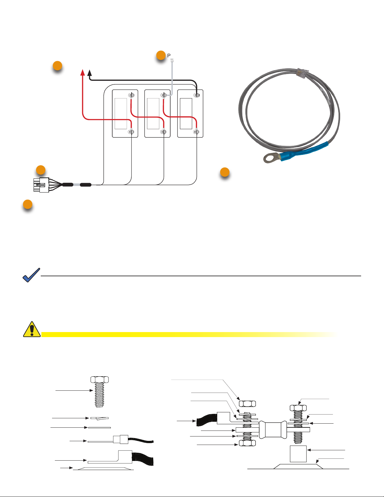
1. Battery Installation and Wiring Diagram
Battery Cable Kit, Precision Temperature Sensor / Smart AlphaGuard or Battery Sense Harness
Load batteries into cabinet with the positive terminals (+) facing forward.
PTS
3
To Power Supply
1
Red
11
Smart AlphaGuard (Embedded) — use Battery Harness, p/n 875-848-20,
11
Black (String -) 0V
36VDC
Black, Pin 5
A/B/C/D NEG
NEG(-) NEG(-) NEG(-)
3A
3A 2A 1A
POS(+)
Red, Pin 9
Vbatt 3A 36V
2A 1A
POS(+) POS(+)
Vbatt 2A 24V
Orange, Pin 4
Vbatt 1A 12V
Brown, Pin 10
Precision Temperature Sensor (PTS), p/n 746-331-20
3
(2 battery strings) — use p/n 875-848-21,
(3 battery strings) — use p/n 875-848-22,
(4 battery strings) — use p/n 875-848-23.
Re-use existing External Alphaguard Battery Sense Harness by installing a retrot kit. External AlphaGuard Battery Sense
Harness to Smart AlphaGuard (1 battery string) — use retrot cable p/n 875-910-20,
(2 battery strings) — use p/n 875-910-21,
(3 battery strings) — use p/n 875-910-22,
(4 battery strings) — use p/n 875-910-23.
NOTE:
The compatibility of the XM3 SAG system with certain vaults is dictated by the length of the SAG harness. Contact
your local sales representative for more information.
Threaded Insert Terminals
CAUTION!
Use 1/4-20 x 3/4” (19mm) bolts for threaded insert terminals. If using a spacer for the in-line fuse link, use 1/4-20 x
1” (25.4mm) bolts.
Torque all nuts and bolts to 110 in-lbs. (12.43N-m)
Nut
3/4" (19mm) x
1/4-20 Bolt
Split Washer
Flat Washer
Battery Sense Cable
or RTS
Battery Cable
Battery Terminal
Split Washer
Flat Washer
Battery
Cable
In-Line Fuse Link
Flat Washer
1" (25.4mm) or
3/4" (19mm) x
1/4-20 Bolt
Fuse
1" (25.4mm) x
1/4-20 Bolt
Split Washer
Flat Washer
Spacer
Battery
Terminal
Page 3

2. Output Voltage Reconguration Procedure
Some systems may require reconguring the output voltage setting. If necessary, follow the steps below to complete the
procedure. If the factory default satises your system requirements, proceed to Section 3.
NOTE:
The output voltage factory default is 89 Volts.
Tools Required:
Small at-blade screwdriver.
1. To access output voltage terminal, remove the Inverter Module.
2. Loosen the terminal screw and move the output voltage wire (Fig. 1)
to the desired output voltage position on the terminal strip.
3. Torque the terminal block screw to 7 in-lbs. (0.79N-m) to secure the
output voltage wire.
4. Replace the Inverter Module.
Fig. 1 - Output voltage wire and terminal bar.
3. DOCSIS Communications Module
Front Panel Connections
1. Connect the Battery Sense Harness to the A/B or C/D Connector (6). For XM3 units with the Smart AlphaGuard
(SAG) option, connect the Battery Harness to the SAG Connector (11) located on the left side of the XM3 Power
Supply.
2. Connect Tamper Switch Wire Harness to the TPR Connector (8).
3. Connect the RF drop to the RF Connector (7).
NOTE:
The DOCSIS specication for downstream power level is 0 dBmV, +/- 15 dBmV. The upstream power level should not
exceed +50 dBmV.
8
TPR Connector
RF Drop
RF Cable
to Headend
To Battery Sense
Harnesses
7
6
Required
Grounded Surge Protector
(Alpha p/n 162-028-10 or equivalent)
Alpha DOCSIS Transponder (1 battery string) — use Battery Sense Harness, p/n 874-842-21.
6
Alpha DOCSIS Transponder (2 battery strings) — use Battery Sense Harness, p/n 874-842-28.
AlphaGuard (external) — use Battery Sense Harness, p/n 875-510-20 (S9) or p/n 875-510-21 (D9).
Page 4

4. Power Module Conguration
Indicates Model
and Output Voltage/Current
Describes Power Supply
Mode of Operation
Describes Status of Functions
Functionality top level menu
PWR, BATT, COMM and APPS
A
B
C
D
A
XM3-918HP 90V/10.0A
B
OPERATION NORMAL
C
OK ALM OK OK
PWR BATT COMM APPS
D
Softkeys (Menu driven
system conguration)
E
E
Installation Procedure
CAUTION!
Before applying power, verify power supply rating is matched to AC input utility. Verify a low-resistance ground is
installed in accordance with the NEC (refer to CableUPS Power Supply technical manual for details).
1. After wiring battery cable kit, battery sense cables and PTS, as shown in
Section 1, verify DC breaker is OFF.
2. Connect the Smart AlphaGuard (SAG) wire harness to SAG port (11). If no
SAG is installed, connect battery sense harness to the transponder (6).
3. Connect PTS to the PTS connector (3).
4. Connect the RF cable and the tamper switch to the transponder.
5. Verify the SPI / ALT Box Switch is in the ALT position.
6. Connect the SPI / ALT Box input cable to the Output 1 Connector (9). If 2nd
SPI / ALT Box is present connect input cable to Output 2 Connector.
7. Connect the LRI to the XM3. For existing LRI installations, use LRI adapter
kit, p/n 875-952-20.
8. Turn ON AC breaker and verify it is the correct utility voltage at the outlet (per
unit’s nameplate voltage). If correct, plug in the line cord into the utility outlet.
9. Verify correct battery voltage and polarity on battery cable connector with a
digital voltmeter, if correct plug into Inverter Module (1).
10. Turn battery breaker ON.
11. Verify no alarms are present after power up initialization. Wait for alarms to
clear (approximately 60 seconds).
12. If no alarms are present, proceed to Step 16.
13. If alarms are present and do not clear after 60 seconds, press the softkey with
ALM (C) to see the ACTIVE ALARM list for the menu item.
14. Press UP (↑) or DOWN (↓) to select the alarm of interest.
15. Press ENTR to select the alarm and display diagnostic information. Press
ESC to return to the alarm list.
16. On the SmartDisplay, press the BATT softkey, enter the BATT CONFIG
menu and select BATT MODEL and NUM BATT STRINGS (Fig. 2).
17. On the SmartDisplay, press BATT softkey, enter BATT CONFIG, enter BATT
MHOs* and DATE Code (Fig. 3).
*Note: Battery MHOs and Date code can only be set after DOCSIS
transponder has registered with CMTS. Please wait 3 minutes after
power up to enter Battery MHOs measurements.
18. Switch SPI / ALT Box Switch to ON, verifying the load on the XM3.
19. Perform a self-test by pressing and holding the Test Button (H) for 1-2
seconds. Wait for self-test completion before proceeding.
20. Perform standby test by shutting OFF utility breaker and verifying it goes into
STANDY MODE and supports the load.
21. Reapply AC power and verify the unit transfers to LINE MODE.
XM3-918HP 90V/0.4A
**ACTIVE ALARM**
OK
PWR
OUTPUT LED (green)
G
SOLID = Operation Normal
FLASHING = Minor Alarm
OFF = Major Alarm
SELF TEST BUTTON
I
Press button to initiate self test.
EDIT USING h i 8 <ESC>
BATT MODEL OTHER
ENTR
BATT A1 DATE 1/10
hi
ENTR to shift eld
ENTR
Fig. 3 - Battery DATE Code and MHOs input
PM
BATT
ALM
COMM
H
h i
Fig. 2 - Battery Model input
ADJUST VALUE
h i
BATT A1 MHOs 1000M
hi
ENTR to save
ENTR
ADJUST VALUE
h i
G
OK
APPS
ALARM LED (red)
FLASHING = Major Alarm
OFF = Minor Alarm
OFF = Operation Normal
ESC
ESC
H
I
ESC
Page 5

5. Alpha DOCSIS Transponder and Smart Alphaguard LED's
5.1 Verify Alpha DOCSIS Transponder operation as indicated below:
LEDs and Indications
Step Communications State ALM/RDY DS REG RF COM
1
2
3
4
Transponder Initializing/Searching for
Downstream DOCSIS channel
DOCSIS Channel locked - Completing
upstream and network registration
Online - Registration Complete Flashing (Green) ON ON
Alpha DOCSIS Transponder fully
functional
LED Color Rx Range (dBmV) Tx Range (dBmV)
Green +10 to -10 0 to +50
* Blue +15 to +10 and -10 to -15 +50 to +55
* Red >+15 and <-15 >+55
* Blue RF LED indicates Rx/Tx Power at a warning level. Make the necessary RF level adjustments.
* Red RF LED indicates Rx/Tx Power at an alert level. Make the necessary RF level adjustments.
NOTE:
Ethernet port LNK and ACT LED’s are on (LNK - Solid, ACT - Flash) only when connected to a laptop.
Flashing (Green) Flashing OFF OFF Flashing
Flashing (Green) ON Flashing
Flashing (Green) ON ON
ON
(Green)
ON
(Green)
ON
(Green)
Flashing
Flashing
Bursts
5.2 Verify Smart AlphaGuard operation as indicated below:
LED State and Indications
LED Name Color State Indication
Off No power to SAG
Unit is on and communicating with power supply or in
Rest mode
Normal operation
No string wires connected
High delta mean
Check battery alarm
String A missing
String miswired
Active Green
STRG A
STRG B
STRG C
STRG D
(ALARMS)
Red
Solid
Flash (90% on / 10% off) Unit is on and operational
Flash (50% on / 50% off) Actively balancing
Flash (10% on / 90% off) Powersave mode
Off
Flash (50% on / 50% off (Minor
Alarm)
Solid (Major Alarm)
5.3 XM3 Smart Display — COMM Menu
COMM-GENERAL
Verify Alpha DOCSIS Transponder communication parameters such as IP Address, RF Power Levels and Signal/
Noise Ratio on the COMM menu of the XM3 Smart Display. Press Enter <ENTR> to open the COMM-GENERAL
Menu enabling the operator to view values for the following parameters. Pressing the up or down arrow softkeys will
show two lines of information for each submenu item.
COMM-GENERAL
CM MAC ADDRESS
00:90:EA:A0:04:99
ESC
Press "Down" arrow softkey to
view next item(s) in menu.
COMM-GENERAL
CM MAC ADDRESS
00:90:EA:A0:04:99
CM IP ADDRESS
192.168.1.121
CM IPV6 ADR PREFIX
2001:123:456:789
CM IPV6 ADR POSTFIX
111:222 :33 3:3 4 3 4
CPE MAC ADDRESS
00:90:EA:00:52:33
Page 6

6.0 Final Verication
Local Web Server Access
The ethernet port of the Alpha DOCSIS Transponder can be used as a local connection point, allowing the user to connect
to the transponder web page.
To access the web page, proceed as outlined below:
NOTE:
A Static IP address (192.168.100.2) may need to be set on your network interface card to connect to the
transponder.
1. Using a standard (CAT5) ethernet cable, connect transponder to the laptop or computer network interface port.
2. Launch a web browser.
3. Enter the transponder’s default IP address (192.168.100.1) into the web browser’s address eld.
4. The transponder’s web server home page will appear.
NOTE:
For the Alpha DOCSIS Transponder, this may take up to 45 seconds when the transponder is initially powered up
with no RF connection.
Remote Web Server Access
To remotely access the Alpha DOCSIS Transponder web server utilizing a web browser:
1. Open a web browser on a computer connected to the same network as the XM3.
2. Enter the Alpha DOCSIS Transponder’s designated IP address (e.g., 192.168.1.124) into the web browser
address eld.
3. The Alpha DOCSIS Transponder ’s web server home page will appear.
Alpha Technologies Inc.
3767 Alpha Way
Bellin gham WA 982 26
USA
Tel: +1 360 647 236 0
Fax: +1 360 671 4936
Alpha Technologies Alpha reserves the right to change specications without notice.
© 2013 Alpha Technologies Inc. All Rights Reserved.
Alpha is a registered trademark of Alpha Technologies. 017-882-B1-001C1 (08/2013) For more information visit www.alpha.com
Alpha Technologies Ltd.
7700 Riverfront Gate
Burnaby BC V5J 5M 4
Canada
Tel: +1 604 436 59 00
Fax: +1 604 4 36 1233
Alpha Technologies Europe Ltd.
Twyford House, Thorley
Bishop’s Stortford,
Hertfordshire
CM22 7PA
United Kingdom
Tel: +44 1279 501110
Fax: +44 1279 659870
Alpha Technologies GmbH
Hansastrasse 8
D 91126 Schwabach
Germany
Tel: +49 9122 7988 9 0
Fax: +49 9122 79 889 21
AlphaTec Ltd.
339 Saint Andrew s Street
Suite 101 Andrea Chambers
3307 Lim assol
Cyprus
Tel: +357 25 375675
Fax: +357 25 3 5959 5
AlphaTEK ooo
Khokh lovskiy Pereulok 16
Stroenie 1 Of ce 403
109028 Moscow
Russia
Tel: +7 495 916 1854
Fax: +7 495 916 1349
Alpha Technologies
Suite 190 3, Tower 1
33 Canton Road, Kowloon
Hong Kong
Tel: +852 2736 8663
Fax: +852 219 9 7988
 Loading...