

Page 1
AlphaNet™ IDH4 Series DOCSIS® Status Monitor
for XM2, XM2-HP, and XM2-300HP Series CableUPS™
Installation and Quick Start Guide
The AlphaNet IDH4 Series Embedded DOCSIS Transponder allows monitoring of Alpha power supplies through existing cable network infrastructure.
Advanced networking services provide quick reporting and access to critical powering information.
The IDH4 Series utilizes Simple Network Management Protocol (SNMP) and standard Management Information Bases (MIBs) to provide network
status monitoring and diagnostics. A Web interface enables authorized personnel direct access to advanced diagnostics using a common Web
browser. No custom software or proprietary cables are required.
The transponders can be installed and congured for operation in the XM2, XM2-HP, or XM2-300HP Power Supply.
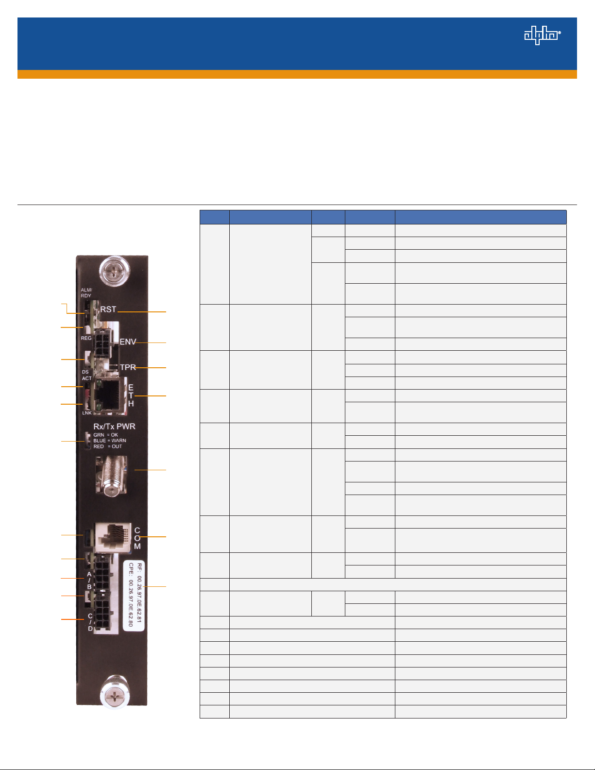
IDH4X DOCSIS Transponder
Item LED or Connector Status Behavior Indication
N/A OFF No power or malfunctioning IDH4 Series
GRN
1 ALM/RDY: Alarm and Ready
RED
1
2
12
2
REG: Upstream ranging and
registration lock
GRN
13
3
14
3
DS: Downstream RF Carrier
detection and lock
GRN
4
15
5
6
4 ACT: CPE Activity status GRN
5 LNK: CPE Link status GRN
16
6
7
17
7
RF Rx/Tx Power Level
Indicator
COM: AlphaBus
communications
TRI
GRN
ON Reset of the IDH4 Series is in process
Steady Blinking Normal operation
Blinking more
OFF than ON
Blinking more
ON than OFF
OFF No power, upstream frequency undetermined
BLINKING
ON CMTS registration completed
OFF No power / downstream carrier
BLINKING Power on, downstream carrier frequency searching
ON Downstream carrier lock
OFF No Ethernet communications activity
BLINKING
OFF No Ethernet link
ON Link on Ethernet Craft port
OFF No RF detected
Blue
Green Rx/Tx RF Power level within tolerance
Red
OFF No AlphaBus Communications
BLINKING Momentary ashes - AlphaBus Port communications active
Minor Alarm
Major Alarm
Power on, downstream locked, upstream frequency ranging,
DHCP request in progress
Momentary ashes during CPE communications via the Ethernet
craft port
Rx/Tx Power at a warning level as set within the SCTE-HMS
Property Table
Rx/Tx Power at an alert level as set within the SCTE-HMS
Property Table
8
9
10
11
746-257-B0-001 Rev. A (2/2014)
ON Battery string(s) connected correctly
OFF Battery string(s) not connected correctly
ON Battery string(s) connected correctly
OFF Battery string(s) not connected correctly
18
8 BAT A/B GRN
9 BAT A/B Connector
10 BAT C/D GRN
11 BAT C/D Connector
12 RST: Reset buttton
13 ENV: Environmental Control connector
14 TPR: Tamper Switch connector
15 ETH: Ethernet connection
16 RF Connection
17 COM: AlphaBus Communications connector
18 RF, CPE MAC Address label
Fig. 1, IDH4X Transponder Front Panel Indicators and Connectors
1
Page 2
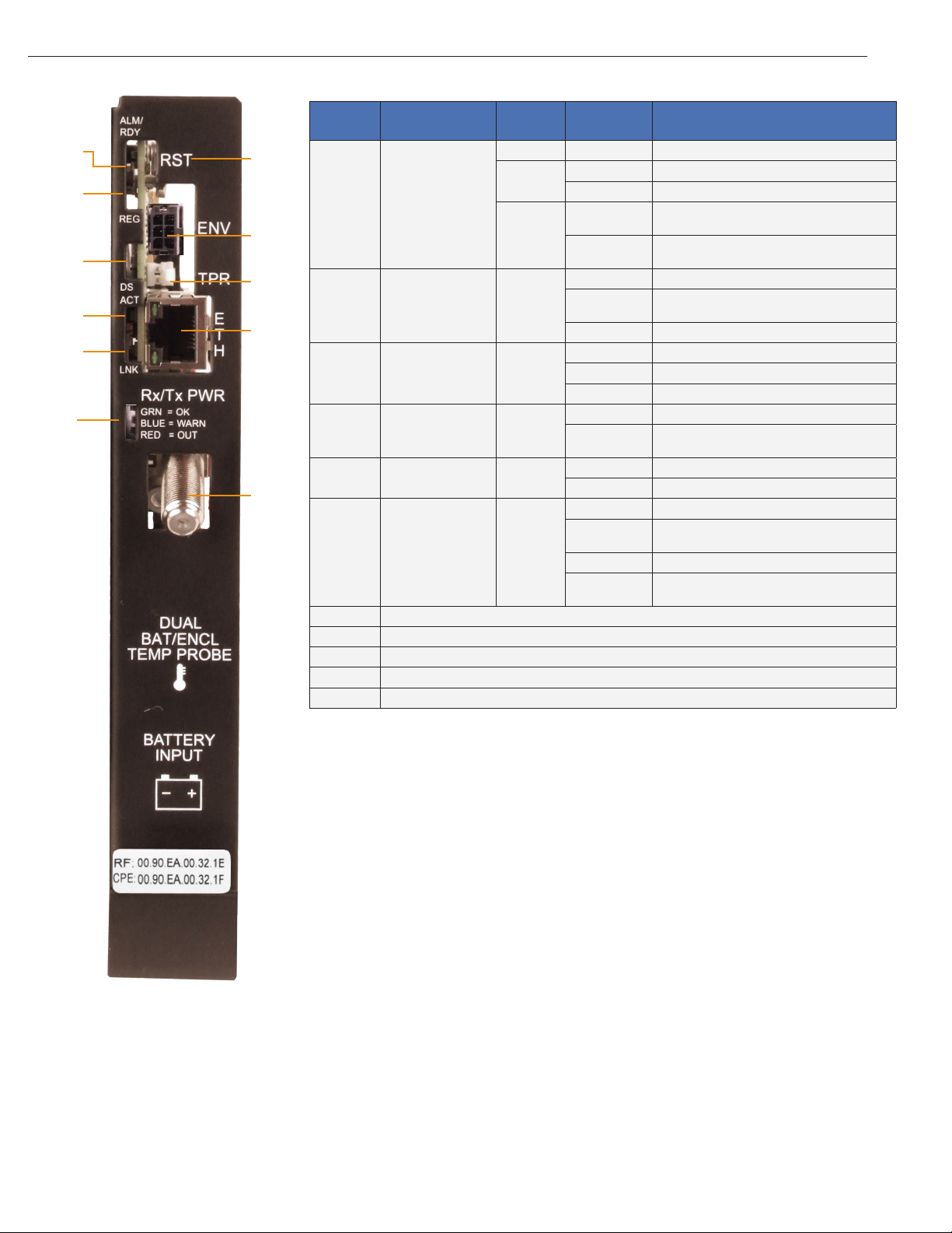
IDH4L DOCSIS Transponder
Item
1
2
7
1
8
3
9
4
2
10
5
3
6
4 ACT: CPE Activity status GRN
5 LNK: CPE Link status GRN
11
6
7 RST: Reset buttton
8 ENV: Environmental Control connector
9 TPR: Tamper Switch connector
10 ETH: Ethernet connection
11 RF Connection
LED or
Connector
ALM/RDY: Alarm and
Ready
REG: Upstream ranging
and registration lock
DS: Downstream RF
Carrier detection and
lock.
RF Rx/Tx Power Level
Indicator
Status Behavior Indication
N/A OFF No power or malfunctioning transponder
GRN
RED
GRN
GRN
TRI
ON Transponder reset in process
Steady Blinking Normal operation
Blinking more OFF
than ON
Blinking more ON
than OFF
OFF No power, upstream frequency undetermined
BLINKING
ON CMTS registration completed
OFF No power / downstream carrier
BLINKING Power on, downstream carrier frequency searching
ON Downstream carrier lock
OFF No Ethernet communications activity
BLINKING
OFF No link
ON Link on Ethernet Craft port
OFF No RF detected
Blue
Green Rx/Tx RF Power level within tolerance
Red
Minor Alarm
Major Alarm
Power on, downstream locked, upstream frequency
ranging, DHCP request pending
Momentary ashes during CPE communications via the
Ethernet Craft port
Rx/Tx Power at a warning level as set within the SCTEHMS Property Table
Rx/Tx Power at an alert level as set within the SCTE-HMS
Property Table
Fig. 2, IDH4L Transponder Front Panel Indicators and Connectors
2746-257-B0-001 Rev. A (2/2014)
Page 3

Overview
CAUTION!
For units in service, backup battery power will not be available during this procedure.
IDH4 Series installation and setup is comprised of three basic steps:
1. Conguring the Network: Provisioning the DHCP Server with the transponder’s MAC Address and assigning it a
DOCSIS Conguration File.
2. Setting Options: The IDH4 Series is designed for out-of-the-box, "plug and play" operation, but non-default settings
such as SNMP trap destination addresses may be required for the Network Management System (NMS). SNMP trap
addresses can be set automatically via the DOCSIS Conguration File per RFC 4639, while IDH4 Series proprietary
options may be set through type-11 TLV entries. The SCTE-HMS and Alpha MIBs may need to be compiled into a MIB
browser before it can be used to monitor or set transponder and power supply parameters. Refer to the IDH4 for XM2
and XM2-HP Technical Manual (Alpha p/n 746-257-B2-001) for details.
3. Installation: Installation of the IDH4 Series into the power supply, connecting the RF Cable, battery sense wire harnesses
(IDH4X only), Environmental, Tamper switch, Ethernet, and verifying operation.
These steps can be performed independently of one another. However, conguring the network prior to eld installation will
allow the installation to be veried while personnel are still on-site. Performing eld installation before network conguration
and before the installation can be veried, might result in additional eld service calls to correct mistakes.
IDH4X Installation / Replacement Procedure in XM2 and XM2-HP Power
Supplies
1. Before removing the Inverter Module (IM), verify the power supply device address is correct.
The power supply device address must not be set to zero and no two power supplies monitored by a single IDH4 Series
can have the same address. Power supplies must have 1, 2, 3, 4 or 5 as an address.
To verify the power supply’s address, go to the LCD display on the inverter module and enter the "Setup" menu. Scroll
to the "Device Address" menu item and verify the device address is set to something other than 0 (Zero).
2. Switch OFF the power supply’s battery breaker.
NOTE:
With the battery breaker in the OFF position, the power supply will not go into inverter mode.
3. Unplug all Inverter Module connections (e.g. battery cable, remote temperature sensor).
4. Loosen the Inverter Module thumbscrews and slide the inverter module out just enough to disconnect the ribbon cable.
Disconnect the ribbon cable.
5. Slide the Inverter Module out of the power supply.
3746-257-B0-001 Rev. A (2/2014)
Page 4

IDH4X Installation / Replacement Procedure in XM2 and XM2-HP Power Supplies,
continued
6. If the Inverter Module is equipped with a communication module, remove it by loosening the two Phillips captive screws.
7. Plug the supplied 18-pin jumper into the header on the back of the IDH4 Series circuit board.
Disconnect here
Captive Screws
Fig. 3, Inverter Module Ribbon Cable
Fig. 4, Captive Screw Locations
NOTE:
To prevent damage to the IDH4X, do not reuse the existing 18-pin connector. Instead, use the jumper supplied with the
transponder.
Fig. 5, Installing 18-pin Jumper
(Alpha p/n 540-286-19)
Fig. 6, Connecting the Transponder to the Inverter Module
8. Line up the 18-pin jumper with the header on the Inverter Module and connect the unit to the Inverter Module.
9. Fasten the IDH4 Series to the Inverter Module by tightening the two captive screws. It is recommended that the screws
be tightened alternately, a few turns at a time so the transponder aligns in parallel to the Inverter Module.
10. Reinstall the Inverter Module and reconnect the ribbon cable. Make front panel connections (tamper, temperature sensor,
battery sense, RF etc.).
11. If not yet done, record the cable modem MAC address from the front of the unit and report it to the network manager for
network provisioning. For Dual IP applications, the CPE MAC address should also be recorded.
4746-257-B0-001 Rev. A (2/2014)
Page 5

IDH4L Installation / Replacement Procedure in XM2-300HP Power Supplies
1. Before removing the Inverter Module (IM), verify the power supply device address is correct.
The power supply device address must not be set to zero and no two power supplies monitored by a single IDH4 Series
can have the same address. Power supplies must have 1, 2, 3, 4 or 5 as an address.
To verify the power supply’s address, go to the LCD display on the inverter module and enter the "Setup" menu. Scroll
to the "Device Address" menu item and verify the device address is set to something other than 0 (Zero).
2. Switch OFF the power supply’s battery breaker.
NOTE:
With the battery breaker in the OFF position, the power supply will not go into inverter mode.
3. Unplug all Inverter Module connections (e.g. battery cable, remote temperature sensor).
Inverter Module
Thumbscrews
Fig. 7, Removing the Inverter Module from the Power Supply
4. Loosen the Inverter Module thumbscrews.
5. Slide the Inverter Module out of the power supply.
6. Loosen the two Phillips captive screws to remove the IDH4L sheet metal from the Inverter Module.
Power Supply
Battery Breaker
Captive Screw
Captive Screw
Fig. 8, Removing the IDH4L Sheet Metal from the Inverter Module
5746-257-B0-001 Rev. A (2/2014)
Page 6

IDH4L Installation / Replacement Procedure in XM2-300HP Power Supplies, continued
7. Plug the supplied 18-pin jumper into the header on the Inverter Module.
NOTE:
To prevent damage to the IDH4L, do not reuse the existing 18-pin connector. Instead, use the jumper supplied with
the transponder.
Fig. 9, Installing 18-pin Jumper
(Alpha p/n 540-581-19)
8. Attach the IDH4L to the sheet metal with the supplied 6-32 screws.
9. Line up the 18-pin jumper with the header on the Inverter Module and connect the unit to the inverter module.
Fig. 10, IDH4L Attached to Sheet Metal
10. Fasten the IDH4L to the Inverter Module by tightening the two captive screws. It is recommended that the screws be
tightened alternately, a few turns at a time so the transponder aligns in parallel to the Inverter Module.
11. Reinstall the Inverter Module and make front panel connections (tamper, temperature sensor, battery, RF, etc.).
12. If not yet done, record the cable modem MAC address from the front of the unit and report it to the network manager
for network provisioning. For Dual IP applications, the CPE MAC address should also be recorded.
Fig. 11, IDH4L Inverter Module Connection
6746-257-B0-001 Rev. A (2/2014)
Page 7

Connecting the RF Drop
CAUTION!
Install a grounded surge suppressor (Alpha P/N 162-028-10 or equivalent).
Connect the RF drop according to the diagram below. The RF drop must have a properly installed ground block in the
power supply enclosure. Recommended downstream RF level is 0 dBmV. Connect any other front panel connections at
this time (e.g. battery strings, tamper switch).
Grounded Surge Protector
(See Caution Above)
RF Cable
to Headend
Fig. 13, Connecting the RF Drop
ECM to SCM Interface
(Alpha P/N 704-709-20)
Linked CableUPS
Serial Interface Cards
B
S
Y
S
C
O
M
A
Comm Port
A
B
System Port
C
Battery Sense Connections
A
S
Y
S
C
O
M
IDH4X in
Primary XM2
B
A
C
AlphaBus Cable
(Alpha P/N 875-190-20 for 6',
-21 for 9', -22 for 18', -23 for 35')
Environmental
connection
Ethernet connection
RF connection
Generator (ECM)
Battery Sense Wire Harness
Connections
Connections with
more than one power
supply
Fig. 14, System Interconnection Diagram
NOTE:
Each power supply must have a unique address. Refer to Intelligent CableUPS technical manual
(Alpha p/n 017-805-B0), or the IDH4 Series Transponder Technical Manual (Alpha p/n 746-257-B2) for
additional information.
7746-257-B0-001 Rev. A (2/2014)
Page 8

Total Power Solutions
Initial Startup and Test / Returning the Unit to Service
1. Plug the power supply into the AC outlet.
2. Switch battery breaker ON.
3. The IDH4 Status LEDs will all blink in unison upon initial power up. The RDY LED will then begin blinking steadily indicating
normal processor activity.
4. Verify the DS and REG LEDs are on solid. This veries the Communications Module has registered an IP address on the
network.
5. Verify the RF LED is solid Green, indicating Upstream and Downstream Power is within the default specied range and the
Upstream RF Power is below the recommended +50 dBmV.
6. Verify no XM2 / XM2-HP / XM2-300HP alarms are active.
RF Power Default Values
LED Color Rx Range (dBmV) Tx Range (dBmV)
Green +10 to -10 0 to +50
Blue +15 to +10 and -10 to -15 +50 to +55
Red >+15 and <-15 >+55
Table 1, RF Power Default Values
Test Connection
With the IDH4 Series Transponder used in conjunction with the XM2-HP power supply, network connectivity can be veried via
the smart display. For other power supply models, verify the network status via the Ethernet port.
Connect a computer’s network port to the transponder’s Ethernet port using a standard network cable. Launch an Internet
browser and enter 192.168.100.1 into the Address. The transponder will return the Web page shown below. The General
Conguration page shown below will appear and display connectivity, power levels, and power supply status information such as
alarms, output voltage, output current, and individual battery voltages. System Name, System Location, System Contact and
Common Logical ID may be edited on this page; when prompted for a User Name and Password, use "Alpha" and "AlphaGet".
Alpha Technologies Inc.
3767 Alpha Way
Bellingham WA 98226
USA
Tel: +1 360 647 236 0
Fax: +1 360 671 493 6
Alpha Technologies
Alpha Technologies Ltd.
7700 Riverfront Gate
Burnaby BC V5J 5M4
Canada
Tel: +1 604 436 5900
Fax: +1 604 4 36 1233
Alpha re serves the r ight to change specicat ions without n otice.
© 2014 Alpha Technologies Inc. All Rights Reserved.
Alpha is a registered t rademark of A lpha Technologi es. 746-257-B0-001 Rev. A (2/2014) For more information visit www.alpha.com
(data values shown for illustration purposes only)
Alpha Technologies Europe Ltd.
Twyford House, Thorley
Bishop’s Stortford,
Hertfordshire
CM22 7PA
United Kingdom
Tel: +44 1279 501110
Fax: +44 1279 659870
Fig. 15, Initial Web Page
Alpha Technologies GmbH
Hansastrasse 8
D 91126 Schwabach
Germany
Tel: +49 9122 79889 0
Fax: +49 9122 7 9889 21
Al phaTe c Lt d.
339 Sai nt Andrews Str eet
Suite 101 Andrea Chambers
3307 Limassol
Cyprus
Tel: +357 25 375675
Fax: +357 25 359595
AlphaTEK ooo
Khokhlovskiy Pereulok 16
Stroenie 1 Ofce 4 03
109028 Moscow
Russia
Tel: +7 495 916 1854
Fax: +7 495 916 1349
member of The Group
Alpha Technologies
Suite 190 3, Tower 1
33 Canton Road, Kowloon
Hong Kong, China
Tel: +852 2736 8 663
Fax: +852 2199 7988
TM
 Loading...