

Page 1
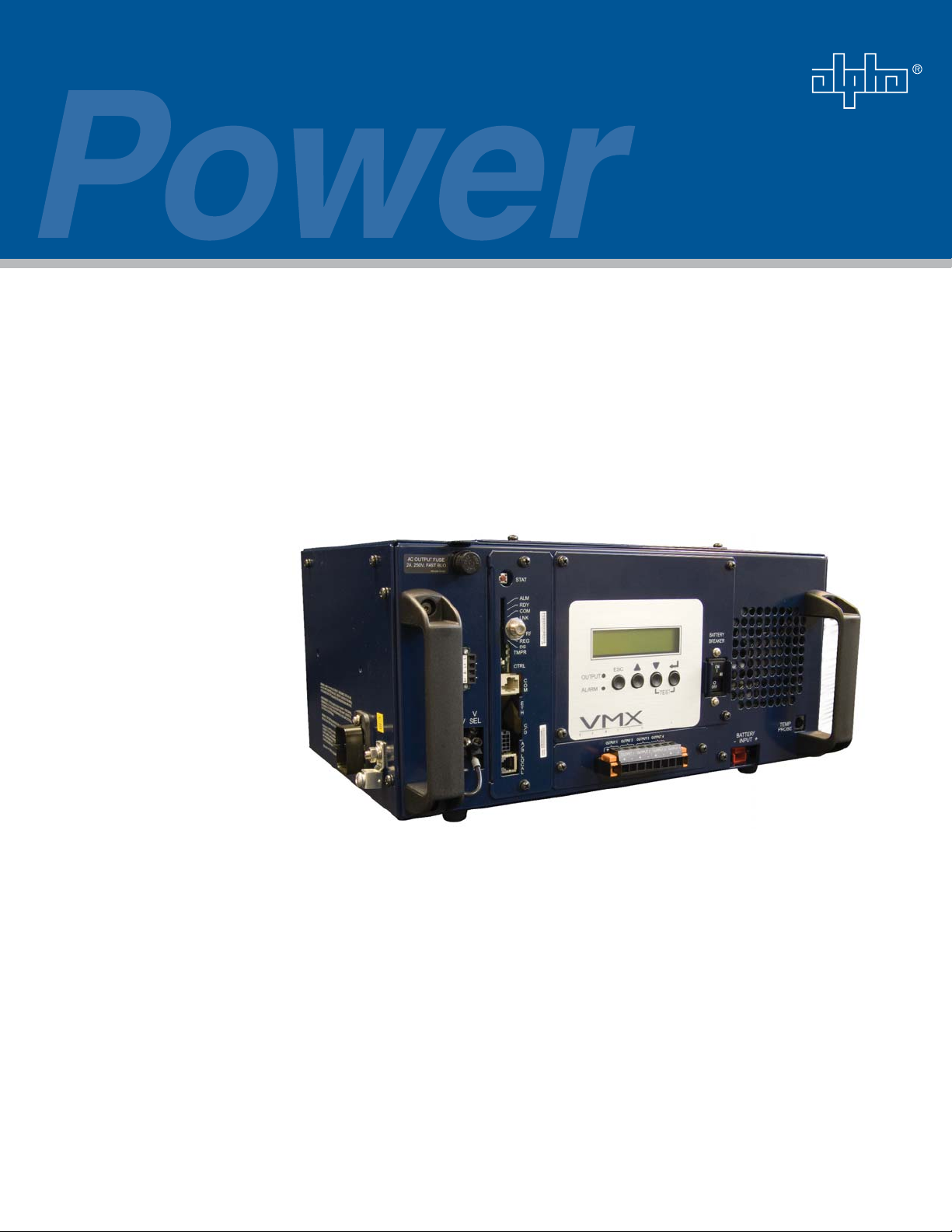
VMX
Standby Power Supply
Technical Manual
VMX Series Standby Power Supply
Effective: October, 2007
Alpha Technologies
Page 2

Alpha Technologies
Power
®
Page 3
VMX Standby Power Supply
017-940-B0-001, Rev A
Effective Date: October, 2007
Copyright© 2007
Alpha Technologies, Inc.
member of The Group
NOTE:
Photographs contained in this manual are for illustrative purposes only. These photographs may not match
your installation.
NOTE:
Operator is cautioned to review the drawings and illustrations contained in this manual before proceeding. If
there are questions regarding the safe operation of this powering system, please contact Alpha Technologies
or your nearest Alpha representative.
NOTE:
Alpha shall not be held liable for any damage or injury involving its enclosures, power supplies, generators,
batteries, or other hardware if used or operated in any manner or subject to any condition not consistent with
its intended purpose, or is installed or operated in an unapproved manner, or improperly maintained.
Notice of FCC Compliance
Per FCC 47 CFR 15.21:
Changes or modifi cations not expressly approved by the party responsible for compliance could void the user’s authority to operate the
equipment.
Per FCC 47 CFR 15.105:
This equipment has been tested and found to comply with the limits for a Class A digital device, pursuant to part 15 of the FCC Rules.
These limits are designed to provide reasonable protection against harmful interference when the equipment is operated in a commercial
environment. This equipment generates, uses, and can radiate radio frequency energy and, if not installed and used in accordance with the
instruction manual, may cause harmful interference to radio communications. Operation of this equipment in a residential area is likely to
cause harmful interference in which case the user will be required to correct the interference at their own expense.
TM
Contact Alpha T echnologies: www.alpha.com
or
For customer service (7 AM to 5 PM, Pacifi c Time), call:
For complete technical support, call: 1-800-863-3364
7 AM to 5 PM, Pacifi c Time, or 24/7 emergency support
In the UK call: +44 0 1279 501110
In Germany call: +49 9122 79889 0
To report errors in this document, send an email to:
1-800-863-3930
3
Page 4

Table of Contents
Safety Notes .......................................................................................................................... 7
Utility Power Connection Notes .................................................................................. 9
Signal Ground ............................................................................................................11
1.0 Introduction to the VMX Power Supply ..................................................................... 12
1.1 Connections Overview ................................................................................... 13
1.2 Inverter Overview ...........................................................................................14
1.3 Optional Status Monitoring Modules .............................................................. 15
1.4 Optional Features .......................................................................................... 16
2.0 Theory of Operation ..................................................................................................17
2.1 AC (Line) Operation ....................................................................................... 17
2.2 Standby Operation ......................................................................................... 17
2.3 Charger Operation ......................................................................................... 18
3.0 Installation.................................................................................................................20
3.1 Installation Procedure .................................................................................... 21
3.2 Service Power Inserter Connections.............................................................. 22
3.3 Installing the Coax Cable Connector Outputs ................................................25
4.0 Confi guration ............................................................................................................26
4.1 Micro Board Setup ......................................................................................... 26
4.2 AC Output Voltage Reconfi guration ...............................................................27
5.0 Operation ..................................................................................................................28
5.1 Start-up and Test ............................................................................................28
5.2 Smart Display ................................................................................................. 31
5.2.1 Operation Normal ................................................................................ 33
5.2.2 Additional Information Display............................................................. 34
5.2.3 Setup Menu ......................................................................................... 35
5.2.4 Alarm Indications................................................................................. 38
5.2.5 Control Panel LEDs............................................................................. 40
5.2.6 Detailed Menu Structure and Navigation ............................................ 41
5.3 Smart Display Glossary .................................................................................43
5.4 Automatic Performance Test .......................................................................... 45
4
017-940-B0-001, Rev. A
Page 5

5.5 Providing Power via External Source............................................................. 46
5.5.1 DC Powering ....................................................................................... 46
5.5.2 AC Powering ....................................................................................... 46
5.5.3 Using a Truck-mounted Inverter or Generator .................................... 47
5.6 Resumption of Utility Power ...........................................................................48
6.0 VMX Power Supply Maintenance ............................................................................. 49
6.1 Check Battery Open Circuit Voltage .............................................................. 49
6.2 System Information ........................................................................................ 49
6.3 Check Battery Voltage Under Load................................................................ 50
6.4 Check Battery Charger Voltage ..................................................................... 51
6.5 Check Battery Terminals and Connecting Wires ............................................ 51
6.6 Check Output Voltage .................................................................................... 51
6.7 Check Output Current .................................................................................... 51
6.8 Replacing the Metal Oxide Varistors ..............................................................52
6.9 Maintenance Log ...........................................................................................53
7.0 Specifi cations............................................................................................................54
7.1 Safety and EMC Compliance .........................................................................55
8.0 Troubleshooting ........................................................................................................ 56
8.1 Return/Repair Information.............................................................................. 56
8.2 Parts Ordering Instructions ............................................................................56
8.3 Emergency Shutdown .................................................................................... 57
017-940-B0-001, Rev. A
5
Page 6

List of Figures and Tables
Fig. 1-1, VMX Power Supply ............................................................................................... 12
Fig. 1-2, VMX Terminal Block Overview .............................................................................. 13
Fig. 1-3, Inverter Overview .................................................................................................. 14
Fig. 2-1, Charger Modes...................................................................................................... 18
Fig. 2-2, VMX Block Diagram .............................................................................................. 19
Fig. 3-1, SPI Cover Removal ...............................................................................................22
Fig. 3-2, Coaxial Cable Insertion and Securing ................................................................... 22
Fig. 3-3, Cover Replaced, SPI Switched On ....................................................................... 23
Fig. 3-4, SPI Grounding Lug ................................................................................................23
Fig. 3-5, Enclosure Ground Bar ...........................................................................................23
Fig. 3-6, Wire/Connector Assembly .....................................................................................23
Fig. 3-7, SPI to Output 1-4 Connection ............................................................................... 24
Fig. 4-1, Micro Board Settings ............................................................................................. 26
Fig. 4-2, Transformer Output Tap Connector ....................................................................... 27
Fig. 5-1, Confi guration Screen............................................................................................. 28
Fig. 5-2, Smart Display ........................................................................................................31
Fig. 5-3, Additional Info Display ...........................................................................................34
Fig. 5-4, Setup Menu Display .............................................................................................. 37
Fig. 5-5, Smart Display LEDs .............................................................................................. 40
Fig. 6-1, MOV Removal ....................................................................................................... 52
Fig. 6-2, MOV Replacement ................................................................................................ 52
Table 5-1, Setup Menu Parameters ..................................................................................... 36
Table 5-2, Major Alarms ....................................................................................................... 39
Table 5-3, Minor Alarms ....................................................................................................... 39
6
017-940-B0-001, Rev. A
Page 7
Safety Notes
Review the drawings and illustrations contained in this manual before proceeding. If there are any questions
regarding the safe installation or operation of this product, contact Alpha Technologies or the nearest Alpha
representative. Save this document for future reference.
To reduce the risk of injury or death, and to ensure the continued safe operation of this product, the following
symbols have been placed throughout this manual. Where these symbols appear, use extra care and
attention.
ATTENTION:
The use of ATTENTION indicates specifi c regulatory/code requirements that may affect the placement of
equipment and /or installation procedures.
NOTE:
A NOTE provide additional information to help complete a specifi c task or procedure.
CAUTION!
The use of CAUTION indicates safety information intended to PREVENT DAMAGE to material or
equipment.
WARNING!
WARNING presents safety information to PREVENT INJURY OR DEATH to the technician
or user.
Safety Precautions
• Only qualifi ed personnel may service the VMX Power Supply.
• The VMX shall be installed in an appropriate enclosure in accordance with the requirements of IEC
60364-4-482.
• Verify the voltage requirements of the equipment to be protected (load), the AC input voltage to the power
supply (line), and the output voltage of the system prior to installation.
• Equip the utility service panel with a properly rated circuit breaker for use with this power supply.
• When connecting the load, DO NOT exceed the output rating of the power supply.
• Always use proper lifting techniques whenever handling the power supply or batteries.
• The VMX Power Supply contains more than one live circuit! Even though AC voltage is not present at the
input, voltage may still be present at the output.
• If batteries are being stored prior to installation, charge at least once every three months to ensure
optimum performance and maximum battery service life.
• To reduce the chance of spark, and wear on the connectors, always switch the inverter’s battery circuit
breaker off before connecting or disconnecting the battery pack.
• The battery pack, which provides backup power, contains dangerous voltages. Only qualifi ed personnel
should inspect or replace batteries.
• In the event of a short circuit, batteries present a risk of electrical shock and burns from high current.
Observe proper safety precautions.
• Always wear protective clothing, insulated gloves and eye protection (safety glasses or face shield)
whenever working with batteries.
017-940-B0-001, Rev. A
7
Page 8

Safety Precautions, continued
• Do not allow live battery wires to contact the enclosure chassis. Shorting battery wires can result in a fi re
or possible explosion.
• Always replace batteries with those of an identical type and rating. Never install old or untested batteries.
• Avoid using uninsulated tools or other conductive materials when handling batteries or working inside the
enclosure.
• Remove all rings, watches and other jewelry before servicing batteries.
• Spent or damaged batteries are environmentally unsafe. Always recycle used batteries. Refer to local
codes for proper disposal of batteries.
Battery Safety Notes
• Always refer to the battery manufacturer’s recommendation for selecting correct “FLOAT” and “ACCEPT”
charge voltages. Failure to do so can damage the batteries.
• Verify the VMX battery charger's “FLOAT” and “ACCEPT” voltage settings. See Section 5.2.3, Setup
Menu.
• Batteries are temperature sensitive. During extremely cold conditions, a battery’s charge acceptance
is reduced and requires a higher charge voltage. During extremely hot conditions, a battery’s charge
acceptance is increased and requires a lower charge voltage. To compensate for changes in temperature,
the battery charger is temperature compensating.
• If the batteries appear to be overcharged or undercharged, fi rst check for defective batteries and then
verify the correct charger voltage settings.
• To ensure optimum performance, inspect batteries every three to six months for signs of cracking,
leaking, or unusual swelling (note that some swelling is normal).
• Check battery terminals and connecting wires. Clean battery terminal connectors periodically and torque
to manufacturer's specifi cations. Spray the terminals with an approved battery terminal coating such as
NCP-2.
NOTE:
If installed, disconnect the AlphaGuard (AG-CMT) prior to measuring battery voltage.
NOTE:
Even with a AG-CMT present in the system, any battery which fails the 0.3V load test must be replaced with
an identical type of battery.
• Check battery voltages UNDER LOAD. Use a load tester if available. Differences between any battery in
the set should not be greater than 0.3Vdc.
• Refer to the battery manufacturer’s recommendation for correct charger voltages.
• Number the batteries (1, 2, 3, etc.) inside the enclosure for easy identifi cation (refer to the appropriate
enclosure installation guide).
• Establish and maintain a battery maintenance log (see Section 6.9).
NOTE:
Always verify proper polarity of cables before connecting the batteries to the power module. The batteries are
clearly marked for polarity. If the cables become interchanged at the batteries the battery breaker will trip.
8
017-940-B0-001, Rev. A
Page 9
Utility Power Connection Notes
ATTENTION:
Connecting to the utility should be performed only by qualifi ed service personnel and in compliance with local
electrical codes. Connection to utility power must be approved by the local utility before installing the power
supply.
ATTENTION:
UL and NEC require that a service disconnect switch (UL listed) be provided by the installer and be connected
between the power source and the VMX Power Supply. Connection to the power supply must include an
appropriate service entrance weather head.
NOTE:
In order to accommodate the high-inrush currents normally associated with the start-up of ferroresonant
transformers (400A, no-trip, fi rst-half cycle), either a “high-magnetic” or HACR (Heating, Air Conditioning,
Refrigeration) trip breaker must be used. Do not replace these breakers with a conventional service entrance
breaker. Alpha recommends ONLY Square D breakers because of increased reliability in this powering
application. High-magnetic Square D circuit breakers and BBX option (UL Listed service entrance) are
available from Alpha Technologies.
Description Alpha P/N Square D Part Number
230V Installation — HACR (15A) 470-224-10 QO215
BBX — External Service Disconnect 020-085-10 QO2-4L70RB
BBX — External Service Disconnect 020-141-10 QO8-16L100RB
VMX Line Cord Options Alpha P/N
Line Cord,3C, #14, SCHUKO/320 C19 RECT, 1M (EU) 875-432-10
Line Cord, 3C, #14, SCHUKO/IEC 320 C19 REPT, 2.5M (EU) 875-433-10
Line Cord,3C, #14, BS546/IEC 320 C19 RCPT, 1M (India) 875-434-10
Line Cord,3C, #14, BS1363/IEC 320 C19 RCPT, 2M (UK) 875-435-10
Line Cord,3C, CHN/IEC 320 C19 RCPT, 1M (China) 875-436-10
Line Cord, 3-conductor, 12AWG, NEMA 6-15P (US) 875-471-10
017-940-B0-001, Rev. A
9
Page 10
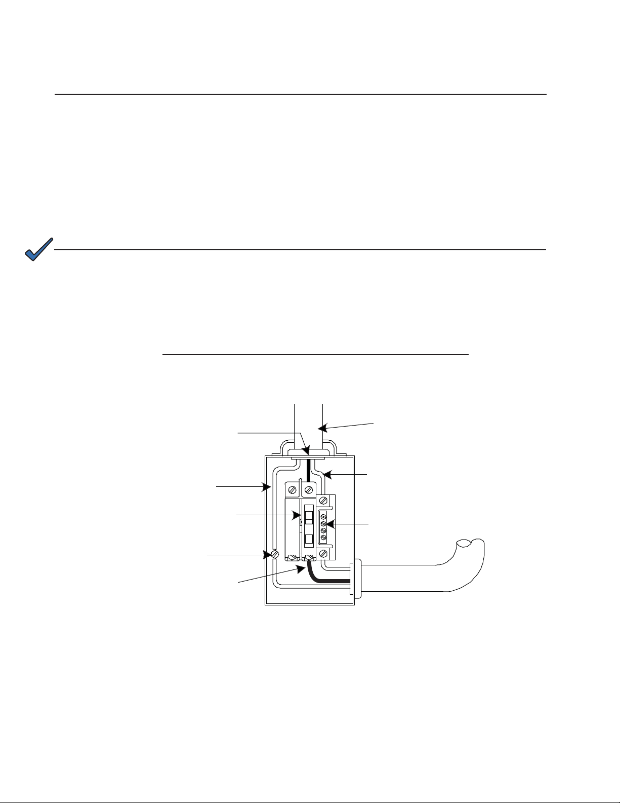
Utility Power Connection Notes
ATTENTION:
In most cases, the following confi gurations qualify for service entrance use when wiring a duplex receptacle
to a service disconnect. Other codes may also apply. Always contact your local utility to verify that the wiring
conforms to applicable codes.
240Vac Service Entrance, VMX 225V, U.S. Domestic Models
These confi gurations are equipped with a 240Vac duplex receptacle to provide power to the power supply
and peripheral equipment. The receptacle, NEMA 6-15R, is protected by a single, 2-pole, common trip 15A
circuit breaker located inside the service entrance. Wiring is typical 14AWG per NEC code, and a grounding
clamp, located on the enclosure, facilitates dedicated grounding.
NOTE:
To bond the box to a neutral plate, use the long green bonding screw provided (Alpha P/N 523-011-10).
220, 230, 240Vac Service Entrance, VMX 225V, International Models
Typical 220, 230, 240Vac 15A Service Entrance Wiring, International
Line (Black)
Copper Ground Wire
#8 AWG (Minimum)
Breaker
Grounding Point Made
to Enclosure Wall
To Utility
Neutral (White)
Neutral Bus
LI
10
017-940-B0-001, Rev. A
Page 11

Grounding Connection Notes
In order to provide a ready, reliable, source of backup power, it is necessary to establish a grounding system
that provides for the safety of service personnel and for the proper operation and protection of equipment
within the network.
Safety Ground
The safety ground is a two-part system. The fi rst part is a return path for stray current back to the input
breaker, and the second is a return path from the Alpha enclosure to a second ground rod.
Typically, the utility ground provides a return path to the input breaker or fuse panel by means of a connection
to an appropriate driven ground rod at the base of the power pole. This path must meet all local and national
standards and regulations.
The second part of the safety ground arrangement is the ground path between the Alpha enclosure and a
second ground rod located at least six feet away from the driven ground rod at the power pole. The second
ground rod and enclosure are connected via #6AWG solid copper wire buried at a depth of 8 to 12 inches. The
wire is connected to a ground lug on the back of the cabinet (for pole-mounted enclosures), or to a ground
lug inside the cabinet (for ground-mounted enclosures). Connection to the ground rod is made with a listed
grounding clamp suitable for direct burial, or by exothermic weld. Normally it is specifi ed that the impedance of
this ground can be no greater than 25 ohms at 60Hz. However, if dual ground rods are installed approximately
eight feet apart, it is not necessary to measure the impedance of the ground rods (it is assumed that the
impedance specifi cation is met).
Signal Ground
For proper operation, the Service Power Inserter (SPI) must be securely grounded to the enclosure chassis.
For systems utilizing ESM/DSM status monitoring, the coax drop ground connection is made through a
separate chassis ground block (Alpha P/N 162-028-10).
Strike (Lightning) Ground
Lightning strikes, grid switching, or other aberrations on the power line all have the potential to cause “fast
rise-time currents” that can cause damage to the powering system. Without a low-impedance path to ground,
the current, while traveling through wires of varying impedance, can produce high voltages that will damage
the powering equipment. The most viable method available to protect the system from damage is to divert
these unwanted fast rise-time currents along a low-impedance path to ground. A low-impedance path to
ground will prevent these currents from reaching high voltage levels and posing a threat to equipment. The
single-point grounding system provides a low-impedance path to ground, and the key to its success is the
proper bonding of the ground rods, so the components of the grounding system appear as a single point of
uniform impedance.
WARNING!
Low impedance grounding is mandatory for personnel safety and critical for the proper
operation of the cable system.
017-940-B0-001, Rev. A
11
Page 12
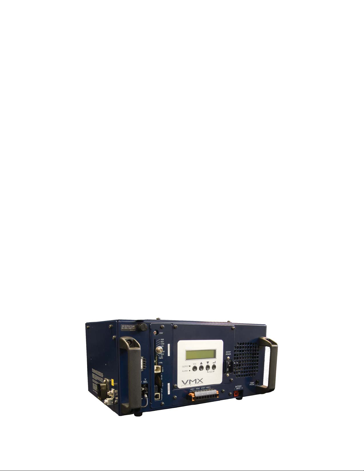
1.0 Introduction to the VMX Power Supply
The Alpha family of VMX Uninterruptible Power Supplies is designed for powering signal processing
equipment in cable television and broadband LAN distribution systems. The VMX provides a critical
load with current-limited, regulated, AC power that is free of spikes, surges, sags and noise.
During AC line operation, AC power entering the power supply is converted into a quasi square wave
and is regulated by a ferroresonant transformer at the required output voltage. The regulated voltage
is connected to the load via the O
to the battery charger to maintain a fl oat charge on the batteries.
When the incoming AC line voltage signifi cantly deviates from normal, the VMX Power Supply
automatically switches from the AC line to Standby mode, maintaining power to the load. During the
switch to standby operation, energy in the module’s ferroresonant transformer continues to supply
power to the load. While in Standby mode, the VMX powers the load until the battery voltage reaches
a low-battery cutoff point.
When utility power returns, the VMX Power Supply waits a short time (approximately 10 to 20
seconds) for the utility voltage and frequency to stabilize, and then initiates a smooth, in-phase
transfer back to AC line power. Once the transfer is complete, the battery charger recharges the
batteries in preparation for the next event.
Key components of the VMX Power Supply include a line-conditioning ferroresonant transformer,
resonant capacitor, transfer isolation relay, and inverter. The inverter contains circuitry for the threestage temperature-compensated battery charger, DC to AC converter (inverter), AC line detector, and
Smart Display. An optional communciation module provides remote status monitoring.
UTPUT 1-4 ± terminal block connections, and some power is directed
The VMX Power Supply features:
• Line Interactive Ferro Technology (LIFT)
• Smart Display
• Built-in programmable battery self-test
• 3-stage temperature compensated battery charger
• Automatic battery detection
• Field programmable fl ash memory
• Four-Output Protection Interface Module
• Digital status monitoring (optional)
12
Fig. 1-1, VMX Power Supply
017-940-B0-001, Rev. A
Page 13
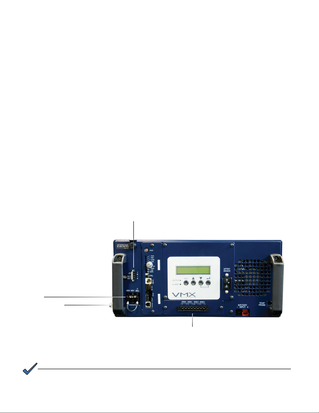
1.0 Introduction to the VMX Power Supply, continued
1.1 Connections Overview
Below is a brief description of each terminal.
Connections:
• AUX OUT (Auxiliary Output): The Auxiliary Output is an uninterruptible supply of power
that can be used to power external devices such as cable modems or ethernet hubs. The
auxiliary output is rated at 220V 150W and uses a 2A 250V fast blow fuse (Alpha P/N
460-157-19).
• LRI (Local/Remote Indicator): The LRI lamp option connects to the LRI ± terminals on
the terminal block. The LRI circuit is rated at 12Vdc, 250mA. This option duplicates the
function of the red ALARM LED by illuminating an externally mounted red lamp.
• Voltage Out: The Protective Interface Module (PIM) allows the VMX Uninterruptible
Power Supply to provide programmable current limits for four output channels. The
Service Power Inserter (SPI) connects into the Voltage Out terminals.
• Ground: A ground wire (up to 6 AWG) can be connected to the ground lug to
permanently tie the chassis to utility ground. This may be desired when an AC generator
is connected to the power supply, because the chassis ground through the line cord is
removed when the line cord is plugged into the generator.
• V SEL (Voltage Select): The voltage select jumper can be confi gured for either the 63V
output or the 48V output. The voltage values may vary between models.
Voltage Select (VSEL) Jumper
Ground Lug
LRI
AUX OUT
Voltage Out: Modular Ouput Terminal
NOTE:
If using the Alpha SPI with the VMX power supply, cut the Anderson connector off of the SPI and strip the
wires 3/8" and connect them to the output terminal.
017-940-B0-001, Rev. A
Fig. 1-2, VMX Terminal Block Overview
13
Page 14
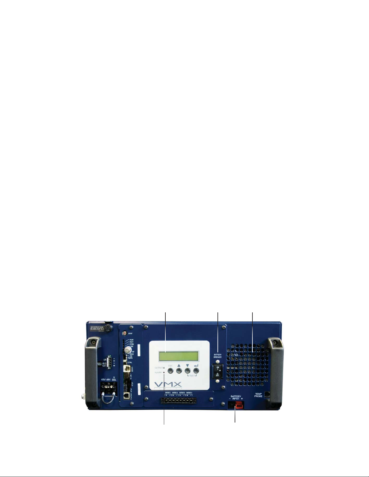
1.0 Introduction to the VMX Power Supply, continued
1.2 Inverter Overview
The inverter provides uninterrupted power to the ferroresonant transformer (via the batteries)
during line failures. During line operation, the inverter charges the batteries using a threestage (Bulk, Accept, and Float) charger.
Components:
• Smart Display: All operational functions, system testing, setup items, and alarms are
available via the Smart Display panel on the front of the VMX Power Supply (the Smart
Display is covered in detail in Section 5.2). Display functions are accessible by pressing
any of the four keys: ESCAPE, UP, DOWN, and ENTER. Backlighting is activated when
any of the four keys are pressed, and stays illuminated for one hour. There are four levels
of menu items: Operation Normal, Additional Information, Setup, and Alarms. Press
ENTER to display one level lower. Press ESCAPE to display one level higher. Press
ESCAPE to toggle between the main menu and alarm menu when alarms are present.
• Battery Breaker: The battery breaker disconnects the batteries from the inverter's
DC circuit. With the battery breaker turned off, the VMX Power Supply will not transfer
to standby mode, the inverter is disabled, and the battery charger cannot charge the
batteries. If an overcurrent is detected in the DC circuitry the breaker will trip.
• Battery Input Connector (Red = Positive; Black = Negative): The batteries plug directly
into the inverter’s battery connector. The connector is color-coded and fi ts in one direction
only.
• Inverter Cooling Fan: The inverter is equipped with a cooling fan that operates during
standby operation, or when the inverter heatsink temperature reaches 85°C. The fan
stays on until the temperature drops below 75°C. The fan also operates any time a selftest is in progress.
• Battery Temp Probe Connector: The Remote Temperature Sensor (RTS) plugs directly
into the temperature probe (RJ-11C type) connector. The sensor end of the RTS is routed
to the battery compartment and taped directly to the side of the center battery. The RTS
provides battery temperature measurements used to adjust the battery charge voltage.
Smart Display
Battery Breaker
Inverter Cooling Fan
14
Status LEDs
Fig. 1-3, Inverter Overview
Battery Input
Battery Temperature
Probe Connector
017-940-B0-001, Rev. A
Page 15
1.0 Introduction to the VMX Power Supply, continued
1.3 Optional Status Monitoring Modules
The VMX Power Supply supports a number of Alpha Technologies communications modules.
The modules may be ordered factory-installed or as user-installed fi eld upgrades.
CAUTION!
Handle these modules with extreme care. Circuit boards and logic upgrades are static-sensitive and
susceptible to damage.
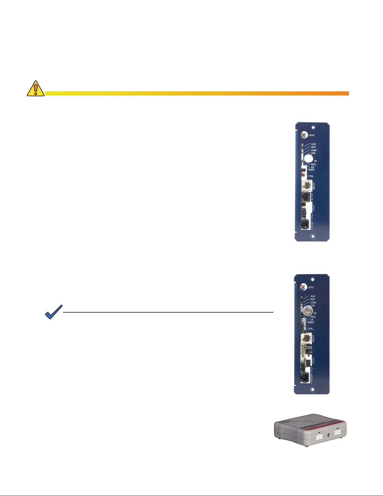
AlphaNet™ Ethernet Status Monitor (ESM)
The AlphaNet ESM (Alpha P/N 745-814-40) allows monitoring
of your VMX Power Supply via a network connection. Advanced
features and networking services provide for quick reporting and
access to critical powering information, keeping your broadband
network running reliably.
The AlphaNet ESM supports the standard networking protocols
required for effective power network management. The ESM
provides effi cient network status monitoring and diagnostics using
Simple Network Management Protocol (SNMP) and standard
MIBs. A Web interface enables authorized personnel direct
access to powerful, advanced diagnostics using a common Web
browser. No custom software is required. Refer to the AlphaNet
ESM Technical Manual, Alpha P/N 704-782-B0, for more
information.
AlphaNet™ DOCSIS Status Monitor (DSM) and Euro DSM
The AlphaNet DSM (Alpha P/N 745-825-30) and EuroDSM (745814-43) provide the same funtionality as the AlphaNet ESM, but
feature an environmentally hardened embedded DOCSIS® cable
modem for convenience and reliability. Refer to the AlphaNet
XP-DSM Technical Manual, Alpha P/N 745-814-B0, for more
information.
NOTE:
A hardware kit (Alpha P/N 745-818-22) is available for the ESM, DSM,
or EuroDSM, communications modules. This kit contains sheetmetal and
interconnect cabling, and should be ordered along with the modules.
AlphaGuard™ Battery Charge Management System
The AlphaGuard Battery Charge Management System
extends battery life by providing the precise voltage required
for each battery. You can replace single batteries as they
fail, not the entire string. It spreads charge voltage equally
across batteries, and batteries no longer need to be matched.
It adjusts for battery changes as they age. The optional
communications module monitors individual battery voltage
during inverter operation, protecting against damage from over
discharge. The AG-CMT-3 model supports 36V battery strings.
The AG-CMT-4 supports 48V battery strings. Refer to the
AlphaGuard Installation Instructions, Alpha P/N 012-306-C0,
for detailed information.
AlphaNet ESM
AlphaNet EuroDSM
AlphaGuard CMT
017-940-B0-001, Rev. A
15
Page 16

1.0 Introduction to the VMX Power Supply, continued
1.4 Optional Features
The following options can be factory installed, or upgraded in the fi eld by the user:
Local and Remote Indicator (LRI)
The LRI (red) lamp is located on the outside of pole-mount enclosures. During normal AC
line operation, the LRI remains off. The LRI comes on only when the power supply is running
in Standby Mode. Whenever a fault is detected during self-test, the LRI fl ashes to indicate
that service is required. The LRI is a simple form of status monitoring that allows operators to
check the operational status of the power supply without having to climb the pole and open
the enclosure (Alpha P/N: 740-139-20).
AC Indicator (ACI)
The AC Indicator (green lamp) is located next to the LRI on the outside of pole-mount
enclosures. As long as there is voltage present at the output, the ACI remains on. As with the
LRI, it acts as a simple form of status monitoring that allows cable technicians to check the
output status of the power supply without having to climb the pole and open the enclosure.
Alpha recommends using the ACI-LL (long life LED) because it provides much longer life
than the original light bulb design. Models for 60V and 90V are available. ACIs are not
recommended for ground mount enclosures (Alpha P/N: 740-167-21).
LA-P+ 240V (Lightning Arrestor)
The LA-P+ plugs directly into the enclosure’s convenience outlet, to provide additional
protection from voltage spikes caused by lightning and other power disturbances. It
eliminates the need for hard-wired MOVs. No additional wiring is necessary (Alpha P/N: LAP+240)
ATTENTION:
Utility safety ground must meet all local and national standards and regulations.
16
017-940-B0-001, Rev. A
Page 17

2.0 Theory of Operation
2.1 AC (Line) Operation
During AC line operation, utility power is routed into the primary winding of the ferroresonant
transformer through the contacts of the transfer isolation relay. At the same time, power is
directed to the rectifi er circuitry in the inverter which provides power for the control circuitry.
The bidirectional inverter also serves as a battery charger during AC line operation. The
ferroresonant transformer and an AC capacitor form the resonant tank circuit, which provides
excellent noise and spike attenuation, output short circuit current limiting, and output voltage
regulation. The ferroresonant transformer produces a quasi square wave output which
resembles a rounded square wave.
CAUTION!
To minimize the possibility of the transformer entering unstable operation, the VMX Power Supply
requires a minimum load of at least one ampere connected to the output. Unstable transformers will
self-correct as soon as a load of one ampere or greater is connected to the power supply.
2.2 Standby Operation
When incoming AC line voltage drops or rises signifi cantly, or a complete power outage
occurs, the VMX line monitor activates standby operation. During the transfer from AC line to
standby operation, the battery powered inverter comes on-line as the isolation relay opens to
prevent AC power from back-feeding to the utility. The energy contained in the ferroresonant
transformer continues to supply power to the load. The following changes also occur within
the VMX Power Supply:
• The control logic drives the inverter fi eld-effect transistors (FETs) on and off. This
switching action converts the DC battery current into AC current in the inverter winding of
the ferroresonant transformer, which provides regulated power to the load.
• The control logic, which includes a microprocessor and other circuits to protect the
inverter FETs from overcurrent damage, monitors the condition of the batteries and the
inverter during standby operation. Since a prolonged AC line outage would severely
discharge the batteries, resulting in permanent damage, the control logic disables the
inverter when the batteries drop to approximately 10.5Vdc per battery.
When acceptable AC line voltage returns, the power supply transfers back to AC line
operation within 10 to 20 seconds. This delay allows the AC line voltage and frequency to
stabilize before the control logic phase-locks the inverter’s output to the utility input. The
control logic then de-energizes the isolation relay, reconnects the AC line to the primary of
the ferroresonant transformer and disables (turns off) the inverter. This results in a smooth,
in-phase transfer back to utility power without interruption of service to the load. The battery
charging circuit then activates to recharge the batteries in preparation for the next power
outage. In the case of a prolonged AC outage where the inverter shuts off due to low battery
voltage, the output will return as soon as the AC line voltage returns.
NOTE:
The duration of battery-backed standby operation depends upon the type and number of batteries and the
load on the power supply.
017-940-B0-001, Rev. A
17
Page 18
2.0 Theory of Operation, continued
2.3 Charger Operation
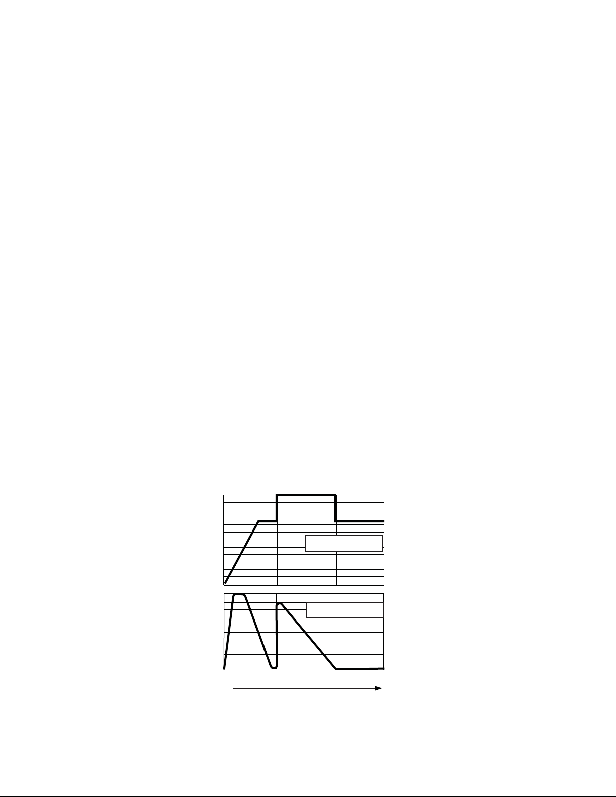
The VMX Power Supply uses a three-stage, temperature-compensated battery charger.
During AC line operation, the inverter winding on the ferroresonant transformer feeds the
charger circuit which provides BULK, ACCEPT, and FLOAT charge voltages to the batteries.
Charger Modes:
TEST: When the power supply fi rst starts, transfers back to line, or when batteries are fi rst
connected, the power supply will indicate the charger mode is TEST for a period of up to
10 minutes. The charger will operate the same as BULK mode, but with a slightly different
battery detection method. The charger mode will also indicate TEST during self-test.
BULK charge is a “Constant Current” charge. The maximum charger current is 10 Amps.
As the charge is returned to the batteries, their voltage increases to a specifi c threshold
(2.27Vdc per cell). This cycle ends when the charging current into the batteries becomes less
than 0.5A.The charger then switches to ACCEPT mode. The BULK charger mode generally
returns the battery charge state to 80 percent of rated battery capacity.
ACCEPT charge is a “Constant Voltage” charge. This voltage, 2.40Vdc (adjustable) per
cell, is temperature-compensated to ensure longer battery life and proper completion of the
charge cycle. This cycle is complete when the charging current into the batteries becomes
less than 0.5A, or approximately six hours from the time ACCEPT mode was entered. When
the batteries are fully recharged the charger switches to the FLOAT mode of operation.
FLOAT charge is a temperature-compensated “pulsed voltage” charge, averaging about
2.27Vdc (adjustable) per cell. During FLOAT mode, the batteries are fully charged and ready
to provide backup power. The charger provides a small maintenance charge to overcome the
batteries self-discharge characteristics and other minor DC loads within the power supply. As
the battery voltage reaches the “full charge” level the time delay between pulses increases.
The cell voltage is temperature-compensated at -0.005Vdc per cell per degree Celsius
(adjustable) to ensure a safe battery cell voltage and maximize battery life. The temperature
compensation is limited to an absolute battery voltage minimum of 2.20V per cell and a
maximum of 2.50V per cell regardless of the temperature compensation settings.
18
2.40
2.25
2.15
2.05
10
9
8
7
6
5
4
3
2
1
0
Charger Current
Bulk Accept Float
Fig. 2-1, Charger Modes
Volts Per Cell
017-940-B0-001, Rev. A
Page 19
%DWWHU\&RQQHFWRU
&,5&8,7%5($.(5
)DQ
&KDVVLV*URXQG6WXG
%ODFN
5HG
5HG
^%DWWHU\7HPSHUDWXUH3UREH`
-
+63+6
+6
,QYHUWHU3&%$
+6
>+6@
>+6@
5HVRQDQW&DSDFLWRU
>2LO&DS@
,QYHUWHU:LQGLQJ
3RZHU7UDQVIRUPHU
>2LO&DS@
2XWSXW:LQGLQJ
,QSXWZLQGLQJ
$X[/5,2XWSXW7HUPLQDO%ORFN
-
-
^SLQ5LEERQ&DEOH$VV\`
^6WDWXV0RQLWRULQJ(60`
^6WDWXV0RQLWRULQJ(60`
---
-
3
0LFUR%RDUG
^SLQ5LEERQ&DEOH$VV\`
>3@
3
3
3
3
-
.7DS6ZLWFKLQJ5HOD\
3
3
3
>9@RU>9@
>9@RU>9@
%URZQ
%OXH
5HG
%ODFN
>3@
>3@
>3@
>3@
3
3
$8;
$8;
3
3
9
/5,
/5,
2XWSXW&RQILJXUDWLRQ7HUPLQDO%ORFN
&KDVVLV*URXQG6WXG
3
3
3
7$36(/
9
.7DS6ZLWFKLQJ5HOD\
3
3
3
3RZHU'LVWULEXWLRQ%RDUG
3
32XWSXW-32XWSXW
32XWSXW
2XWSXW3LP%G
^SLQ5LEERQ&DEOH$VV\`
^2XWSXW9ROWDJH3'%WR3,0`
3-3
59
.,VRODWLRQ5HOD\
3
3
59
029
3
333
3
^[2XWSXWV`
32XWSXW
333-3
3
2XWSXW&RQQHFWRU%G
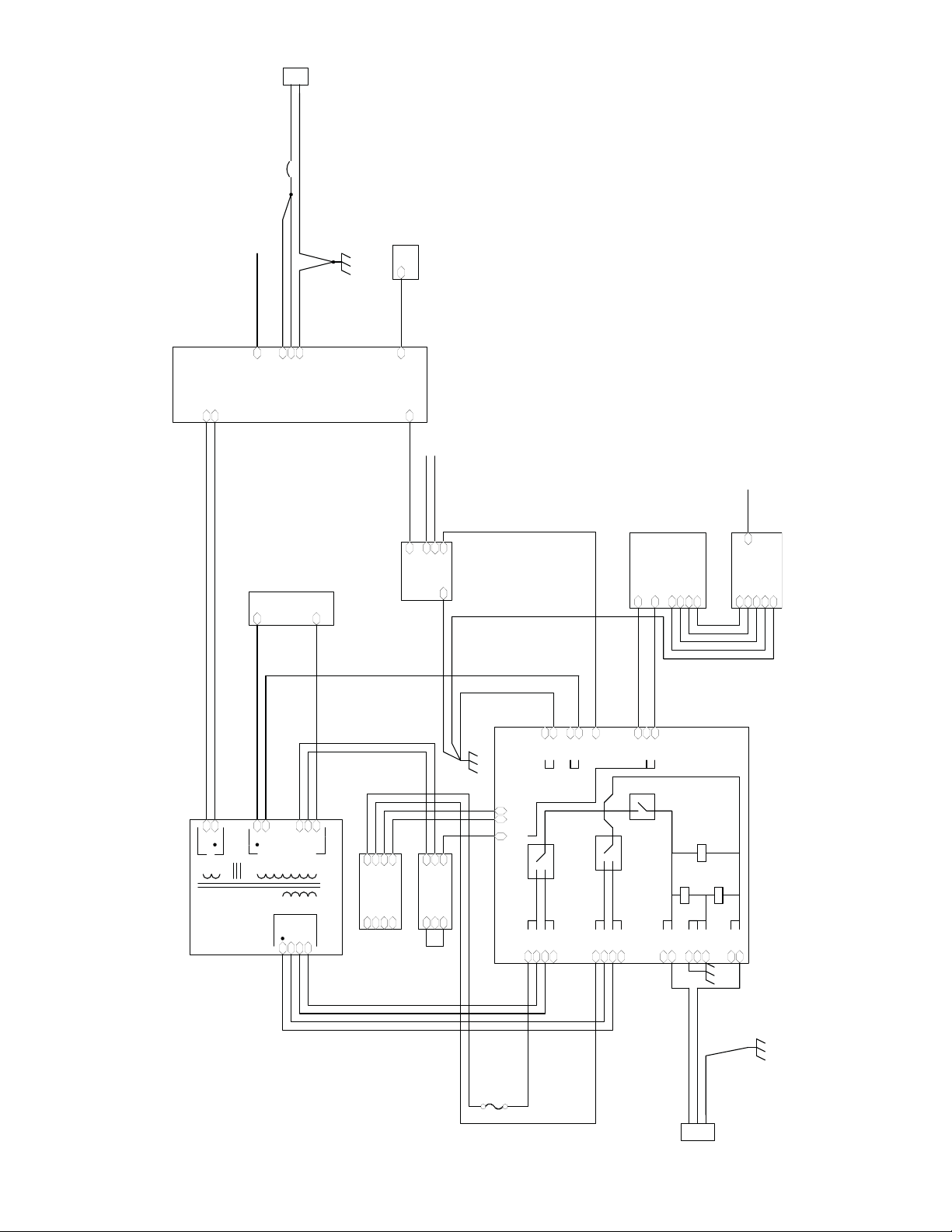
Fig. 2-2, VMX Block Diagram
029
59
029
3
3
017-940-B0-001, Rev. A
>3@
>3@
>3@
$X[2XWSXW)XVH
>)+@
>)+@
>3@
>3@
>3@
&KDVVLV*URXQG6WXG
%OXH
%URZQ
*UHHQ<HOORZ
19
,(&,QSXW&RQQHFWRU
Page 20
3.0 Installation
CAUTION!
Refer to the Safety Precautions, Utility Power Connection Notes, and Grounding Connection Notes
(pages 7-12) prior to installation.
To Ensure Operator Safety:
• Only qualifi ed personnel should install the power supply in accordance with all applicable
electrical codes.
• Use eye protection whenever working with batteries.
• Use only sealed, lead-acid type batteries with a minimum rating of 55Ah (gelled-electrolyte or
equivalent).
Unpacking and Inspection:
Remove the VMX Power Supply from the shipping container. Verify that the power supply (including
Remote Temperature Sensor) and any other ordered options have been included.
Carefully inspect the contents of the shipping container. If any items are damaged or missing, contact
Alpha Technologies or the shipping company immediately. Most shipping companies have only a
short claim period.
Preinstallation Inspection:
• During shipping, movement of components may occur. Inspect the power supply for possible
shipping-related failures, such as loosened or damaged connectors. If needed, inspect the
interior for loose or damaged connectors. Correct any discrepancies before proceeding with the
power supply installation.
• Do not attempt to install a damaged power supply without fi rst passing a complete Preinstallation
Inspection and Start-up Test.
NOTE:
Please refer to the “VMX Standby Power Supply — Quick Start Guide” (Alpha P/N 017-940-B1) that
accompanies each power supply. SAVE THE ORIGINAL SHIPPING CONTAINER.
CAUTION!
Use the original shipping container if the VMX Power Supply needs to be returned for service. If
the original container is not available, make sure the unit is packed with at least three inches of
shock-absorbing material in all orientations to prevent shipping damage. Do not use popcorn-type
material. Alpha Technologies is not responsible for damage caused by improper packaging on
returned units.
20
017-940-B0-001, Rev. A
Page 21

3.0 Installation, continued
3.1 Installation Procedure
The VMX Power Supply has been designed for shelf mounting in the horizontal confi guration
or wall-mounting in the vertical confi guration.
1. Before installing the power supply, inspect for damage, loose connectors, or other
potential failures. Correct discrepancies before proceeding.
2. For horizontal confi gurations, place the VMX Power Supply on the appropriate enclosure
mounting shelf. The unit is placed in the lower-right compartment of PME enclosures, the
upper compartment of PWE, UPE, UPE/M Enclosures, and on the equipment trays of PN
Series enclosures.
For vertical confi gurations, mount the VMX Power Supply securely to a wall allowing for
plenty of space for connections and servicing (vertical dimensions in/mm: H 11.7/297 x W
20/508 x D 9/229).
NOTE:
Alpha enclosures are designed to properly vent the VMX Power Supply. If using a non-Alpha enclosure, it is
the customer’s responsibility to ensure the VMX Power Supply remains within its environmental specifi cations.
CAUTION!
Batteries are an important part of the VMX Power Supply. Properly install and test all batteries,
battery connections, and battery cables before connecting to the power supply.
3. Make sure the battery breaker is off. After the batteries, battery connections, and battery
cables have been tested, plug the quick connects from the battery cable into the Battery
Input connection. The connector is keyed and color-coded to fi t in only one direction.
4. Plug the Remote Temperature Sensor into the Temp Probe connection. Route the sensor
end of the cable into the battery compartment, and attach it to the side of the center
battery.
5. If the optional LRI (Local and Remote Indicator) is included, connect the LRI terminal
block connections. Make connections to the auxiliary output if applicable.
6. If ESM or DSM status monitoring is used, plug the tamper switch connector into the 2-pin
TMPR connector on the front of the ESM.
6a. Connect the auxiliary output terminal block connections, if needed.
7. If using a Service Power Inserter, procede to Section 3.2. If you are not using an SPI,
connect the load to the Output 1-4 ± terminals on the terminal block and tighten clamping
screws.
017-940-B0-001, Rev. A
21
Page 22
3.0 Installation, continued
3.2 Service Power Inserter Connections
SPI Connection Procedure:
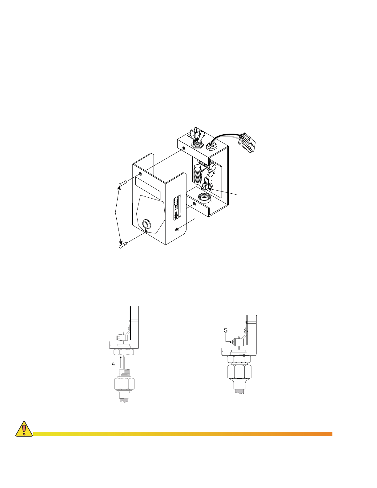
1. Ensure the SPI is unplugged from the power supply prior to removing cover.
2. Remove the two screws holding the cover to the SPI’s chassis.
3. Remove the SPI cover, exposing the circuit board and seizure screw
assembly.
2
1
Seizure Screw
Assembly
3
CAUTION!
Fig. 3-1, SPI Cover Removal
4. Insert the coaxial termination into the output port on the bottom of the SPI and tighten the
nut snug.
5. Tighten the seizure screw to 4 Nm (35 in-lbs).
Fig. 3-2, Coaxial Cable Insertion and Securing
To prevent arcing, insert the center conductor (stinger) of the coaxial termination completely inside
the seizure screw assembly (5). Tighten to 4 Nm (35 in-lbs).
22
017-940-B0-001, Rev. A
Page 23
3.0 Installation, continued
3.2 Service Power Inserter Connections, continued
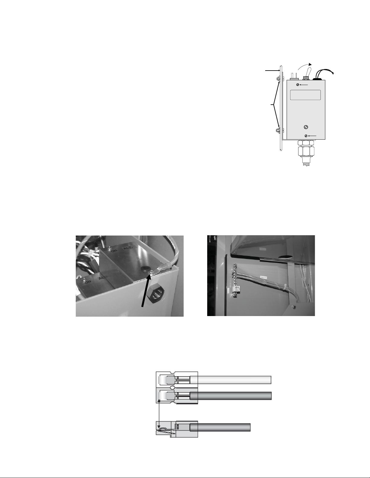
6. Replace the SPI cover and reinstall the screws.
7
Enclosure
7. Verify the switch on the top of the SPI is in the
Wall
ON position. The switch in the ON position
selects the VMX Power Supply as the power
source to the cable plant. The switch should
only be in the ALT position when a service
power supply is connected to the cable. At this
Paint-cutting
Star Washers
ALT ON
time, the standby power supply is bypassed for
service or removal
.
8. Verify the SPI is properly grounded. Typically,
grounding is accomplished by one of two
methods:
a. If the SPI has been installed with a
mounting bracket, ground connection
is made with paint-cutting star washers
Fig. 3-3, Cover Replaced,
SPI Switched On
(Fig. 3-3) used in conjunction with SPI
grounding wire.
b. If the SPI doesn’t utilize the mounting bracket, the ground connection is made via
a #8AWG wire connected to the cover of the SPI (Fig. 3-4) and terminated at the
ground bar of the cabinet (Fig. 3-5).
6
6
017-940-B0-001, Rev. A
Fig. 3-4, SPI Grounding Lug
Fig. 3-5, Enclosure Ground Bar
9. Remove the black and white wires from the Anderson connector (see Fig. 3-6) and strip
the wire ends 8mm (3/8").
Top View
White Connector
Black Connector
White Wire
Black Wire
Side View
Fig. 3-6, Wire/Connector Assembly
23
Page 24
3.0 Installation, continued
3.2 Service Power Inserter Connections, continued
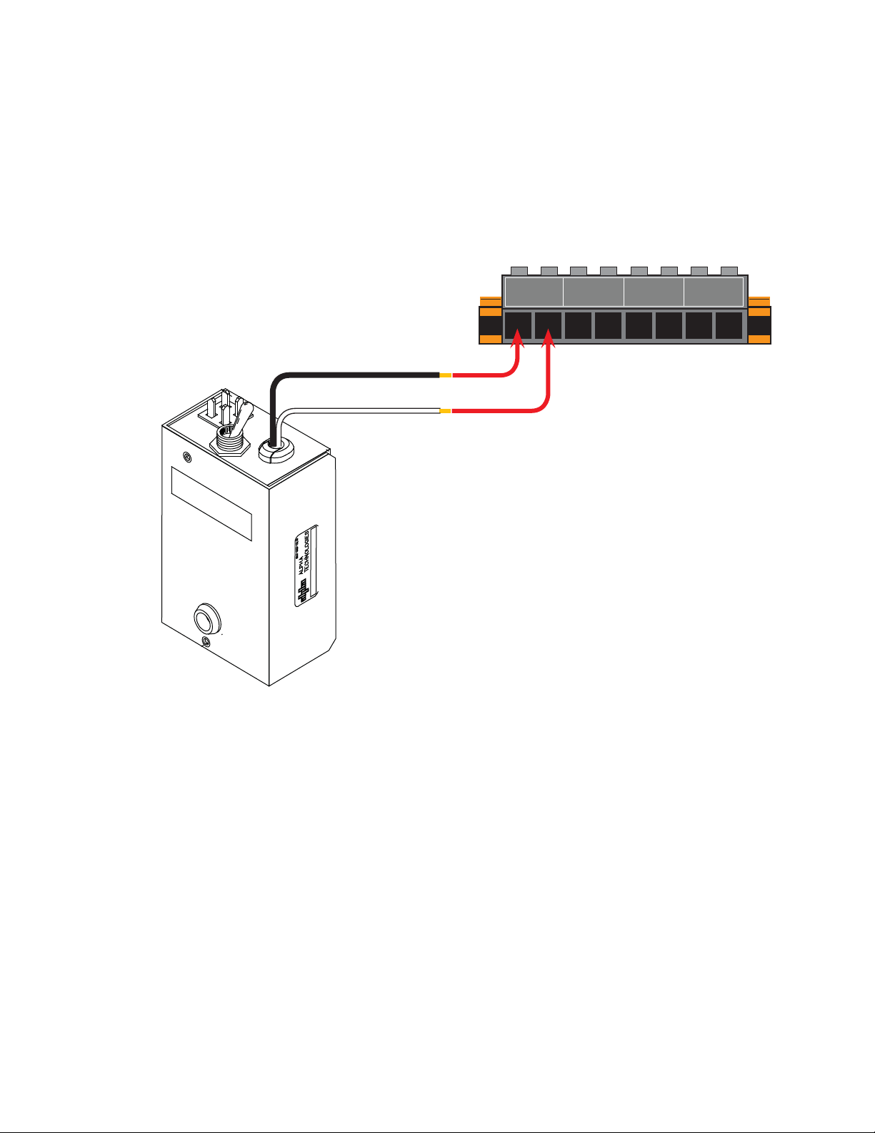
10. Insert the Black wire into the Output 1-4 + (positive) terminal and tighten the clamping
screw.
11. Insert the White wire into the Output 1-4 - terminal (negative) terminal and tighten the
clamping screw.
OUTPUT 1
+ -
OUTPUT 2
OUTPUT 3 OUTPUT 4
+ - + -
+ -
24
Fig 3-7, SPI to Output 1-4 Connection
017-940-B0-001, Rev. A
Page 25
3.0 Installation, continued
3.3 Installing the Coax Cable Connector Outputs
WARNING!
Before performing the following procedure, disconnect the power supply from line voltage
and switch the battery breaker OFF.
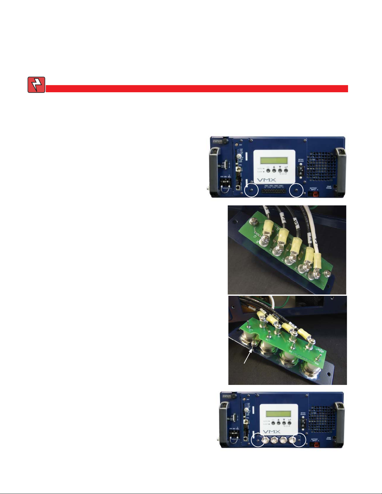
The VMX Standby Power Supply can be adapted to support four coax cable outputs.
Necessary Tools:
Philips Screwdriver
Procedure:
1. Remove the two small bolts securing
the four-output connector plate.
2. Pull the connector plate clear of the
chassis and disconnect the fi ve wires.
3. Connect the wires to their appropriate
terminals on the coax cable connector.
The neutral wire mounts below the board.
4. Secure the coax cable connector plate
to the power supply using the two small
bolts. Reconnect line power and switch
the battery breaker ON.
Neutral
017-940-B0-001, Rev. A
25
Page 26
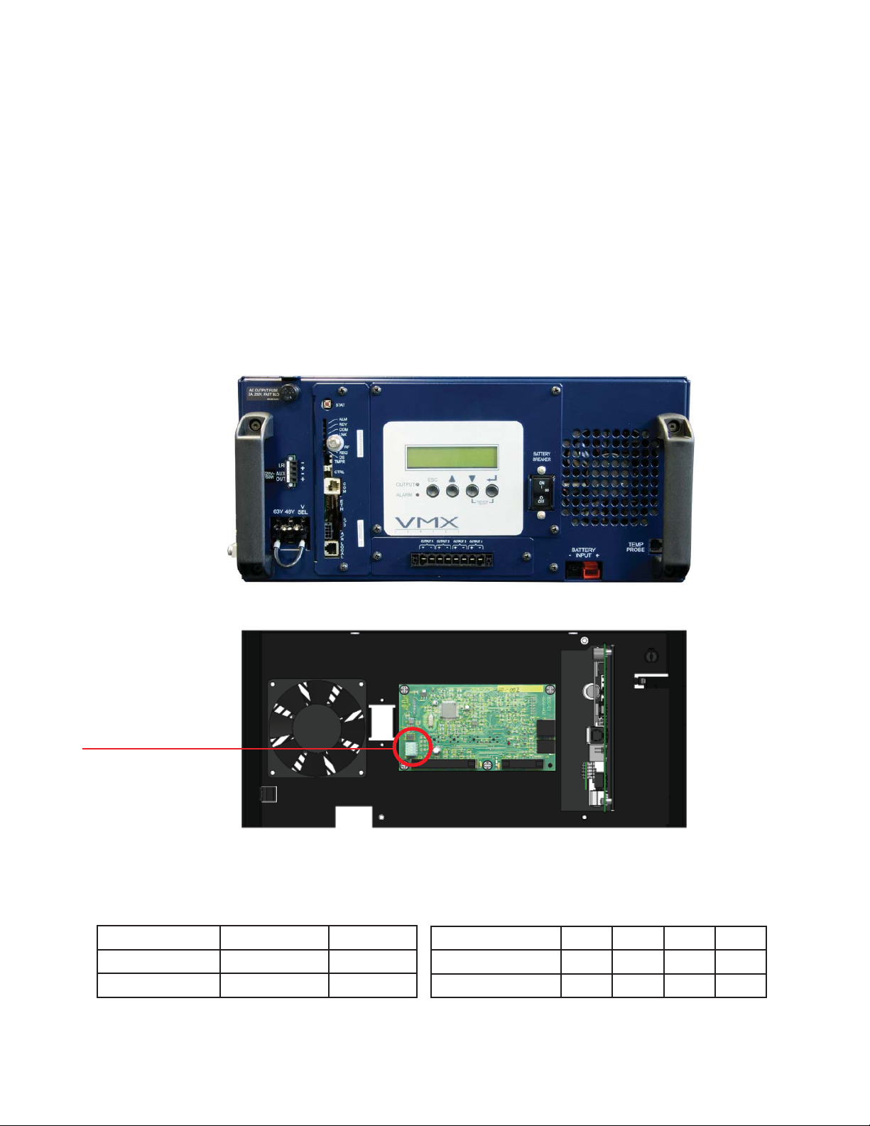
4.0 Confi guration
4.1 Micro Board Setup
The Micro Board comes factory set, but the Micro Board switches are accessible should a
confi guration change be necessary. Setup details are included in this manual as an aid to
troubleshooting, and as a reference to verify confi guration. Only qualifi ed technicians should
perform reconfi guration. To access the Micro Board, remove the eight front panel Phillips
screws indicated.
Input Voltage (SW1-1): Factory set to order. Never change this setting.
Frequency (SW1-2): Factory set to match the ferroresonant transformer operating frequency
of either 60Hz or 50Hz. This setting should never be changed.
Output Current Rating (SW1-3 and SW1-4): Factory set. Output Current Rating is set to
match the model of the power supply. Never change this setting.
Dip Switch Location
Vin, SW1-1 225V 115V
Freq, SW1-2 60Hz 50Hz
26
OFF ON
Factory set. Do not change settings.
Fig. 4-1, Micro Board DIP Switch Settings
Back of front panel
Iout 15A 22A NA NA
SW1-3 OFF ON OFF ON
SW1-4 OFF ON ON OFF
017-940-B0-001, Rev. A
Page 27
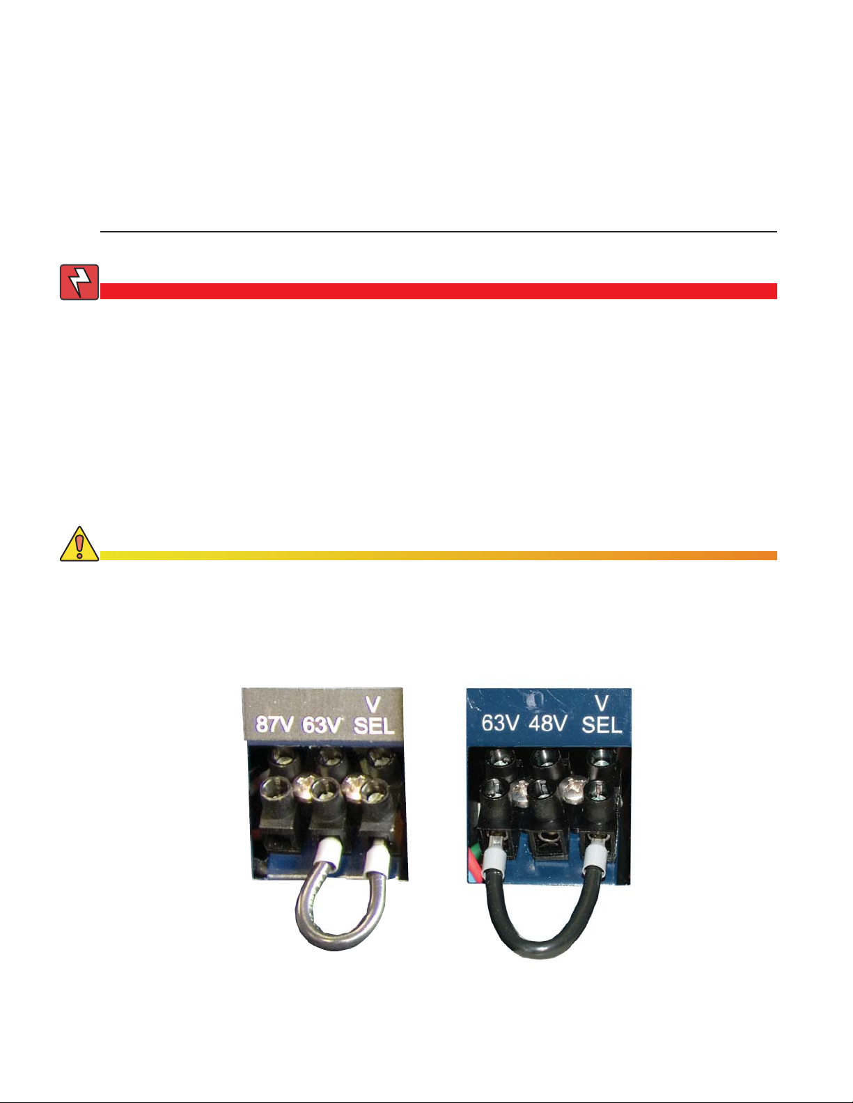
4.0 Confi guration, continued
4.2 AC Output Voltage Reconfi guration
Tools Required: Small fl at-blade torque screwdriver
The output voltage on VMX Power Supplies can be easily reconfi gured by moving the Output
Tap jumper to 63 or 48Vac, or 63 or 87Vac, depending on the VMX model.
ATTENTION:
Output voltage reconfi guration must only be performed by qualifi ed personnel.
WARNING!
Before proceeding, make certain all power has been removed from the power supply by
unplugging the power supply from the AC power source, front panel connections, and
disconnecting the battery connector. Failure to do so could expose the technician to
potentially lethal voltages.
Output Voltage Reconfi guration Procedure:
1. Unplug the Line cord. Turn off the battery breaker and unplug the battery connector on
the front of the unit.
2. Loosen the Tap Select wire screw on the terminal block. Move the Tap Select wire to the
87V, 63V, or 48V output voltage position, as desired.
CAUTION!
Do not jumper the 87V terminal, 63V terminal, or 48V terminal together.
3. Re-tighten the Tap Select wire screw and torque to 0.8 Nm (7.0 in-lbs).
4. Reconnect the front panel connections. Turn on the battery breaker, and plug in the line
cord. Verify operation of the power supply.
017-940-B0-001, Rev. A
Fig. 4-2, Transformer Output Tap Connectors
27
Page 28
5.0 Operation
5.1 Start-up and Test
AC Line Operation
1. Before making any power supply connections, verify the correct voltage, polarity, and
frequency are available from both the AC utility power source and the DC battery system.
2. Verify the AC circuit breaker (located on customer supplied service disconnect) and the
battery breaker on the VMX Power Supply are off.
3. Plug the VMX Power Supply power cord into the enclosure convenience outlet, and the
battery cable into the Battery Input connector on the front of the power supply. Plug the
RTS into the Temp Probe connection and attach it to the side of the center battery. If
applicable, connect the LRI wiring to the LRI ± terminals and the auxiliary output wires to
the AUX ± terminals on the terminal block.
4. Switch the AC (service disconnect) circuit breaker on to start initial power up. During
this stage the power supply performs a “display self-test”, and verifi es the confi guration
for the power supply. The confi guration screen looks similar to the fi gure below. After
the initial display self-test, a No Batteries alarm message appears in the Smart Display
because the battery breaker is still off. The green output LED remains off, and the red
alarm LED continues to fl ash until the battery breaker is switched ON and the power
supply qualifi es the batteries (this may take up to one minute).
OUTPUT FREQ BAT IN
90V 15A 50HZ 36V 225
Fig. 5-1, Confi guration Screen
5. Switch on the battery breaker. Within one minute the fl ashing red alarm LED turns OFF,
the green output LED turns ON, the No Battery alarm clears, and the power supply
resumes normal operation. Use the Smart Display to verify operations and Setup as
needed.
28
017-940-B0-001, Rev. A
Page 29
5.0 Operation, continued
5.1 Start-up and Test, continued
AC Line Operation, continued
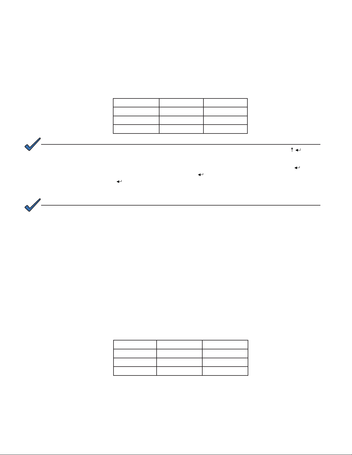
6. Use the Smart Display or a true RMS voltmeter to verify AC output (±5%) at the module’s
AC Output test point. If a non-RMS voltmeter is used, the output reading can vary by as
much as 10% due to the “quasi” square wave output of the ferroresonant transformer.
SETTING LOW (-5%) HIGH (+5%)
87Vac 82.65Vac 91.35Vac
63Vac 59.85Vac 66.15Vac
48Vac 45.60Vac 51.40Vac
NOTE:
The Confi guration Screen can be accessed any time by simultaneously pressing UP and ENTER ( ).
7. Use the Smart Display to verify VMX Power Supply operations. Press ENTER (
view Normal Information. Press ENTER ( ) again to view Additional Information. Press
ENTER ( ) a third time to view the Setup Menu. If desired, the No Battery alarm can be
disabled by changing Battery Capacity to “0”.
NOTE:
Disabling the No Battery alarm is only recommended for applications not using batteries.
Self-test Operation
1. The VMX Power Supply should be operating correctly with no alarms present. Use the
Smart Display to verify Normal and Additional Information. Verify test duration in the
Setup Menu as needed.
2. Press and hold DOWN and ENTER simultaneously to start Self-test. The test runs for a
preset time (5 to 180 minutes, set in the Setup Menu). Self-test can also be entered by
setting Self-test to ON in the Setup Menu.
3. While in Self-test mode, use the Smart Display or a true RMS voltmeter to verify output
at the terminal block OUTPUT 1-4 terminals. Output voltages should appear within ±5%
of 87Vac (for 90V units), 63Vac (for 60V units), and 48Vac (for 48V units) at nominal line
input voltage.
) to
017-940-B0-001, Rev. A
SETTING LOW (-5%) HIGH (+5%)
87Vac 82.65Vac 91.35Vac
63Vac 59.85Vac 66.15Vac
48Vac 45.60Vac 50.40Vac
4. To cancel a Self-test in progress, push and hold DOWN and ENTER a second time, or
change Self-test to OFF in the Setup Menu.
29
Page 30

5.0 Operation, continued
5.1 Start-up and Test, continued
Standby Operation
1. Perform the following procedure after successful completion of a self-test with the VMX
Power Supply operating normally in AC line mode: Momentarily fail the AC utility input
power by switching the AC circuit breaker (service disconnect) to OFF.
2. The VMX Power Supply should start operating in the inverter mode. Use the Smart
Display or a true RMS voltmeter to verify output at the OUTPUT 1-4 ± terminals. Output
voltages should appear within ±5% of 87Vac (for 90V units), 63Vac (for 60V units), or
48Vac (for 48V units) at nominal line input voltage.
3. Return the VMX Power Supply to AC Line mode by switching the AC (service disconnect)
circuit breaker to ON. The transfer back to utility power may take 10 to 20 seconds. This
delay allows the utility voltage and frequency to stabilize before the module’s phase-lock
circuitry is activated. The module then synchronizes the inverter’s waveform to the utility’s
before initiating a smooth, in-phase transfer back to utility power. Once the transfer is
complete, the smart display will report: OPER MODE = LINE.
SETTING LOW (-5%) HIGH (+5%)
87Vac 82.65Vac 91.35Vac
63Vac 59.85Vac 66.15Vac
48Vac 45.60Vac 50.40Vac
4. The VMX Power Supply is now fully operational.
30
017-940-B0-001, Rev. A
Page 31
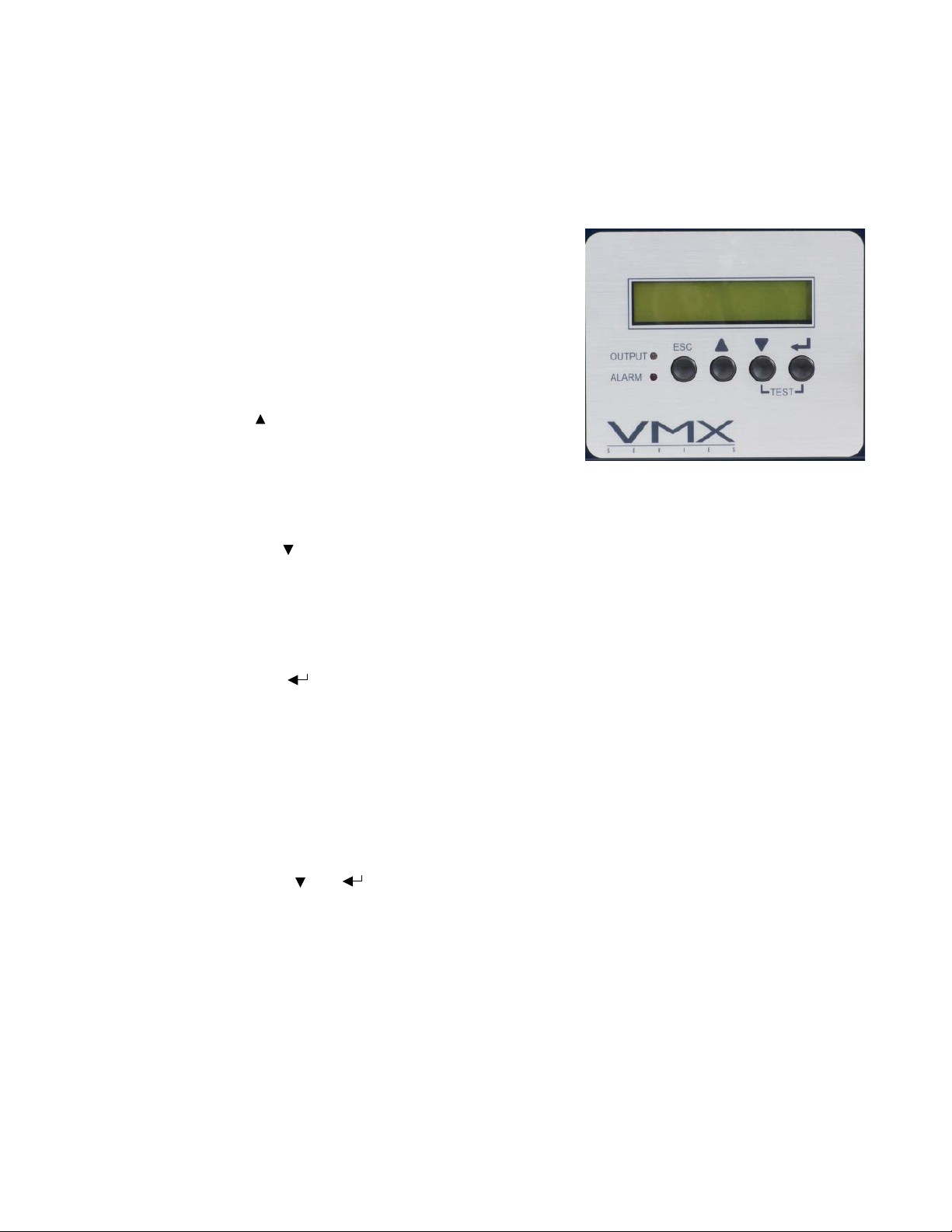
5.0 Operation, continued
5.2 Smart Display
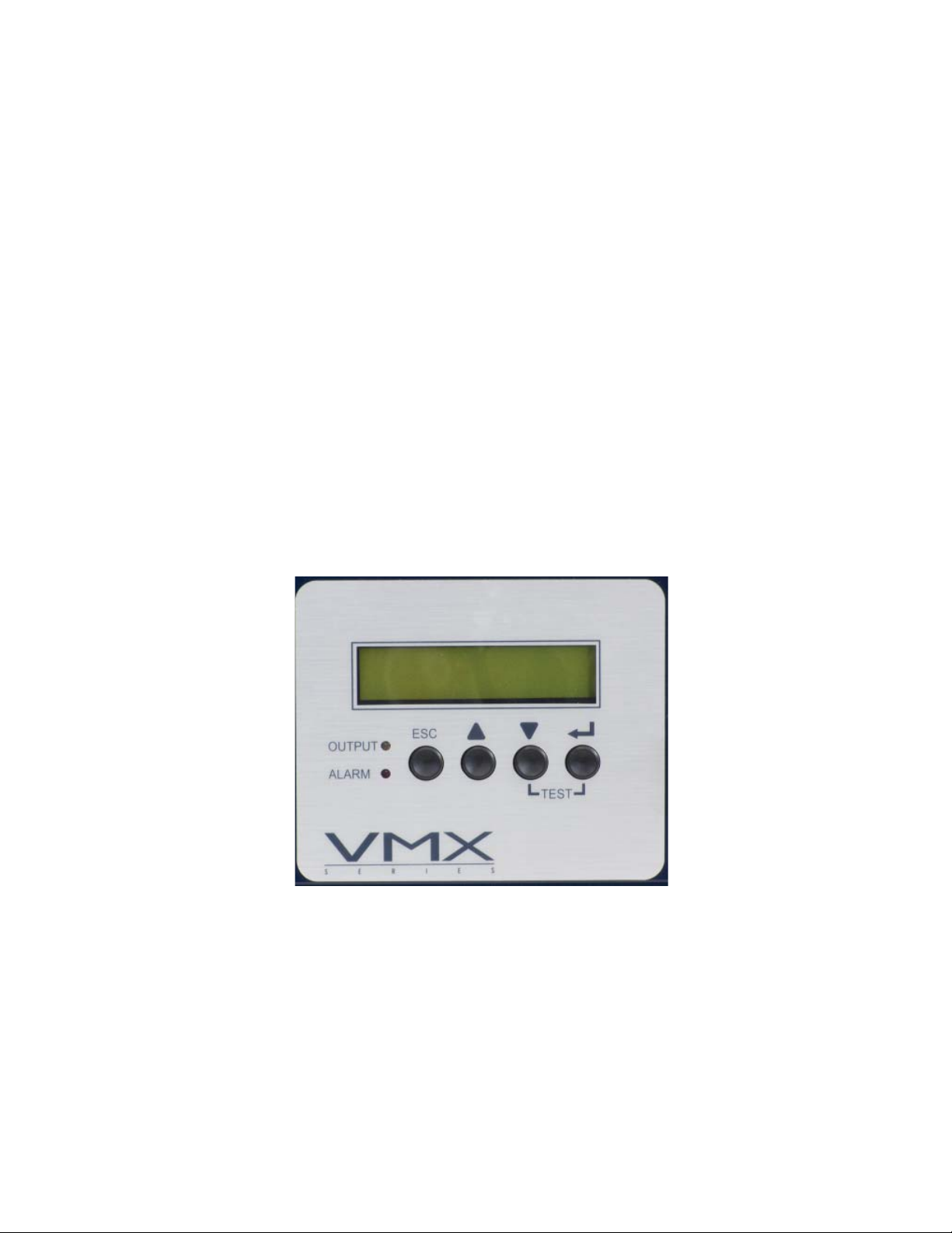
All operational functions, system testing, setup menus, and alarms are available via the
illuminated display panel on the front of the VMX Power Supply. Display functions are
accessible by pressing any of the four keys: ESCAPE, UP, DOWN, and ENTER. Descriptions
of key functions are as follows:
ESCAPE:
ESCAPE offers the following features:
Move up one level in the menu tree.
Allow the operator to leave the EDIT mode without
saving the changes made to the selected menu
item.
UP:
UP serves two primary functions:
• To scroll up in a branch of the menu tree.
• To increase a parameter (or value) while in the EDIT mode.
DOWN:
DOWN serves two primary functions:
• To scroll down in a branch of the menu tree.
• To decrease a parameter (or value) while in the EDIT mode.
ENTER:
ENTER provides the following functions:
OUTPUT FREQ BAT IN
90V 15A 50HZ 36V 225
Fig. 5-2, Smart Display
017-940-B0-001, Rev. A
• Displays the next lower level in the menu tree.
• In the EDIT mode, ENTER accepts the new value into memory.
• Depressing ENTER for two seconds or longer initiates Display Test mode. Display Test
mode switches all LED and LCD pixels (dots) on for several seconds. The display then
shows the Engineering Diagnostics screen. Press ESC to return to the Main Menu.
Self-test: and
The VMX Power Supply can manually be placed in a self-test mode by pressing DOWN and
ENTER together:
• Press and hold DOWN and ENTER simultaneously for about three seconds. A self-test
initiates and runs between 5 to 180 minutes (set in the setup menu).
• To cancel a self-test in progress, simultaneously press and hold DOWN and ENTER for
about three seconds.
31
Page 32

5.0 Operation, continued
5.2 Smart Display, continued
Display Backlighting
The display will normally be unlit. Press any key once to activate backlighting. This will
illuminate the display without deactivating Auto Scroll.
Auto Scroll
The display will normally be in the Auto Scroll mode, continually cycling through the submenu items at a two-second interval. In Auto Scroll mode the operator can quickly view menu
items without the need to press any keys.
Single Step
Pressing either arrow key will activate Single Step mode, allowing the operator to step
through the individual menu items. Each press of the arrow key will step up or down through
the sub-menu items. Press ESC to return to the Auto Scroll mode.
Direction Indicator Symbols
The rightmost character of the display (may appear on either line) indicates the proper
key function when manually scrolling. Where more than one choice is available multiple
characters will appear. The following characters or text may appear:
Access more menu items by pressing either the UP or DOWN arrow keys.
<ESC>
<ESC>
Use the ENTER key to select this function.
Use the ESCAPE key to leave the selected function without altering any values or to go back
to the previous menu in the display.
Press UP or DOWN arrows to change a display value or mode. Press ESCAPE to leave this
menu item without making any changes (and go back to the previous menu). Press ENTER
to save the change into memory. This type of multiple display choice is normally available in
the programming mode.
32
017-940-B0-001, Rev. A
Page 33

5.0 Operation, continued
5.2 Smart Display, continued
5.2.1 Operation Normal
If no alarms are present, the VMX Power Supply operates in the Operation Normal
mode. This mode allows the operator to view the primary operating parameters of the
power supply. In this mode, the display will auto scroll through the available menu
items at two-second intervals. In the Normal Operation mode, the displayed items are
all “metered” items, and are for informational purposes only (not programmable) with
respect to the operational status of the power supply.
The Normal Operation menu contains the following items:
Top Line (provides additional instructions):
• OPERATION NORMAL
•
TO MANUAL SCROLL
• FOR ADDIT’L INFO
Second Line (cycles through the following parameters):
• INPUT VOLTAGE xxxV
• BATT VOLTS xx.xV
• OUTPUT VOLTAGE xxV
• OUTPUT 1 CURRENT xx.xA
• OUTPUT 2 CURRENT xx.xA
• OUTPUT 3 CURRENT xx.xA
• OUTPUT 4 CURRENT xx.xA
• INPUT WATTS xxxxW
• xx EVENTS xxx MIN
• CHARGER MODE = fl oat
• OPER MODE = line
NOTE:
Lower case italicized items indicate variables that change according to the operating mode, setup, or
measured values. These items will appear as normal UPPER CASE text in the actual display.
017-940-B0-001, Rev. A
33
Page 34
5.0 Operation, continued
5.2 Smart Display, continued
5.2.2 Additional Information Display
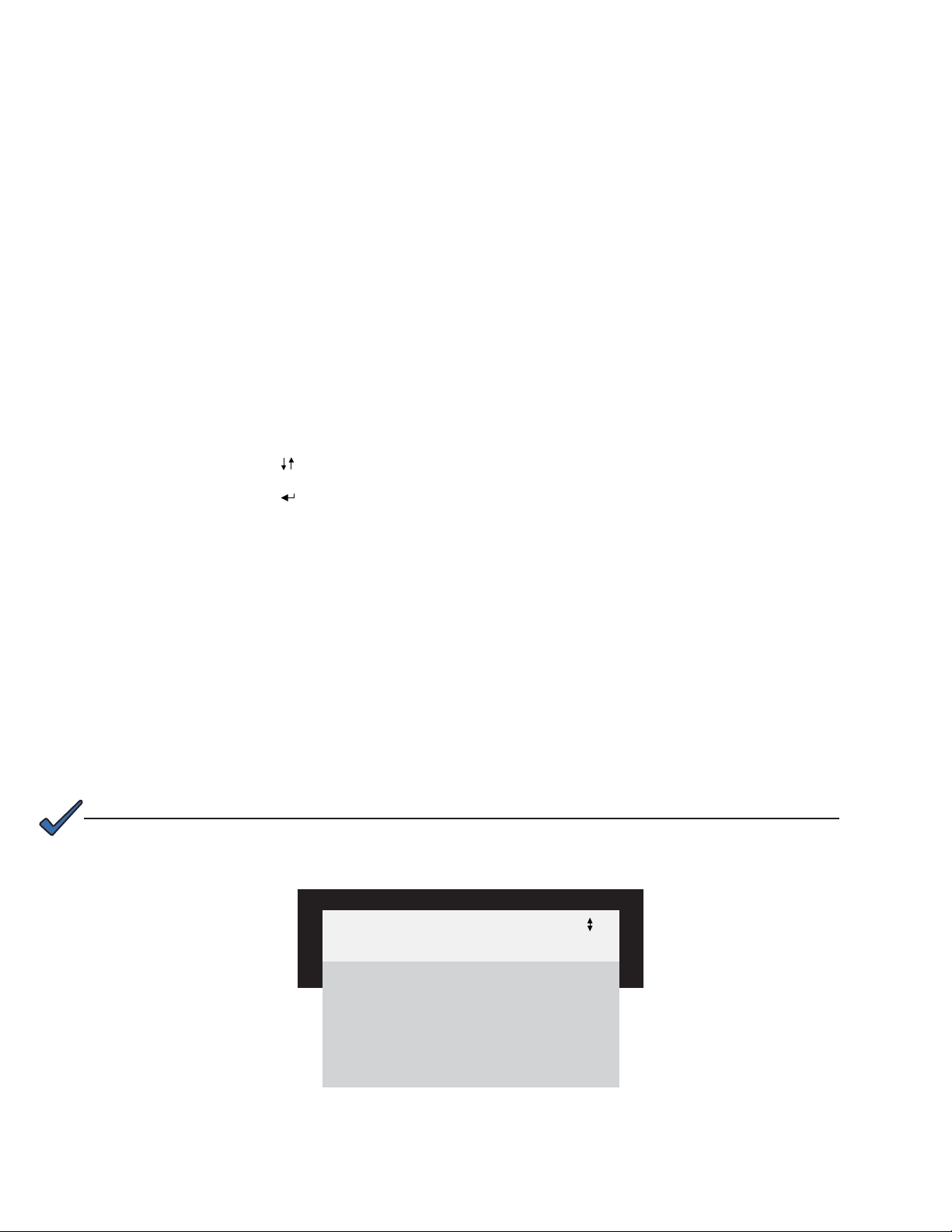
Press ENTER to activate the Additional Information display, which is an extension
of the Normal Operation mode and displays information of secondary importance to
the operator. When the Additional Information display is fi rst accessed, information
is displayed in the Auto Scroll mode. Pressing UP or DOWN allows the information
to be accessed one step at a time. Pressing ENTER will access the Setup Menu
(discussed in Section 5.2.3, Setup Menu). Pressing ESCAPE reactivates Auto Scroll
mode. Pressing ESCAPE a second time reactivates the Normal Operation display
(up one level).
The Additional Information display contains the following items:
Top Line (Provides additional instructions):
• ADDITIONAL INFO
•
TO MANUAL SCROLL
• TO SETUP MENU
• <ESC> TO SYSTEM INFO
Second Line (cycles through the following parameters):
• BATTERY TEMP xx°C
• CHARGER CURR xx.x A
• INPUT FREQ xx.x HZ
• OUTPUT WATTS xxx W
• OUTPUT VA xxx
• PERCENT LOAD xx%
NOTE:
Lower case italicized items indicate variables that change according to the operating mode, setup, or
measured values. These items appear as normal UPPER CASE text in the actual display. INPUT FREQ is not
valid during inverter operation.
• INPUT CURRENT xx.xA
ADDITIONAL INFO
BATTERY TEMP 37°C
CHARGER CURR 8.2A
INPUT FREQ 60HZ
OUTPUT WATTS 900W
OUTPUT VA 1060
PERCENT LOAD 80%
INPUT CURRENT 5.6A
34
Fig. 5-3, Additional Info Display
(Examples are given for values in the display)
017-940-B0-001, Rev. A
Page 35

5.0 Operation, continued
5.2 Smart Display, continued
5.2.3 Setup Menu
The Setup Menu is one level below the Additional Information display and is reached
by pressing ENTER. Use this menu to view and change the programmable operating
parameters of the power supply. Navigation is similar to the Normal Operation menu.
Pressing UP or DOWN accesses the Single Step mode, where sub-menu items can
be individually selected.
To select and change a value in the Setup Menu:
1. Press either UP or DOWN to put the display in the Manual Scroll mode.
2. Continue pressing UP or DOWN until the desired item displays.
3. Press ENTER to select the item for editing.
4. Use UP to increase the displayed value, or DOWN to decrease the value.
Pressing and holding either UP or DOWN for more than two seconds while in edit
mode causes the displayed value to change more rapidly.
NOTE:
The actual parameter being modifi ed in EDIT mode doesn’t change until the new data is saved by pressing
the ENTER key twice.
5. Press ENTER when the desired value displays. This accesses an additional
display, giving the operator a chance to back out of the programming mode
(ESCAPE) and not save the new value. To accept and save the new value to
memory, press ENTER.
6. Once the value is entered into memory, the display returns to the Setup Menu.
You may now check and view the new value or select additional parameters to
modify.
If an incorrect value is accidently entered, repeat the above process and enter the
proper value; or select the Set Defaults menu selection on the Setup Menu and press
ENTER twice to reset all parameters to their factory default values.
NOTE:
The Set Defaults menu selection will not reset Standby Time, Standby Events, Device Address, or Total
Runtime; the operator must manually reset these settings.
In addition to increasing or decreasing numerical values with UP and DOWN, the
operator can select ON or OFF and YES or NO. These are selected and entered as
described above. The PIM Option, CODE VER, VMX_CLASS VER, and Total Run
Time selections are informational display only items and cannot be edited. To return
to the “Operation Normal” menu from the Setup Menu, press ESCAPE three times.
017-940-B0-001, Rev. A
35
Page 36

5.0 Operation, continued
5.2 Smart Display, continued
5.2.3 Setup Menu, continued
The Setup Menu contains the following items:
Top Line (provides additional information)
• SET UP MENU
• TO MANUAL SCROLL
• <ESC> TO ADD’L INFO
Second Line (cycles through the following parameters):
Float V/C 2.27 2.1V/Cell 2.35V/Cell
Accept V/C 2.40 2.2V/Cell 2.45V/Cell
Temp Comp 5mV/Cell/ºC 0mV/Cell/ºC 5mV/Cell/ºC
Battery Capacity* 100Ah 0Ah 1000Ah
Self-test Off On Off
Test Inhibit N/A 7 days 7days
Test Interval 30 days 0 days 360 days
Test Countdown 0 days 0 days 360 days
Test Duration 10 minutes 5 minutes 180 minutes
Frequency Range 3Hz 1Hz 6Hz
Reset Out 1 No Yes
Reset Out 2 No Yes
Reset Out 3 No Yes
Reset Out 4 No Yes
Peak Current 1 Rating of the unit (15A or 22A) 3A 25A
Peak Current 2 Rating of the unit (15A or 22A) 3A 25A
Peak Current 3 Rating of the unit (15A or 22A) 3A 25A
Peak Current 4 Rating of the unit (15A or 22A) 3A 25A
RMS Current 1 Rating of the unit (15A or 22A) 3A 25A
RMS Current 2 Rating of the unit (15A or 22A) 3A 25A
RMS Current 3 Rating of the unit (15A or 22A) 3A 25A
RMS Current 4 Rating of the unit (15A or 22A) 3A 25A
Peak Retry Delay 60s 5s 301s
Peak Retry Limit 10 0 (retry disabled) 40
Peak Current Tolerance 40ms 20ms 9900ms
RMS Retry Delay 300s 60s 600s
RMS Retry Limit 10 0 10
RMS Current Tolerance 60s Read Only Read Only
Standby Time 0 minutes 0 minutes 65,535 minutes
Standby Events 0 events 0 events 65,535 events
Set Defaults No No Yes
Code Version 2.00.0
VMX_Class Version 6
Device Address 1 0 7
Total Runtime 0 days 0 days 65,535 days
Language English Spanish, French, German, Portuguese
* 100Ah = 1 battery string, 200Ah = 2 battery strings, 300Ah = 3 battery strings
Default Minimum Maximum
Table 5-1, Setup Menu Parameters
NOTE:
Refer to Section 5.3, Smart Display Glossary, for descriptions of the setup menu parameters.
36
017-940-B0-001, Rev. A
Page 37

5.0 Operation, continued
5.2 Smart Display, continued
5.2.3 Setup Menu, continued
SETUP MENU
FLOAT V/C 2.27
ACCEPT V/C 2.40
TEMP COMP 5mV
BATT CAPACITY 100Ah
SELF-TEST OFF
TEST INHIBIT —
TEST INTERVAL 30 D
TEST COUNTDOWN 3 D
TEST DURATION 10 M
FREQ RANGE 3.0HZ
RESET OUT 1 NO
RESET OUT 2 NO
RESET OUT 3 NO
RESET OUT 4 NO
PEAK CURRENT 1 15A
PEAK CURRENT 2 15A
PEAK CURRENT 3 15A
PEAK CURRENT 4 15A
RMS CURRENT 1 15A
RMS CURRENT 2 15A
RMS CURRENT 3 15A
RMS CURRENT 4 15A
PEAK RETRY DELAY 60S
PEAK RETRY LIMIT 10
PEAK CURRENT TOLERANCE 40MS
RMS RETRY DELAY 300S
RMS RETRY LIMIT 10
RMS
CURRENT TOLERANCE
60S
STANDBY TIME 65 M
STANDBY EVENTS 12
SET DEFAULTS NO
CODE VER 2.00.0
VMX_CLASS VER 6
DEVICE ADDRESS 1
TOTAL RUN TIME 365D
LANGUAGE ENGLISH
017-940-B0-001, Rev. A
Fig. 5-4, Setup Menu Display
(Examples are given for values in the display)
37
Page 38

5.0 Operation, continued
5.2 Smart Display, continued
5.2.4 Alarm Indications
In the event of a failure, the Active Alarm display indicates detected alarms and items
to check to correct the alarm condition. Major alarms also cause the red LED to fl ash.
Press either UP or DOWN to stop Auto Scroll. The arrows appearing at the right-hand
side of the display text indicate keys to press to show the next item in the menu. Use
UP or DOWN to select the alarm of interest. Press ENTER to select the alarm and
display diagnostic information. Press ESCAPE to return to the alarm list.
NOTE:
If only one alarm is active, the alarm list is bypassed and the display shows diagnostic information for the
single active alarm.
To assist the operator in troubleshooting an active alarm condition, a Help sub-menu
offers possible remedies relating to the displayed alarm. To access the Active Alarm
Help sub-menu, scroll to the alarm of interest and press ENTER. The diagnostic
information autoscrolls initially. Enter manual scroll mode by pressing either UP or
DOWN. Press DOWN to scroll through the list of remedies.
Alarms are classifi ed in two categories:
Major Alarms are indications of a serious failure within the VMX Power Supply,
such as a loss of output voltage or a failed battery charger. Any situation that causes
output failure is considered a Major Alarm. Major alarms require immediate action by
the operator to correct the failure. To correct major alarms, follow the Smart Display
on-screen instructions.
Minor Alarms indicate a less serious failure, such as defective RTS or loss of utility
power. Corrective action can be delayed for a short time. To correct, follow the Smart
Display on-screen instructions.
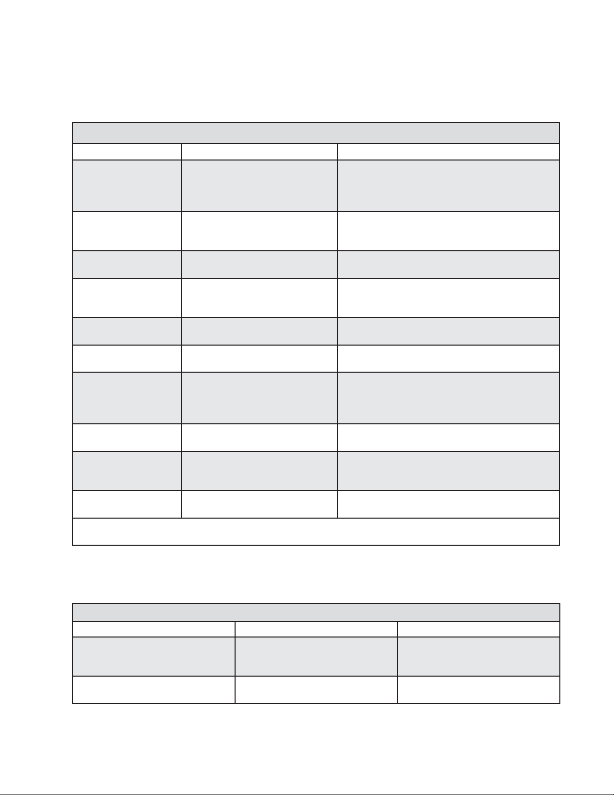
The alarm matrices on the following pages indicate the MAJOR/MINOR active
alarms, the probable cause, and troubleshooting items to check to correct the alarm
condition.
38
017-940-B0-001, Rev. A
Page 39
5.0 Operation, continued
5.2 Smart Display, continued
5.2.4 Alarm Indications, continued
Major Alarms
Active Alarm Corrective Action Probable Cause
Self-test FAIL* 1. Check batteries
2. Check inverter
LOW BATT VOLTS 1. Shutdown imminent
2. Check AC input
3. Connect generator
HIGH BATT VOLTS 1. Check charger settings 36V battery string above 45.0Vdc
NO BATTERIES 1. Check battery breaker
2. Check connections
3. Check battery fuse
LINE ISOLATION** 1. Replace power supply Line isolation has failed. All inverter operations
OUTPUT FAIL 1. Check confi guration switches
2. Output overloaded?
OUTPUT OVERLOAD 1. Check confi guration switches
2. Output short circuit?
3. Excessive load
4. Check output current
CHARGER FAILURE 1. Perform self-test Charger has failed or shutdown, possible bat-
INVERTER TEMP 1. Check fan Inverter heatsink has exceeded set temperature
CONFIG ERROR 1. Check confi guration switches
2. Check Inverter
* To clear a Latched Self-test Fail Alarm, initiate and complete a successful self-test.
** Remove and replace VMX Power Supply. Do not try to clear alarm.
• 36V battery string below 33.3Vdc
• 48V battery string below 44.3Vdc
• Inverter failure
• Batteries will not sustain load
36V battery string below 33Vdc
48V battery string below 44Vdc
48V battery string aboce 60Vdc
Absence of batteries detected
(alarm is inactive when battery capacity is set
to 0)
are suspended
The AC output has failed (check confi guration)
The VMX is overloaded
tery over-temperature
(Standby operations are suspended until
temperature drops to safe level
The VMX is improperly confi gured. Operation is
suspended until error is corrected.
Active Alarm Corrective Action Probable Cause of Alarm
BATT TEMP PROBE 1. Check connection
INPUT FAILURE 1. Utility failure
017-940-B0-001, Rev. A
Table 5-2, Major Alarms
Minor Alarms
2. Check sensor
3. Input connections
2. Circuit breaker input
Table 5-3, Minor Alarms
Remote Temp Sensor (RTS)
failed, or is not connected
Utility AC input has failed
39
Page 40
5.0 Operation, continued
5.2 Smart Display, continued
5.2.5 Control Panel LEDs
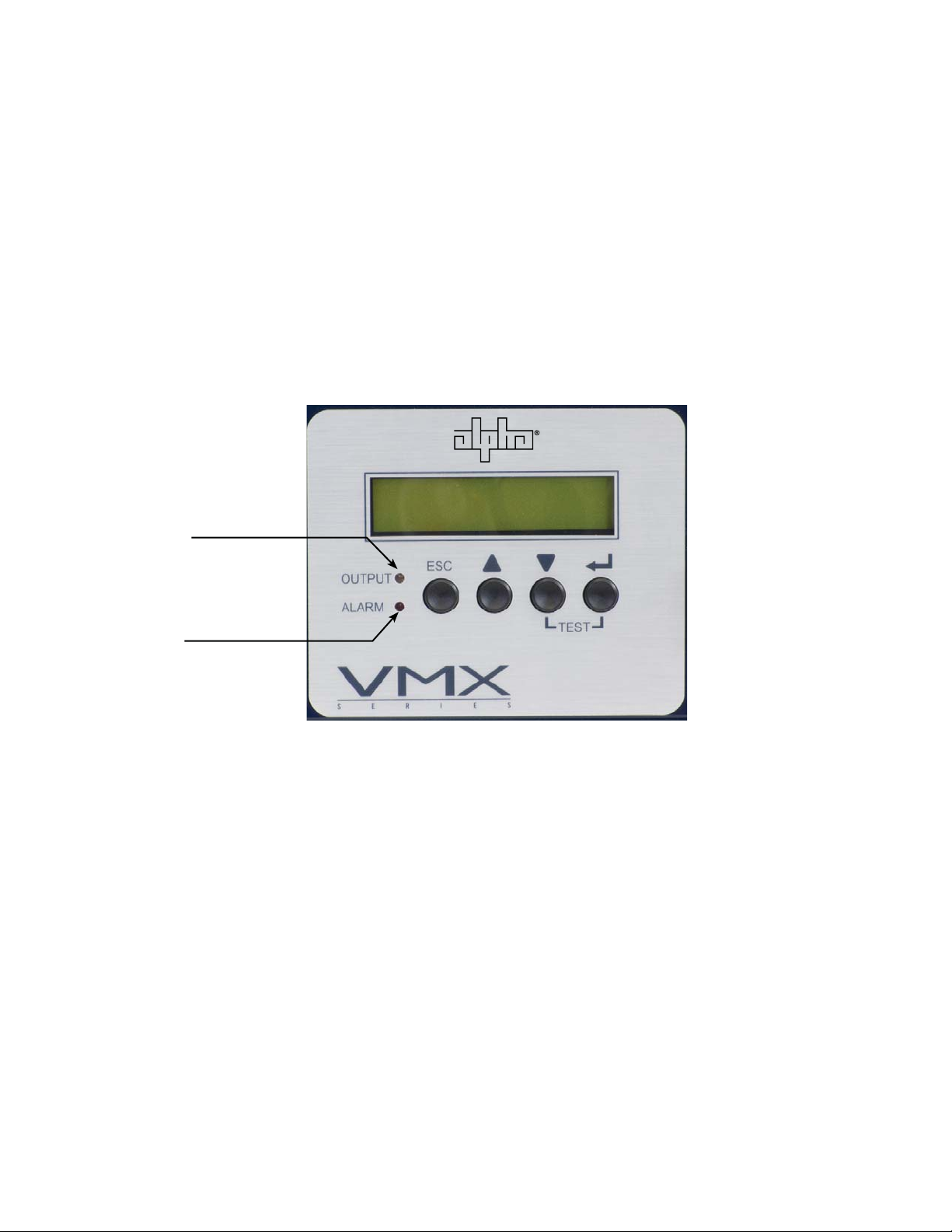
Two front panel LEDs indicate the condition and status of the VMX Power Supply.
The green Output LED, when illuminated, indicates the power supply is functioning
normally and supplying output AC to the load. A fl ashing output LED indicates that
a minor alarm has been detected. If the Output LED is off, a major alarm has been
detected.
The red Alarm LED either fl ashes or is off depending on the operating state of the
power supply. A fl ashing Alarm LED indicates that a major alarm has been detected.
This state clears when the alarm is no longer present. Normally, the red Alarm LED is
OFF indicating normal power supply operation.
Output LED
Alarm LED
Fig. 5-5, Smart Display LEDs
Major Alarms are indications of a serious failure within the VMX Power Supply,
such as a loss of output voltage or a failed battery charger. Any situation that causes
the output to be off can be considered a Major Alarm. Any Major Alarm, when
encountered, requires immediate action to be taken by the operator to correct the
failure. To correct, simply, follow the Smart Display on-screen instructions.
Minor Alarms indicate a less serious failure, such as defective RTS or loss of utility
power. Corrective action can be delayed for a short time. To correct, simply, follow the
Smart Display on-screen instructions.
40
017-940-B0-001, Rev. A
Page 41
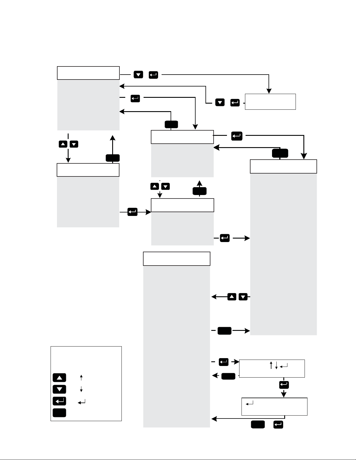
5.2 Smart Display, continued
5.2.6 Detailed Menu Structure and Navigation
OPERATION NORMAL
(Auto-scroll Information)
Input Voltage 240V
Battery Volts 40.5V
Output Voltage 90V
Output 1 Current 12.2A
Output 2 Current 12.2A
Output 3 Current 12.2A
Output 4 Current 12.2A
Input Watts xxx
12 Events 65 M
Charger Mode = Float
Oper Mode = Line
To Single
Step
OPERATION NORMAL
(Single Step Information)
Input Voltage 240V
Battery Volts 40.5V
Output Voltage 90V
Output 1 Current 12.2A
Output 2 Current 12.2A
Output 3 Current 12.2A
Output 4 Current 12.2A
Input Watts xxx
12 Events 65 M
Charger Mode = Float
Oper Mode = Line
LEGEND
Control
Panel
Key
ESC
Display
Symbol
<ESC
DOWN A
>
Description
UP Arrow
ENTER
ESCAPE
ESC
rro
w
+
Back to Operation Normal
T o Additional Information
Back to Operation Normal
(Auto-scroll Information)
Battery T emp 37ºC
Back to
Auto-scroll
T o Additional
Information
Charger Curr 8.2A
Input Freqency 60.1Hz
Output Watts 900W
Output VA 1060
Percent Load 80%
Input Current 5.6A
(Single Step Information)
Battery T emp 37ºC
Charger Curr 8.2A
Input Freqency 60.1Hz
Output Watts 900W
Output VA 1060
Percent Load 80%
Input Current 5.6A
(Single Step Information)
Float V/C = 2.27
Accept V/C = 2.40
Temp Comp = 5.0mV
Batt Capacity = 100Ah
Self-test = ON
Test Inhibit = OFF
Test Interval = 30 D
Test Countdown = 30 D
Test Duration = 10 M
Freq Range = +/- 3Hz
Reset Out 1 = No
Reset Out 2 = No
Reset Out 3 = No
Reset Out 4 = No
Peak Current 1 = 15A
Peak Current 2 = 15A
Peak Current 3 = 15A
Peak Current 4 = 15A
RMS Current 1 = 15A
RMS Current 2 = 15A
RMS Current 3 = 15A
RMS Current 4 = 15A
Peak Retry Delay = 60s
Peak Retry Limit = 10
Peak Current Tolerance = 40ms
RMS Retry Delay = 300s
RMS Retry Limit = 10
RMS Current Tolerance = 60s
Standby Time = Min
Standby Events
Set Defaults
Code Ver 2.00.0
Device Address 1
Total Runtime
Language = English
To Self-test
ESC
ADDITIONAL INFO
To Single
Step
ADDITIONAL INFO
SETUP MENU
Back to
Auto-scroll
ESC
To Setup Menu
To Single Step
Back to Auto-scroll
To Program Mode
Back to Single Step
Setup Menu
+
Testing: 10 MIN
Battery Volts 37.3V
To Setup Menu
Back to Additional Information
SETUP MENU
(Auto-scroll Information)
Float V/C = 2.27
Accept V/C = 2.40
Temp Comp = 5.0mV
Batt Capacity = 100Ah
Self-test = ON
Test Inhibit = OFF
Test Interval = 30 D
Test Countdown = 30 D
Test Duration = 10 M
Freq Range = +/- 3Hz
Reset Out 1 = No
Reset Out 2 = No
Reset Out 3 = No
Reset Out 4 = No
Peak Current 1 = 15A
Peak Current 2 = 15A
Peak Current 3 = 15A
Peak Current 4 = 15A
RMS Current 1 = 15A
RMS Current 2 = 15A
RMS Current 3 = 15A
RMS Current 4 = 15A
Peak Retry Delay = 60s
Peak Retry Limit = 10
Peak Current Tolerance = 40ms
RMS Retry Delay = 300s
RMS Retry Limit = 10
RMS Current Tolerance = 60s
Standby Time = Min
Standby Events
Set Defaults
Code Ver 2.00.0
Device Address 1
ESC
Abort
ESC
Total Runtime
Language = English
Edit Using:
Float V/C = 2.27V
To Accept New Data
<ESC> to Abort
Back to Setup
Men
ESC
u
or
ESC
<ESC>
T o Accept
New Data
Data Accepted
017-940-B0-001, Rev. A
41
Page 42
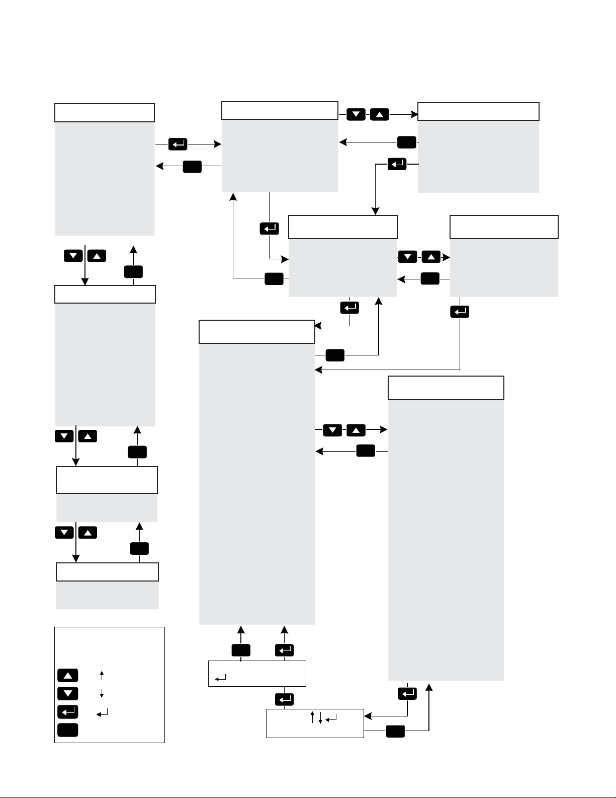
5.2 Smart Display, continued
5.2.6 Detailed Menu Structure and Navigation, continued
***ACTIVE ALARMS***
(Auto-scrolling Information)
Self-test Fail
Low Batt Volts
High Batt Volts
No Batteries
Batt T emp Probe
Line Isolation
Output Failure
Output Overload
Charger Failure
Input Failure
Inverter T emp
Confi g Error
To Single
Step
***ACTIVE ALARMS***
(Single Step Information)
Self-test Fail
Low Batt Volts
High Batt Volts
No Batteries
Batt T emp Probe
Line Isolation
Output Failure
Output Overload
Charger Failure
Input Failure
Inv Disconnected
Inverter T emp
Confi g Error
To Help
Screens for
Selected Alarm
OUTPUT OVERLOAD
(Auto-scrolling Information)
1. Output Short Ckt
2. Too Much Load
3. Chk Output Current
To Single Step
Help Screens
OUTPUT OVERLOAD
(Single Step Information)
1. Output Short Ckt
2. Too Much Load
3. Chk Output Current
ESC
ESC
ESC
LEGEND
Control
Panel
ESC
Key
Display
Symbol
<ESC>
Description
UP Arrow
DOWN A
ENTER
ESCAPE
To System Info
ESC
T o Active Alarm List
Note: Only
Detected
Alarms will
appear in this
menu
Back to
Auto-scroll
Note: Only
Detected
Alarms will
appear in
this menu
Back to
Auto-scroll
Back to
Auto-scroll
Help Screens
rro
w
ACTIVE ALARMS
(Auto-scrolling Information)
Input Voltage 240V
Battery Volts 40.5V
Output Voltage 90V
Output Current 12.2A
12 Events 65 M
Charger Mode = Float
Oper Mode = Line
T o Additional
Information
Battery T emp 37ºC
Charger Curr 8.2A
Input Freqency 60.1Hz
Output Watts 900W
Output VA 1060
ESC
To System Info
Percent Load 80%
Input Current 5.6A
To Setup Menu
SETUP MENU
(Auto-scroll Information)
Float V/C = 2.27
Accept V/C = 2.40
Temp Comp = 5.0mV
Batt Capacity = 100Ah
Self-test = ON
Test Inhibit = OFF
Test Interval = 30 D
Test Countdown = 30 D
Test Duration = 10 M
Freq Range = +/- 3Hz
Reset Out 1 = No
Reset Out 2 = No
Reset Out 3 = No
Reset Out 4 = No
Peak Current 1 = 15A
Peak Current 2 = 15A
Peak Current 3 = 15A
Peak Current 4 = 15A
RMS Current 1 = 15A
RMS Current 2 = 15A
RMS Current 3 = 15A
RMS Current 4 = 15A
Peak Retry Delay = 60s
Peak Retry Limit = 10
Peak Current Tolerance = 40ms
RMS Retry Delay = 300s
RMS Retry Limit = 10
RMS Current Tolerance = 60s
Standby Time = Min
Standby Events
Set Defaults
Code Ver 2.00.0
Device Address 1
Total Runtime
Language = English
Abort
ESC
To Accept New Data
<ESC> to Abort
T o Accept
New Data
Edit Using
Edit Using:
Float V/C = 2.27V
Back to Setup Menu
To Single Step
Back to
Auto-scroll
ADDITIONAL INFO
(Auto-scroll Information)
ESC
T o Additional Information
To Single Step
ESC
Back to Auto-scroll
Data Accepted
To Program Mode
<ESC>
ACTIVE ALARMS
(Single Step Information)
Input Voltage 240V
Battery Volts 40.5V
ESC
Output Voltage 90V
Output Current 12.2A
12 Events 65 M
T o Additional
Information
Charger Mode = Float
Oper Mode = Line
To Single Step
ESC
Back to
Auto-scroll
To Setup Menu
SETUP MENU
(Single Step Information)
Float V/C = 2.27
Accept V/C = 2.40
Temp Comp = 5.0mV
Batt Capacity = 100Ah
Self-test = ON
Test Inhibit = OFF
Test Interval = 30 D
Test Countdown = 30 D
Test Duration = 10 M
Freq Range = +/- 3Hz
Reset Out 1 = No
Reset Out 2 = No
Reset Out 3 = No
Reset Out 4 = No
Peak Current 1 = 15A
Peak Current 2 = 15A
Peak Current 3 = 15A
Peak Current 4 = 15A
RMS Current 1 = 15A
RMS Current 2 = 15A
RMS Current 3 = 15A
RMS Current 4 = 15A
Peak Retry Delay = 60s
Peak Retry Limit = 10
Peak Current Tolerance = 40ms
RMS Retry Delay = 300s
RMS Retry Limit = 10
RMS Current Tolerance = 60s
Standby Time = Min
Standby Events
Set Defaults
Code Ver 2.00.0
Device Address 1
Total Runtime
Language = English
Back to Single Step Menu
ESC
ADDITIONAL INFO
(Single Step Information)
Battery T emp 37ºC
Charger Curr 8.2A
Input Freqency 60.1Hz
Output Watts 900W
Output VA 1060
Percent Load 80%
Input Current 5.6A
42
017-940-B0-001, Rev. A
Page 43

5.0 Operation, continued
5.3 Smart Display Glossary
Battery Capacity: The capacity of the battery strings attached to this VMX Power Supply.
When batteries are not attached, the setting may be programmed to “0.” This disables
standby operations, including test mode, and disables the No Batteries Alarm. If batteries are
attached, then this setting should be programmed to the total rating of all battery strings. This
setting can be programmed to higher values to accommodate multiple battery strings (i.e., 1
battery string = 100Ah, 2 battery strings = 200Ah, 3 battery strings = 300Ah).
NOTE:
If an VMX Power Supply is used in a non-standby application, this variable must be programmed to “0” to
disable the battery maintenance cycle portion of a self-test.
BULK charge is a “Constant Current” charge. The maximum charger current is 10 Amps.
As the charge is returned to the batteries, their voltage increases to a specifi c threshold
(2.27Vdc per cell). This cycle ends when the charging current into the batteries becomes less
than 0.5A.The charger then switches to ACCEPT mode. The BULK charger mode generally
returns the battery charge state to 80 percent of rated battery capacity.
Charger Accept Voltage: Battery Accept charge voltage control in volts per cell. This
voltage, 2.40Vdc (adjustable) per cell, is temperature compensated to assure longer battery
life. It properly completes the charge cycle and is factory set for Alpha Cell batteries. If other
manufacturer’s batteries are used, consult the battery manufacturer for Accept voltage levels.
Charger Float Voltage: Battery Float charge voltage control in volts per cell. It averages
about 2.27Vdc (adjustable) per cell. It is factory set for Alpha Cell batteries. If other
manufacturer’s batteries are used, consult the battery manufacturer for Float voltage levels.
Charger Temperature Compensation: Battery charger temperature compensation control.
Programming this parameter to “0.0” will disable temperature compensation. It is factory set
for Alpha Cell batteries (5mV/cell/ºC). If other manufacturer’s batteries are used, consult the
battery manufacturer for Charger Temperature compensation ranges.
Device Address: The VMX Power Supply must have a unique address to communicate with
a system controller. The system controller uses the address as an identifi er to query the VMX
Power Supply for information. Each VMX Power Supply on the same communications bus
must be identifi ed with a value between 1 and 7.
NOTE:
The device address will not reset to 1 when factory defaults are reset.
017-940-B0-001, Rev. A
End of Battery Discharge (EOD): The point at which the batteries are fully discharged
(1.75V/C°, 18 cells for 36V inverter; 24 cells for 48V) and the power supply shuts off,
preventing permanent damage to the batteries.
Frequency Range Limit (may be used when powering with AC Generator): AC input voltage
frequency range limit. This limit establishes the acceptable input frequency range outside of
which standby operation is initiated.
Set Defaults: When programmed by the operator to YES, all the programmable data levels
(except DEVICE ADDRESS, Standby Time and Events, and Language) are reset to the
original factory settings.
Self-test: When programmed by the operator to YES, the VMX Power Supply will test
inverter operation.
Standby Events: VMX Power Supply standby events counter. This does not include self-test
events. Use the Setup Menu to reset Standby Events to zero.
43
Page 44

5. 0 Operation, continued
5.3 Smart Display Glossary, continued
NOTE:
Resetting factory defaults does not clear Standby Events or Standby Time.
Standby Time: The total amount of time the VMX Power Supply has operated in standby
mode. This does not include self-test time and thus represents the sum total number of
minutes of AC line failure since the last time this counter was reset. Use the Setup Menu to
reset Standby Time to zero.
Test Countdown: The number of days remaining before the next scheduled automatic selftest is initiated. This variable is programmable and allows the operator to select the day that
the autotest sequence will begin. This counter has no effect if test interval is set to 0.
Test Duration: Automatic self-test duration timer. The number of minutes the VMX Power
Supply performs battery maintenance cycle test. This timer applies to initiated tests
automatically or manually.
Test Inhibit: Becomes active when programmed by the operator (or when the unit runs
in inverter mode for more than 5 minutes). The VMX Power Supply delays the start of a
scheduled self-test for seven days if the test countdown is less than seven days (See Section
5.4, Automatic Performance Test for complete details).
Test Interval: Automatic self-test control timer. The number of days between battery
maintenance cycle tests. Setting this value to zero disables automatic self-test.
Total Run Time: The amount of time (in days) the power supply has functioned in any mode
of operation. This is not a re-settable value.
44
017-940-B0-001, Rev. A
Page 45

5. 0 Operation, continued
5.4 Automatic Performance Test
Automatic Self-test: The VMX Power Supply can periodically perform an automatic self-test
to verify the state of the batteries and the inverter circuitry. The automatic test feature has
several programmable parameters that affect the frequency and duration of automatic tests.
In addition to automatic testing, you can manually put the VMX Power Supply into test mode
by pressing ENTER and DOWN simultaneously. A running test may be halted manually by
pressing ENTER and DOWN a second time.
The test sequence starts with a check to verify that batteries are attached and the battery
circuit breaker is closed. If the batteries are discharged or not connected, the VMX Power
Supply does not attempt to operate in inverter test mode, and thus not drop the load if the
inverter does not have suffi cient batteries to operate. Next, the VMX Power Supply switches
to standby mode for a pre-programmed period. Successful completion of a test sequence
means that the VMX Power Supply operated normally in standby mode, the battery voltage
didn’t drop below a preset threshold and the output was stable throughout the test. Failure of
a test is indicated by a Self-test Fail alarm, which can be cleared by subsequently running a
successful test for at least one minute.
Test Control: A manual test may be initiated (or a running test may be halted) at any time
by pressing ENTER and DOWN simultaneously or by changing the Self-test switch via the
front panel interface or status communications. A self-test may also be started via the status
monitoring card.
To prevent an automatic test that is scheduled to occur in the next week, issue a Test Inhibit
command. This command is useful if periodic maintenance is scheduled to occur on the
power supply near the time that the next automatic test is to start. This control feature may
also be used when inclement weather is expected that may cause a utility failure. The Test
Inhibit command only affects an automatic test scheduled to run in the next seven days.
Multiple issues of the Test Inhibit command will result in the deferral of the next automatic test
until at least seven days after the last request. This command has no effect if an automatic
test is not scheduled to take place in the next week. Starting a test manually overrides the
Test Inhibit command.
The automatic test feature is on by default, but may be turned off. To turn auto-test off,
change Test Interval to 0 days in the Setup Menu. Auto-test may be enabled at any time by
changing the test interval to any nonzero value. The default test interval is 30 days.
Test Countdown: Informs the operator of a pending automatic test, or allows the operator to
schedule the next automatic test.
Test Duration: Test Duration can be adjusted to meet the customer’s needs. Exercise
caution when increasing the parameter because long self-tests compromise the standby
capability during, and shortly after, the test.
Standby Time and Standby Events: Counters that are not incremented during VMX Power
Supply self-tests.
017-940-B0-001, Rev. A
45
Page 46

5.0 Operation, continued
5.5 Providing Power via External Source
In the event of an extended utility failure, an external AC or DC power source can provide
backup power to the system. The backup power source allows the power supply to continue
charging the batteries, and ensures uninterrupted service to the network. Follow the
procedures outlined in the documentation and/or connection procedures listed below.
5.5.1 DC Powering
A convenient method of providing backup DC power to the network is the AlphaGen
Portable Generator. On loss of commercial AC power, the existing battery string(s)
immediately supply voltage to the inverter. After some point of battery discharge, an
operator can deploy the portable generator to the site to supply power to the DC bus.
Refer to the AlphaGen Portable Generator Operator’s Manual, Alpha P/N 041-028B0, for complete connection and operation information.
5.5.2 AC Powering
Should it become necessary to power your network with a portable AC generator,
truck-mounted AC generator, or truck-mounted inverter, the procedures below must
be followed for the protection of service personnel and system powering equipment.
Connection Procedure:
1. Determine if there is output power to the cable system by reading the Smart
Display. If there is still power to the system then check the battery voltage on the
Smart Display. If the battery voltage is greater than 34.5Vdc (3-battery system) or
46Vdc (4 battery system) then approximately one hour remains to complete the
changeover to generator power before the cable system loses customer power.
If the battery voltage is less than the previous numbers, move rapidly as there
is not much time until system failure. Use extreme caution, there are dangerous
voltages in the system that can shock you or damage the cable amplifi ers.
2. Verify the AC Input breaker from the utility powering system is in the OFF
position. This ensures that if power returns suddenly, both you and the system
will not experience a surge in power, and that when you connect the generator, it
does not put AC voltage back onto the power lines.
3. Properly ground the generator. This is accomplished by connecting a #6 AWG
wire from the grounding lug on the output panel of the generator to either a
driven ground rod or the strand ground on the pole to which the power supply is
mounted. If working with a ground-mounted power supply, locate the grounding
point inside the enclosure and clamp on to that point.
WARNING!
Grounding of the generator is mandatory for safety and for proper operation of the power
supply.
46
4. After properly grounding the generator, unplug the power supply from the
convenience outlet inside the enclosure and plug the power supply input cable
into the generator output. An approved extension cord must be used.
017-940-B0-001, Rev. A
Page 47

5. 0 Operation, continued
5.5 Providing Power via External Source, continued
5.5.2 AC Powering, continued
5. Start and operate the generator according to the generator operation manual.
6. If the generator kilowatt rating is twice the kilowatts used by the power supply
indicated on the Smart Display, leave the battery breaker on and the generator
will charge the batteries. If the generator fails the power supply will continue
to provide battery backup. If the generator output is not approximately twice
the kilowatt rating indicated on the Smart Display, switch the battery breaker
off (this reduces the load on the generator but battery backup of the system is
unavailable).
7. In either case, after the power from the generator is applied to the power supply,
use the Smart Display to increase the Frequency Input Tolerance to ±6Hz from
the normal ±3Hz. This limits the power supply from switching to battery backup
if the generator occasionally does not operate on the proper frequency. It is not
uncommon for smaller (4 kilowatt or less) sized generators to get “off frequency”
due to the step loading of the power supply.
5.5.3 Using a Truck-mounted Inverter or Generator
WARNING!
Ground the vehicle before operating the truck inverter or truck-mounted generator. Failure
to do so will place service personnel at risk for electric shock.
To use a truck-mounted inverter or generator follow the steps listed in Section
5.5.2 with the additional step of grounding the truck. Run the ground wire from an
unpainted point on the truck chassis to either a driven ground rod or strand ground
to complete the grounding circuit. The rubber tires on the truck insulate it from being
grounded in all but the most exceptional circumstances.
017-940-B0-001, Rev. A
47
Page 48

5.0 Operation, continued
5.6 Resumption of Utility Power
WARNING!
Use caution when disconnecting a generator and reconnecting to utility power. Dangerous
voltages are present.
CAUTION!
Care must be exercised to ensure that both powering systems are not connected at the same time,
or damage to the power supply and/or the generator may result.
1. Use a voltmeter to verify the input voltage is within specifi cations before turning on the
AC voltage input breaker.
2. Once the proper voltage is present, verify the battery voltage indicated on the Smart
Display is greater than 31.5V for a 36V system, or 42V for a 48V system. Disconnect the
power supply from the generator output and plug the power supply input cord into the
convenience outlet within the enclosure. The power supply operates on battery backup
for a short period of time. Exercise caution during this changeover. The grounding circuit
to the power supply is broken while in the act of unplugging and reconnecting the power
supply.
If the batteries are at or below the low voltage cutoff, the power supply will not transfer to
battery back-up and there will be a momentary power outage to the cable system while
you make this changeover.
3. Turn on the AC input power.
4. Shut down the generator and remove the grounding system.
48
017-940-B0-001, Rev. A
Page 49
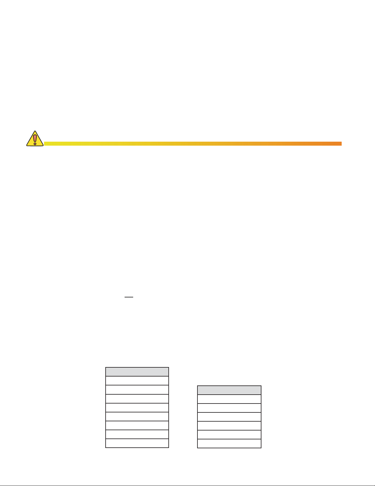
6.0 VMX Power Supply Maintenance
Maintenance must be performed every three to six months. By establishing a routine maintenance
program, and following the guidelines contained in this manual, the VMX Power Supply will provide
years of trouble-free operation.
Care of the batteries is the fi rst step in any power supply maintenance program. In addition to
voltage checks, visually inspect the batteries for signs of cracking, leaking, or swelling. To aid in
quick identifi cation and tracking of voltages in the maintenance log, number the batteries inside the
enclosure using labels or masking tape, etc. Batteries are temperature sensitive and susceptible to
overcharging and undercharging. Since batteries behave differently in the winter than in the summer,
Alpha’s battery chargers automatically compensate for changes in temperature by adjusting fl oat and
accept charge voltages.
CAUTION!
• The VMX Power Supply must be serviced by qualifi ed personnel.
• Alpha Technologies is not responsible for battery damage due to improper charger voltage settings.
Consult the battery manufacturer for correct charger voltage requirements.
• When removing batteries, ALWAYS switch the battery breaker off before unplugging the battery connector.
• Always wear safety glasses when working with batteries.
6.1 Check Battery Open Circuit Voltage
Prior to testing, record the battery manufacturer, date code, lot number, and power supply’s
model number and serial Number.
Inspect all battery posts, verify that all connections are clean and tight. Reapply corrosion
inhibitor.
Disconnect the AlphaGuard CMT (if used) and switch the front panel battery breaker of the
VMX Power Supply Inverter to OFF. Disconnect the battery connector from the inverter and
measure the individual voltage across each battery. The difference between any battery in the
string should not be greater than 0.3Vdc. Defective or marginal batteries should be replaced
with an identical type of battery. Record the unloaded battery voltages in the maintenance
log.
6.2 System Information
Observe and record the following system information from the Normal Operation and
Additional Information menus in the maintenance log. See Section 6.9.
Operation Normal
Input Voltage
Output Voltage
Output Current (1-4)
Standby Events
Battery Voltage
Charger Mode
Total Standby Time
Operation Mode
Additional Information
Battery Temperature
Output Voltage
Input Frequency
Output Watts
Output VA
Percent Load
017-940-B0-001, Rev. A
49
Page 50

6.0 VMX Power Supply Maintenance, continued
6.3 Check Battery Voltage Under Load
In order to completely verify a battery’s ability to supply load, the battery must be tested while
under a load. This is the most accurate method to determine the condition of the batteries.
If available, use a battery load tester and follow the manufacturer’s instructions to test the
individual batteries. If a battery load tester is not available, use the following procedure.
WARNING!
Weak or severely discharged batteries can explode when put under load. As an added
safety precaution, place the enclosure’s door between the operator and batteries before
attempting standby operation.
NOTE:
• If installed, disconnect the AlphaGuard–Charge Management Technology Card (AG-CMT) prior to
measuring battery voltage.
• Even with an AG-CMT present, any battery which fails the 0.3V load test must be replaced with an
identical type of battery.
Test Procedure:
1. If the batteries appear functional (i.e., if they have passed “Check Battery Open Circuit
Voltage” test), reconnect the Battery Input connector to the Inverter Module, switch on the
battery breaker, and wait for the No Batteries alarm to reset.
2. Simultaneously press ENTER and DOWN on the Smart Display to manually start an
inverter self-test.
NOTE:
The VMX Power Supply will not go to self-test if the batteries are defective or disconnected. Initially, the
battery voltage will appear to drop quickly (this is “surface” charge), but the battery voltage should stabilize
quickly.
3. When the battery voltage appears to stabilize (approximately 8-10 minutes), use a
multimeter to measure individual battery voltages under load.
4. The difference between any of the batteries should not be greater than 0.3Vdc. Replace
defective or marginal batteries with an identical type of battery.
5. Record the loaded battery voltages in the maintenance log.
50
017-940-B0-001, Rev. A
Page 51

6.0 VMX Power Supply Maintenance, continued
6.4 Check Battery Charger Voltage
The advanced three-stage charging features of the VMX Power Supply are completely selfmonitoring. During normal power supply operations, the power supply continuously verifi es
the operating condition of the battery charger. If, for any reason, the battery charger fails, a
Charger Fail alarm displays on the Smart Display. No operator voltage checks are required.
6.5 Check Battery Terminals and Connecting Wires
Check each battery terminal and connection. Verify the posts are clean and the crimped
connectors are tight. Terminal connectors should be torqued in accordance with the battery
manufacturer's recommendation. If there is an in-line fuse in the battery cable, check the fuse
holder and fuse. Verify the terminals are properly protected with an approved battery terminal
corrosion inhibitor such as NCP-2. Record date of maintenance in the maintenance log.
NOTE:
Whenever the battery breaker is turned off, or the batteries are not connected, the VMX Power Supply
automatically reports a No Batteries alarm. This is normal, and is a built in safety feature. The unit does not
attempt inverter operations, either standby or test, during a No Battery alarm.
6.6 Check Output Voltage
Measure the AC output voltage at the VMX Power Supply Transformer Module’s Output test
points using a true RMS AC voltmeter. Only use a True RMS meter, as other meters may not
give a correct reading.
Output voltages should appear within ±5% of rated output at a nominal line input.
Record the voltages in the maintenance log. Output voltages can also be observed by using
the Smart Display.
Setting Low (-5%) High (+5%)
87Vac 82.65Vac 91.35Vac
63Vac 59.85Vac 66.15Vac
48Vac 45.60Vac 50.40Vac
6.7 Check Output Current
With the VMX Power Supply in normal operating mode, observe the Output current values
indicated by the Smart Display. The values of output current will be dependent on the total
amount of load connected to each output of the power supply. Record the current in the
maintenance log.
017-940-B0-001, Rev. A
51
Page 52
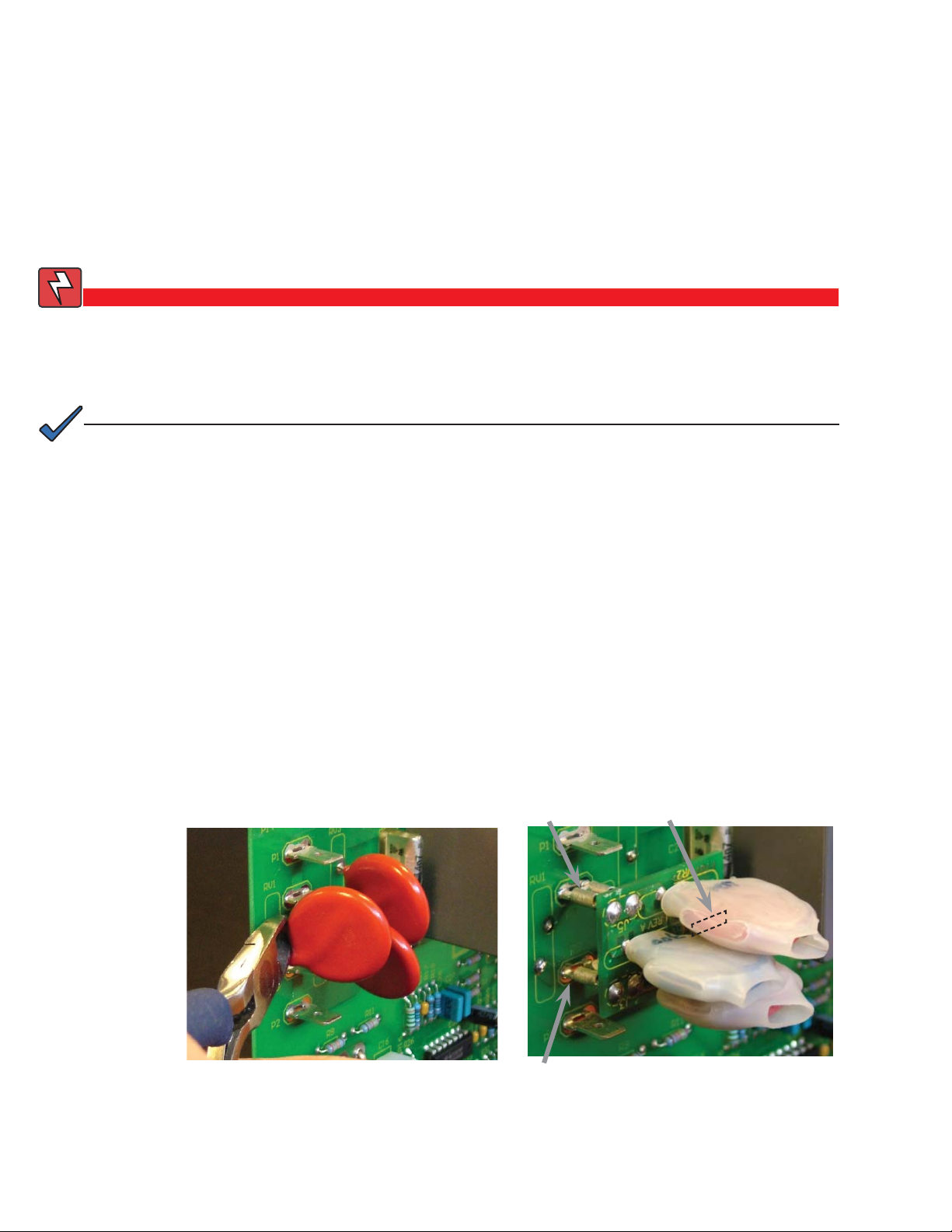
6.0 VMX Power Supply Maintenance, continued
6.8 Replacing the Metal Oxide Varistors
The Power Distribution Board (PDB) uses three Metal Oxide Varistors (MOVs) for lightning
suppresson. If the MOVs fail, Alpha offers a replacement board option to bring the unit back
into service.
Tools Required: #2 Phillips screwdriver
Wire cutters
WARNING!
Before proceeding, verify all power has been removed from the power supply by
unplugging the power supply from the AC power source and disconnecting the battery
connector. Failure to do so could expose the technician to potentially lethal voltages.
NOTE:
Use a backup power source at this time as the VMX will not provide any power during this peocedure.
Procedure:
1. Remove all power to unit. Turn off battery breaker and unplug battery connector. Unplug
line cord and remove all front panel connectors.
2. Remove the screws securing the power supply front panel. Set the screws aside in a safe
location.
3. Tip the front panel forward to gain access to the Power Distribution Board.
4. Remove the damaged MOVs using your wire cutters. See Fig. 6-1.
5. Replace with the MOV replacement card option (Alpha P/N 704-804-20). Position the
card over P3, P9, and P8 and seat fi rmly as shown in Fig. 6.2.
6. Replace the front cover.
P3
P8 (not shown)
52
Fig. 6-1, MOV Removal
P9
Fig. 6-2, MOV Replacement
017-940-B0-001, Rev. A
Page 53
6.0 VMX Power Supply Maintenance, continued
6.9 Maintenance Log
Battery Maintenance
Battery Number 1 2 3 4 5 6 7 8
Battery Manufacturer
Date Code/Lot Number
Terminal Check
Voltage (Unloaded)
Voltage (Loaded)
VMX Maintenance
Model Number
Serial Number
Normal Operation
Input Voltage
Output Voltage
Output Current (1-4)
Battery Voltage
Standby Events
Standby Time
Charger Mode
Operation Mode
Additional Information
Battery Temperature
Charger Current
Input Frequency
Output Watts
Output VA
Percent Load
Commissioning
Service Technician
Date Serviced
017-940-B0-001, Rev. A
53
Page 54

7.0 Specifi cations
Model: VMX 615CE VMX 622CE-48 VMX 915E
Electrical
Input Voltage: 230Vrms 230Vrms 230Vrms
Input Tolerance: Operating: ±158 to 292Vrms Operating: ±158 to 292Vrms Operating: ±158 to 292Vrms
Nominal Input Current1:5A 7A 7A
Input Frequency: 50Hz, ±3Hz 50Hz, ±3Hz 50Hz, ±3Hz
DC Voltage: 36VDC 48VDC 36VDC
Low DC Voltage Cutout: 1.75V/Cell 1.75V/Cell 1.75V/Cell
Output Voltage: 63V rms 48/63V rms (Field Selectable) 63/87V rms (Field Selectable)
Output Regulation, High TAP2:
Output Regulation, Low TAP2:
Rated Output Current: 15A rms 22A rms 15A rms
Output Confi guration: 4 Programmable Outputs 4 Programmable Outputs 4 Programmable Outputs
Output Frequency: 50Hz, ±1Hz (Inverter Operation) 50Hz, ±1Hz (Inverter Operation) 50Hz, ±1Hz (Inverter Operation)
Waveform: Quasi Square wave Quasi Square wave Quasi Square wave
Slew Rate: <200 V/ms, <100 V/ms typical <200V/ms, <100V/ms typical <200V/ms, <100V/ms typical
Crest Factor Ratio (Peak: RMS): 1.3:1 typical 1.3:1 typical 1.3:1 typical
Auxiliary Output 150W rated UPS: 205-260V (line), 170-265V (Inv) 205-260V (line), 170-265V (Inv) 205-260V (line), 170-265V (Inv)
Effi ciency @ Default TAP Settings
@100% Load: 91% typical at nominal input
@75% Load: 90% typical at nominal input
@50% Load: 88% typical at nominal input
@25% Load: 80% typical at nominal input
On Inverter (40 to 100% load): 80% typical
Overload Protection
Fold back (T ypical @ Nominal Input)
87V TAP: N/A N/A 24A rms
63V TAP: 33A rms 35A rms 33A rms
48V TAP: N/A 45A rms N/A
Output Current Into Short (@ Nominal Input)
87V TAP: N/A N/A <22.5A rms
63V TAP: 29A rms typical <30A rms 29A rms typical
48V TAP: N/A <33A rms N/A
Overload Current Operation
0% to 110% Load: Continuous Operation
110 to 115% Load: Continuous Operation with Alarm
115 to 125% Load: Shut Down approx. 30min
125 to 150% Load: Shut Down approx. 10min
>150% Load: Shut Down <10sec
Battery Charging
Charge Current
Temperature Compensation
3
: 10A
:
Constant Current Operation: High Rate Charge to 90% Capacity
Constant Voltage Operation: 2.40V/Cell (Programmable)
Environmental
Operating Range: –40 to 55°C at Front Air Inlet of Power Supply
Humidity: 0 to 95% non-condensing
Altitude: 0 to 10000ft (3000m) abov e sea leve l
Mechanical Vertical Mount Shelf Mount Vertical Mount Shelf Mount Vertical Mount Shelf Mount
Height (in/mm): 11.7/297 8.4/212 11.7/297 8.4/212 11.7/297 8.4/212
Width (in/mm): 20/508 16.5/420 20/508 16.5/420 20/508 16.5/420
Depth (in/mm): 9/229 12.5/317 9/229 12.5/317 9/229 12.5/317
Weight (lbs/kg): 67/30.5 67/30.5 67/30.5 67/30.5 67/30.5 67/30.5
Front Panel Display (LCD): 2 x 20 Character LCD 2 x 20 Character LCD 2 x 20 Character LCD
Front Panel Indicators (LED): Output Status & Alarm Output Status & Alarm Output Status & Alarm
Finish: Dark Blue Powder Coat Dark Blue Powder Coat Dark Blue Powder Coat
Communication
Status Monitoring
4
: Optional ESM/DSM
Agency
Safety Recognition: EN 50091-1-2, IEC 60950, CB Scheme. CE EN 50091-1-2, IEC 60950, CB Scheme.
Emissions: EN 50091-2, CE Class A
Notes:
1
Batteries fully charged
2
Output regulation at nominal input frequency. Frequency variations will proportionally affect the output voltage (i.e., a 1% reduction in frequency will result in approximately a 1% drop in output voltage)
3
Varies with input line voltage and output load. 4 Status monitoring and embedded transponders are optional.
Line Return: ±169 to 281Vrms Line Return: ±169 to 281Vrms Line Return: ±169 to 281Vrms
±
3%
±
4%
±
3%
±
4%
±
3%
±
4%
-5mV/Cell/°C (Programmable)
54
017-940-B0-001, Rev. A
Page 55
7.0 Specifi cations, continued
7.1 Safety and EMC Compliance
European Union Product Compliance:
Safety (CE):
Low Voltage Directive: 72/23/EEC, 93/68/EEC
Technical Standards: EN 50091-1:1993, EN 60950:1992
Electromagnetic Compatibility (EMC):
EMC Directive: 89/336/EEC, 92/31/EEC, 93/68/EEC
Technical Standards: EN 50091-2:1996
017-940-B0-001, Rev. A
55
Page 56

8.0 Troubleshooting
The Smart Display troubleshooting guide is designed to display typical symptoms, causes and
solutions, starting with the most obvious and working systematically through the VMX Power Supply.
Alpha Technologies recommends that the power supply’s maintenance log accompany units brought
in for bench service to aid the operator in troubleshooting the problem.
8.1 Return/Repair Information
In the event the Power Supply must be returned to Alpha Technologies for service, a Return
Material Authorization (RMA) form must accompany the unit. The form can be found at
Alpha’s Web site (www.alpha.com/support). Follow the instructions contained in the form to
obtain an RMA. Once an RMA number has been issued, pack the unit per instructions and
return to the service center assigned by Alpha Technologies. Or, if preferred, contact Alpha
Technologies at (800) 322 5742 for assistance.
NOTE:
Any information pertaining to the nature of the power supply failure or problem, along with a copy of the power
supply’s maintenance log, should be included with the returned VMX Power Supply.
8.2 Parts Ordering Instructions
When ordering parts from Alpha Technologies, contact the Customer Service Department
directly:
Asia Pacifi c +1 (360) 647 2360 Middle East +357 25 375675
Canada +1 (604) 430 1476 Germany +49 9122 79889 0
Latin America +1 (360) 647 2360 United States +1 (360) 647 2360
United Kingdom +44 1279 501110
56
017-940-B0-001, Rev. A
Page 57
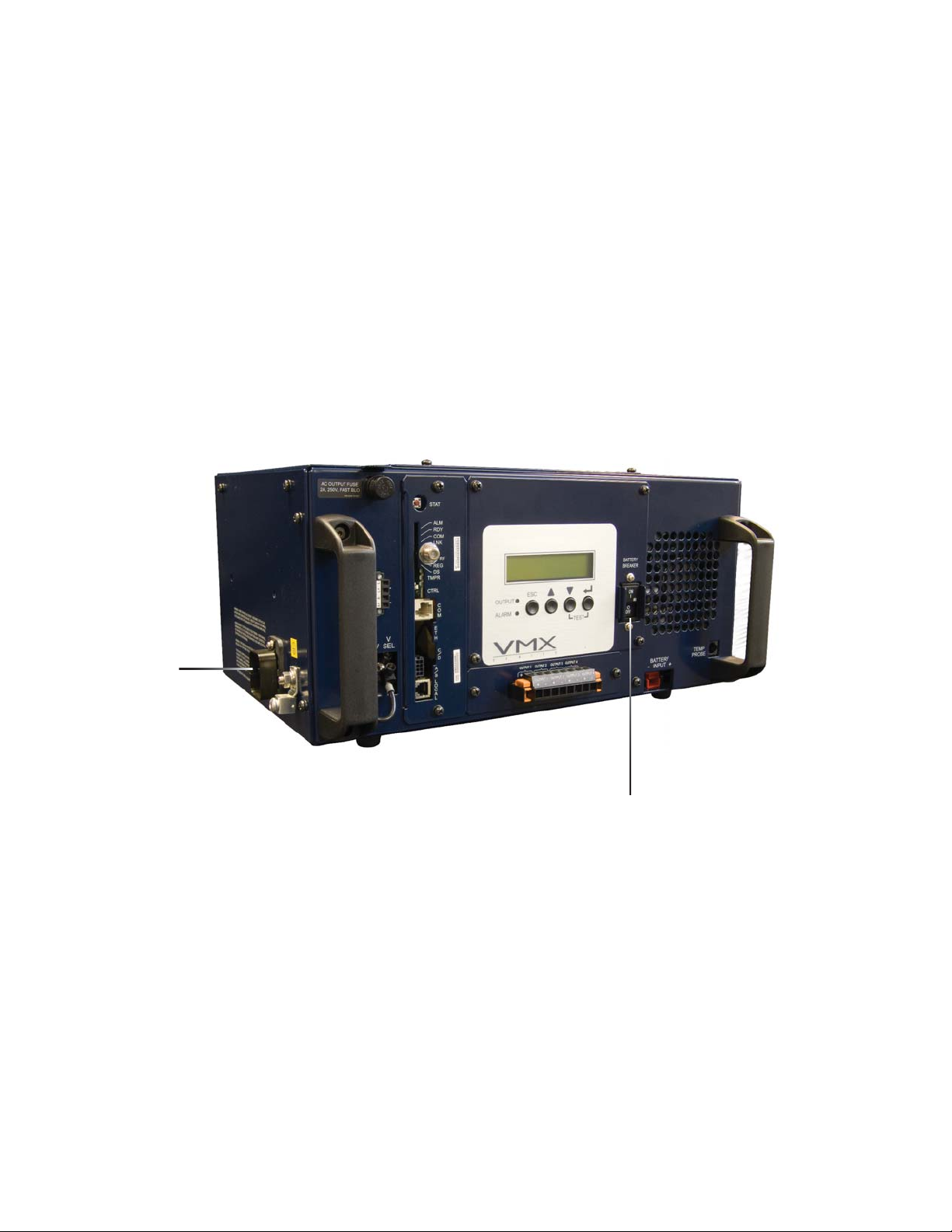
8.0 Troubleshooting, continued
8.3 Emergency Shutdown
The VMX Power Supply contains more than one live circuit. During an emergency, utility
power may be disconnected at the service entrance or main electrical panel to protect
emergency personnel. Power may still present at the output. To prevent the possibility of
injury to service or emergency personnel, always follow this procedure to safely shutdown the
power supply.
Emergency Shutdown Procedure:
STEP 1: Turn the battery breaker to OFF.
STEP 2: Unplug the AC Input Line Cord from the service entrance.
2
1
017-940-B0-001, Rev. A
57
Page 58

This page intentionally blank
Page 59

This page intentionally blank
Page 60

Alpha Technologies
Power
®
Alpha Technologies
3767 Alpha Way
Bellingham, WA 98226
USA
Tel: +1 360 647 2360
Fax: +1 360 671 4936
Web: www.alpha.com
Alpha Technologies Ltd.
4084 McConnell Court
Burnaby, BC, V5A 3N7
CANADA
Tel: +1 604 430 1476
Fax: +1 604 430 8908
Alpha Technologies
Europe Ltd.
Twyford House
Thorley
Bishop's Stortford
Hertfordshire
CM22 7PA
UNITED KINGDOM
Tel: +44 1279 501110
Fax: +44 1279 659870
Alpha Technologies GmbH
Hansastrasse 8
D-91126 Schwabach
GERMANY
Tel: +49 9122 79889 0
Fax: +49 9122 79889 21
Alphatec, Ltd
P.O. Box 56468
Limassol, Cyprus
CYPRUS
Tel: +357 25 375675
Fax: +357 25 359595
AlphaTEK ooo
Khokhlovskiy Pereulok 16
Stroenie 1, Offi ce 403
109028 Moscow
RUSSIA
Tel: +7 495 916 1854
Fax: +7 495 916 1349
Alphatec Baltics
S. Konarskio G. 48
Vilnius 2009
LITHUANIA
Tel: +370 5 213 8822
Fax: +370 5 213 7799
Alpha Technologies
9 impasse Sans Souci
92140 Clamart France
FRANCE
Tel: +33 1 41 90 07 07
Fax: +33 1 41 90 93 12
Copyright © 2007 Alpha Technologies, Inc. All rights reserved. Alpha is a registered trademark of Alpha Technologies. 017-940-B0-001, Rev. B
Due to continuing product improvements, Alpha reserves the right to change specifi cations without notice.
 Loading...